speci cation, development, and veri cation of software systems. Historically, rst ... tions, development of programs, and also maintenance of software systems.
A Method for the Development of Correct Software Peter Pepper1 and Martin Wirsing2 Contributions by: Ralph Betschko1 , Manfred Broy3, Sabine Dick1, Klaus Didrich1, Joachim Faulhaber1 , Wolfgang Grieskamp1, Heinrich Hu�mann3, Michael Mehlich2 , Wolfgang Reif 4. + Members of working group: Martin Beyer1 , Stefan Gastinger2 , Maritta Heisel1 , Friedrich von Henke5 , Liu Junbo6 , Bernd Krieg-Bruckner6 , Thomas Santen1 , Gerhard Schellhorn4 , Oscar Slotosch3 , Kurt Stenzel4 , Martin Strecker5 . Nikolas Vlachantonis7, Burkhart Wol� 6. 1
Computer Science Department, Technical University of Berlin Computer Science Institute, Ludwig-Maximilians-University of Munchen 3 Computer Science Department, Technical University of Munchen 4 Institute for Logic, Complexity and Deductive Systems, University of Karlsruhe 5 Computer Science Department, University of Ulm 6 Computer Science Department, University of Bremen 7 Computer Science Department, University of Braunschweig 2
Abstract. In requirements engineering domain modeling with formal speci cations is integrated with informal and pre-formal approaches for the construction of a formal requirements speci cation of the \functional" properties of the required system. The speci cations are used in the modeling and analysis parts of the requirement process and provide means for validation, including early prototyping and theorem-proving. An evolutionary process model is proposed for system design and program development, whereby the correctness of all development steps is checked by suitable veri cation tools. The model centers around a development graph which consists of units, e.g. formal speci cations, proofs, and programs, and relations between these units. There are three kinds of relations: syntactic relations, semantic relations, and modi cations. In each development step units are either created, transformed, or modi ed. Program and system development are understood as the development of speci cations from the requirement speci cation to a constructive speci cation which can then be directly transformed into a program. Main features of the approach are modularity, compositionality, and reusability of speci cations, programs, and proofs.
1 Introduction Traditionally, software development is a well-de ned but informal activity. Starting from an informal problem description, the construction of a software system is usually performed in several steps, in each of which a new document is produced; this document either completes, re nes, or revises a previous document, or constitutes an addition to foregoing documents. Several strategies, ranging from audits to tests (see e.g. [Som92]) are applied for validating and revising documents. A well-known drawback of these methods { and of testing in particular { is that they cannot guarantee the correctness of the system: nding errors only demonstrates incorrectness. Another drawback is the maintenance of the software systems, which is both di�cult and expensive. For example, modi cations of the source code cannot automatically be propagated to the requirement speci cation and vice versa. On the other hand, there is a rich world of research in formal methods for the speci cation, development, and veri cation of software systems. Historically, rst examples for such methods were the concepts of step-by-step re nement for the joint construction of a program and an assertion proof from its speci cation (cf. [Dij76, Hoa90, Wir83, Gri81]), and the transformational program development methods for the deduction of a program from a speci cation by transformation steps (see [DB73, BMPP88, MW79]). Both directions were more or less only addressing issues of programming in the small. For programming and development in the large there are few approaches in the area of formal methods. Only in connection with the change of data structure (see [HHJ86]) and in the eld of algebraic speci cations [GH78] have attempts been made to provide methodological support at least for speci c development steps. A second generation of formal methods aims at a more comprehensive approach to support software development across a broader spectrum of the development life cycle [BMPP88, Smi91, ORSS92]. However, even for the more sophisticated machine-supported approaches (such as Larch [GG88, Gut91], Lambda [MHF+ 92], Hol [Gor86, CGM87] and Isabelle [Pau87, NP92]) the main emphasis is not laid on development issues but on proof techniques (such as tactics) or on the integration of speci cation and programming concepts (such as the Larch Interface Languages [GH91]). Much less attention is paid to a development and life cycle model for formal software development. The Vdm method [Jon86, Jon87] provides a more comprehensive approach. Relating and integrating formal methods with more pragmatic software engineering concepts appears to be a promising way for enhancing the reliability and maintainability of software systems. Such an integration might be the most important prerequisite for scaling up formal methods and for overcoming some of the drawbacks of informal development techniques. The Vse project is a rst and very pragmatic approach in this direction. Similarly, our aim here is to integrate formal and methodological principles in order to achieve high quality and reliability in software systems. Characteristic aspects of our approach are:
{ The development principles are applicable to all phases of the software life cycle, including requirements engineering, development of design speci ca-
tions, development of programs, and also maintenance of software systems. The requirements engineering model integrates diagrammatic techniques such as E/R-diagrams and data ow diagrams with formal methods and aims at a full formal de nition of the functional requirements. The development of design speci cations and programs is fully formalized, but readability is supported by a graphical representation of developments and con gurations. { Correctness is a major issue. The notion of correctness expresses a relationship between a speci cation and its realization or, more generally, between two software documents. As a consequence, veri cation plays an important role in Korso developments. We distinguish between machine-veri ed and hand-veri ed properties. Korso aims in particular at machine veri cation. Proofs are thus an explicit part of developments and have explicit representations. { Formalization is a necessary prerequisite for a rigorous expression of the correctness requirements and as a concise basis for reasoning about software units and their development. The formal methods in Korso o�er di�erent degrees of support: formalization, validation, and veri cation. For requirements analysis it is important to give a complete formal description of the problem; in subsequent steps such a formal description may be implemented in a prototyping language and tested in order to validate it with respect to the informal requirements. The relationship between two formal descriptions, e.g. between a design speci cation and a program, can and should be veri ed using a formal proof calculus. { Scaling up formal methods to large programming systems is a central goal of Korso. In order to make this feasible, our method builds on modularity, compositionality, and reusability as key concepts. Modularization concepts are used for decomposing developments, speci cations, programs, and proofs. Compositionality ensures, in particular, that locally correct developments and proofs, which are performed for a part of a system, are also globally correct. Reusability allows the integration of previous results into new developments. This paper proposes a conceptual framework within which the aforementioned goals could be achieved. Note, however, that the issue of support tools | which are a mandatory prerequisite for the practical usability of the method | is not addressed here. The process of software development can be considered from two aspects: (A) From a methodological point of view , the process consists of di�erent kinds of activities, such as requirements analysis, formal speci cation, design of solutions, prototype validation, implementation, and so forth. (B) From a technical point of view , the process manifests itself in a collection of software documents (called \units" here. In order to constitute a \method",
the handling of these documents must not only consist of a database administration, but in addition provide speci c operations for carrying out developments. Our method addresses both issues. Viewpoint (A) will be explained in more detail in Section 2; Sections 3, 4 and 5 are devoted to the elaboration of viewpoint (B), which centers around the notion of \development graphs". Section 6 concludes with some remarks on design choices and on the practicability of the method. Example 1. We use the development of a lexical scanner as a running example in this paper. This task has been used for several studies within the framework of the Korso project (see [RSS93, AFHL92, DS93, Het94, KW94]). The so called Lex example served as a common basis for communicating various methodological viewpoints. Informally, in the Lex example a function is developed which takes a string and a sequence of regular expressions. The string is divided into substrings such that each substring matches one of the regular expressions. The main function returns the sequence of matched regular expressions and the su�x of the input string which is not matched by any of the regular expressions. The speci cation and development of this function requires in addition a number of auxiliary functions and data structures; therefore it constitutes a complete software system | albeit a very small one (which is unavoidable for a \running example").
2 A Process Model for Software Development As in most process models, we distinguish roughly several phases of software development: requirements analysis and speci cation, development of design speci cations, construction of executable speci cations, transformation into executable code, and maintenance. Each of these activities consists { as usual { of a series of steps. But in contrast to other approaches, quality ensurance activities are not separated from constructive activities and reuse is an integral part of every activity: Korso emphasizes in each step formalization, validation, veri cation, and reuse.
{ In requirements engineering diagrammatic notations such as entity-relationship diagrams and data- ow and control- ow diagrams are extended in Korso by formal descriptions in order to increase their expressiveness [Het93, Nic94]. Moreover, by translating diagrams into speci cations, we obtain a unique and coherent framework for the di�erent semiformal and formal description techniques. The resulting formal requirements speci cation serves as a \contract" for the subsequent construction of the software system. Proving properties of this speci cation helps to validate the requirements. The development of the design speci cation (that is, the high-level description of the solution) from the formal requirements speci cation consists of a
series of steps, in which more and more re ned formal descriptions re ecting the design ideas of the intended implementation are developed. Each development step in this phase refers to formal descriptions and is therefore formally veri able on the basis of the underlying semantics (see e.g. [BW95]). { The development of formal speci cations and veri cation of the correctness of developments are labor-intensive and time-consuming tasks. The reuse of formalizations, developments, and proofs can help to decrease the costs of such developments considerably (see e.g. [BP89]). Moreover, if a design speci cation is executable, it can serve as a prototype of the intended system. { Even though an executable design speci cation could already be considered as the nal program, if the underlying support system satis es the performance requirements, this will generally not be the case. Therefore, the nal software product is usually constructed by a development from the most re ned speci cation to a concrete implementation, that is, to code written in some programming language. Transformation techniques using formally veri ed transformations and reuse of software components are the main tools in this phase. { We also introduce formal methods for maintenance . With the help of formal methods it is possible to control modi cations. Moreover, it is not necessary to redo all the proofs when a speci cation or a program has been changed, since it is possible to distinguish the modi ed parts of a proof from the other parts. Non-modi ed parts can be reused; new proofs only have to be constructed for the modi ed parts in order to verify the modi cation [Rei95]. In the following we elaborate on the two major activities in the above list, viz. requirements engineering and development of design speci cations.
2.1 Requirements Analysis and Speci cation
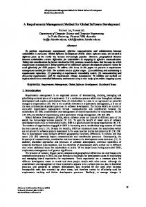
Requirements engineering in Korso means the development of a formal requirements speci cation with the help of both formal and informal methods. Apart from the use of formal methods, the development process is similar to those of classical structured approaches such as SA/SD or SSADM [AG90]. Starting from an existing system (which may or may not include computer components) one proceeds in four steps: 1. Analysis of the current status of the system. 2. Description of the essentials of the current system. 3. Modeling of the essentials of the intended system. 4. Complete description of the requirements of the intended system. The mode of proceeding in each of these steps is always a dialogue between the client and the requirements engineer. The engineer constructs and analyses a partly formal model based on the information obtained during knowledge acquisition. The model is corrected and revised in an iterative way until the objectives of the current development step have been achieved (cf. Figure 1). For a detailed description of the requirements engineering process, see [Hu�93].
Since Korso aims at correct software, the nal requirements speci cation must be formulated in a formal language so that software tools for subsequent design and development activities can be used which can trace and check the development not only on a syntactical but also on a semantical level. Our attention here is centered on functional requirements , i.e., on the exact description of the input-output behavior of the system. Although security aspects, for instance, can be handled [CHL95], non-functional requirements like hardware constraints, performance requirements, cost predictions, etc. lie beyond the scope of this paper.
Knowledge Acquisition �
GF /
Modeling
Conversion
�
O
@A
ED
Analysis
BC o
Fig. 1. Life cycle (adapted from [DHL+ 86]) In order to facilitate knowledge acquisition from experts in an application domain, the Korso method supports documents of various degrees of formality.
{ Usually, rst steps in knowledge acquisition are made in a completely infor-
mal way, leading to simple documents which do not keep to any particular speci cation language (simply natural-language text and diagrams). { During the modeling activities, the informal documents are rst re ned into semiformal diagrams and texts such as Entity/Relationship (E/R) diagrams and Data Flow Diagrams (DFDs). In this stage only limited analysis and conversion activities are possible, but the documents can be discussed with users of the intended system. { In following iterations the documents are revised, but also further formalized. For instance, E/R diagrams may be enhanced with formal data-type speci cations, or the elementary processes in a DFD may be speci ed axiomatically [Nic94]. As the formality of the documents increases, powerful software tools for the analysis of the documents become available (e.g. typecheckers, prototyping tools, theorem-provers). Parts of the modeling and conversion activities can also be computer-supported to some extent. For instance, an E/R diagram can be mechanically transformed into a formal speci cation [Het93].
Example 2. The following Figure 2 shows the end product of the requirements analysis of the informal description from Example 1. To the left of Figure 2 we see part of the development graph (see Example 3 and De nition 1 below), to the right, we have as illustration a part of the formal speci cation of the unit Scan. Scan = :::
Scan
!!
scan : seq(char) � seq(regexp) seq(regexp) � seq(char); :::
axioms 8 rest; sin : seq(char); t : regexp; rs; ts : seq(regexp) in
Match �
:::
RegExp �
'&!
LIBRARY �
%$"#
scan(sin; rs) = (t^ts; rest) , s1; s2 : seq(char): (s1 6= [] ^ s1 + +s2 = sin^ scan(s2; rs) = (ts; rest)^ (s1; t) isLongestPre xMatchOf (sin; rs)
9
);
endaxioms;
Fig. 2. Requirement speci cation for the lexical scanner
2.2 Development of Speci cations and Programs The activities that we have discussed so far lead from informal problem descriptions to a formal requirements speci cation. In the next phase, more detailed speci cations and, nally, programs are developed. We aim at the following three classes of speci cations (even though the boundaries between them are quite vague): { design speci cations of solutions (\implementation ideas"); { executable speci cations for prototyping; { programs (\e�cient implementations"). Viewed puristically, the development proceeds through all of the following stages: After the requirements analysis (as described in the previous section) we possess a document that speci es what the system has to do without giving any thought to how it may be done. Then we introduce the principal ideas for the design of the solution , but still in the very abstract form of a speci cation. Next, these ideas
are represented in a form that is executable , e.g. by a term-rewriting system. We are, however, not yet striving for e�ciency. (At this stage we are able to do early prototyping.) Finally, we seek truly e�cient solutions; that is, we generate programs . In this sense we follow the main steps of traditional software development processes. There are two main di�erences: in our approach each development step has a formal basis. When a new (version of a) speci cation or a program is constructed, it has a well-de ned formal relationship to one or more existing speci cations or programs. In general, this creates proof obligations which have to be justi ed either by hand or with the help of a theorem-prover (see Section 5). In order to reduce the development e�ort and in particular the volume of the proof, reuse of already veri ed speci cations or programs is encouraged (see Section 4). Much as in object-oriented developments, adaption of components (\development with reuse") as well as the construction of new components (\development for reuse") play prominent roles in our developments (see [GHS95]). New is the reuse of proofs in cases where errors are detected in speci cations and programs as well as in cases of modi cations in the maintenance phase. Here case studies have shown that 70 to 80% of the existing proofs can be reused, which considerably decreases the cost of proofs [Rei95]. So far we have only sketched the general framework of the overall development process. But we should also brie y point out, what kinds of activities constitute the individual steps of this process. Typical examples are:
{ Functional re nement : Given axioms are replaced by new axioms (which are
\equivalent" or \stronger"). In addition, new auxiliary functions are also frequently introduced. These new axioms and functions re ect algorithmic ideas. { Change of data structures : An \abstract" data type is realized in terms of a \more concrete" data type. A typical example is the realization of sets in terms of balanced trees or in terms of hash tables (see Section 4.4 or also [PBDD95]). { Transition to programs : The speci cation of a solution is transformed into the syntactic form of a suitable programming language. In the case of functional languages this is mostly a simple transliteration, in the case of imperative languages it requires more labor-intensive transformation or veri cation techniques. (See e.g. [BW82] or [Par90].) The availability of formal speci cations also opens new opportunities for the compilation process: certain properties { such as associativity, inverse functions, etc. { can be utilized for an extended compilation (also called \algebraic compilation"), which automatically produces highly optimized code (see [DFG+94]). The development process is nished when an executable speci cation or a program is obtained and all proof obligations are ful lled. Then the resulting program is correct w.r.t. the formal requirements speci cation.
Example 3. The overall development process for our running example of the lexical scanner is depicted by the graph in Figure 3 (cf. [BDDG93]). Single-lined arrows indicate structural dependencies (\is enrichment of"), double-lined arrows represent development relations. These relations are labeled with a symbol which indicates the kind of relation. (For details see Section 3.2.) The nal e�cient formulation of the scanning function is contained in the unit ScanGrammarRe2.
�
Scan
�
ScanGrammar +3
+3
ScanGrammarRe1
�
+3
f mm ffff mmm fffff m f f m f f mmm ffff mmm fffff
Reg2Grammar �
v
r
�
Reg2GrammarRe1
+3
�
+3
ScanGrammarRe2 Reg2GrammarRe2
hmm mm { mm { hh mmm {{{ hhhh mmm mmm {{{ h m m m h m m h m h m mmm {{ {{ mmm hhhh mmmm mmm {{ {h{hhhhh mmm m m m { { m m h h Match {{ {{ mmm mmm hhhh {{ mmm hhhhhh {{{ mmm m m { m m h {{ mmmm hhhhh {{ mmm {{ mm {{ mmmm hhh { m {{ mmm hhhh { m v
�
RegExp �
'&!
}
v
t
ETGrammar �
QQQ m mmm QQQ mmm m m mmQ Q m m m Q QQQ mm mm mm mm mmm
Grammar
w
%$"#
}
v
�
+3
ETGrammarRe
mmm mmm m m mm mmm
2:
'&! LIBRARY %$"# (
�
v
/
Fig. 3. Development Graph of Lex
3 Development Graphs On the technical level, a software development process consists of the creation of a series of documents , which may be texts, graphics, object modules, and so forth. We refer to these documents as \units". The units are related to each other in various ways, and by recording not only the units but also their relationships we obtain the concept of \development graphs". These graphs incorporate many standard ideas from traditional version-control systems in software engineering. But they extend these ideas by distinctive new concepts, re ecting Korso's emphasis on the support of formal methods: { Traditional version control uses arbitrary text-editing for creating new versions; quality assurance relies completely on a disciplined management of the development process. By contrast, our method is based on a collection of well-de ned development rules for the generation of new units.
{ Traditional version control merely indicates the existence of a \created-from"
relationship. By contrast, our method establishes formal, semantics-based relations between units, together with the pertinent proofs. { Traditional version control is mainly motivated by technical issues (such as the need for recompilation, etc.) that are needed in order to keep the \actual status" of the software system intact. By contrast, our development graphs re ect all kinds of relations between units. Hence they function as some kind of an information base for assisting documentation, redevelopment, exploratory alternative developments, and the like. An indication of this more general usage is the fact that relations may be established between various kinds of units, not only between \successive versions". In summary, we may paraphrase the principle of development graphs as \development graph = version control + formal relations" As a consequence, the various steps of the development process (as sketched in the previous section) manifest themselves as modi cations of the development graph. Moreover, it should be pointed out that a development graph does not re ect the chronological history of the development process (this history may at best be extracted on the basis of \time-stamps" on the units), rather it re ects logical relations between units.
De nition1. A development graph has units as nodes and relations between
units as edges. (These units and relations will be described in the following sections). In general, there may exist more then one relation between two units of the graph; that is, we have di�erent kinds of edges.
The example in Figure 3 illustrates a typical development graph. In the following sections we present a step-by-step explanation of the various aspects of development graphs. Diagrams in the style of Figure 3 are used for the visualization of our concepts.
3.1 Nodes Represent Units \Units" play a central role in our method. We encounter three kinds of units
which will be explained in the remainder of this section. They all share the following characteristics:
{ The idea of modularization is prevalent in all modern programming and
speci cation languages, as well as in all modern software engineering approaches. Our units apply this idea not only to language modules, but also to properties, relations, proofs, etc. { Units are the smallest entities that are subject to development steps. { Units are named and thus can be referenced.
Language Modules as Units The standard instances of units are the modu-
larization features provided by most modern languages (and known under names such as module, encapsulation, package, class, etc. In the Korso languages these are in particular: the speci cations of Spectrum, the signature, implementation, and property parts of Opal, and the templates of Troll light. Since we want to integrate the very early stages of informal requirements analysis into our framework, we include as borderline cases of \language modules" also units that are actually plain texts or diagrams, that is, semi-formal or even completely informal documents. For the HDMS-A example (which was one of the major case studies in the Korso project, see [CHL95]), the semi-formal notations of entity-relationship diagrams and data- ow diagrams have proved to be useful kinds of such units. However, for other applications other diagrammatic or schematic notations can also be interesting, for instance state transition diagrams, block structure diagrams, etc.
Property Units Property units contain additional information about language modules, that is, information which is needed in the course of the development (see Section 5.3). Due to their size and complexity it seems wise to encapsulate properties into independent units, thus integrating them naturally into the overall framework. In this way it becomes possible to develop properties further (e.g. by re-structuring them). More about property units and their relationship to language units will be said in Section 3.2. Justi cation Units Justi cations provide evidence for the claim that certain relations hold between units. If the units or the relations are informal, then the justi cations have to be informal as well. But if the units and relations involved are both formal, then the justi cation should likewise be a formal proof. Since such justi cations may be subject to further developments, they are considered as units as well. (For more details, see Section 5.) 3.2 Edges Represent Relations The units that are created in the course of a development are connected by (mostly) formal relations. From a methodological point of view, the relations between units fall into three categories: { Structural dependency relations are the usual links between language modules which occur if in some language module another one is referenced. { Property relations usually exist between a language module and its corresponding property unit. These relations normally result from proof activities that are carried out for the language module. { Development relations usually re ect the e�ects of development steps. The most important kinds of relations that we encounter here are � re nement and realization relations resulting from formal developments;
� concretization relations resulting from pre-formal developments, that is,
from transitions that add information to informal or semi-formal speci cations. As a borderline case, we subsume here the transition from an informal to a formal speci cation; � plain modi cations resulting from \arbitrary" changes. For example in Figure 3, the relations \?!" are structural dependency relations, the relations \=�)", \=�)" and \=w)" are di�erent re nement relations. (In our pictures we draw dependency relations as single-lined arrows and development relations as double-lined arrows.)
Structural Dependency Relations In order to talk about modularization concepts of languages in a general but su�ciently precise manner we introduce the following notions. De nition2. If in the description of some unit A another unit B is referenced, i.e. \textually mentioned", then we say that A refers to B or A depends on B. A con guration is a subgraph of a development graph that is closed under the refers-to relation. For instance, in a Spectrum speci cation of the kind A = fenriches B + C; : : :g, A refers to B and C. Since we require that no void dependencies occur, the speci cations B and C must exist in the development graph. (In a top-down creation of speci cations this entails the temporary need for \empty" speci cations.) In Spectrum refers-to relations are induced by unions or enrichments, in Opal or Modula-2 by imports. In most languages these dependencies are introduced under notations such as \import", \enrichment", \inheritance", etc., and mostly the refers-to relation is strictly hierarchical, but in the literature one can also nd suggestions for cyclic dependencies. As can be seen from the above de nition, the refers-to relation expresses \static" dependencies between language modules. If we therefore take one (or more) units, we have to take all units in the transitive closure over this relation in order to obtain a complete software system. A con guration then constitutes a version, that is, a \snapshot" of some intermediate stage of the software (sub)system under development. This also includes, as a borderline case, the actual stage of the development. One example for a con guration is the start con guration which is depicted on the left of Figure 2. Our discussion so far characterizes the refers-to relation only as a syntactic concept: whenever A textually mentions B we have a dependency relation of this kind. However, there are many di�erent semantical concepts that may constitute the actual meaning of the relation. In other words, our concept of refers-to dependencies actually stands for a whole class of semantical relations . Technically speaking, this means that such an edge is labeled by two attributes: the rst one characterizes the edge as being a structural refers-to relation, and the second one represents the actual semantical meaning of the relation. For these semantical meanings we have numerous possibilities that have
been thoroughly investigated in the literature on speci cation and programming languages. Typical examples are: { A is an enrichment of B; { A is a persistent enrichment of B; { B is a parameter of A. And so forth. Note that in most cases these relations may be generalised by additional signature morphisms. Example 4.
(i) In Spectrum we may establish the relation \is-enrichment-of" between
A and B, e.g. by writing A = B + f: : :g
or
A = fenriches B; : : :g:
(ii) In Opal we establish the relation \is-persistent-enrichment-of" between
A and B by writing
implementation A import B : : :
Property Relations Property units are attached to another unit of the de-
velopment graph as some kind of an attribute of that unit. Therefore, a rst attempt to represent units with attached properties and a corresponding justi cation (which contains the proof obligation \the properties are ful lled by the unit") might look as depicted on the left side of Figure 4.
A
A P
J
/
P
J
Fig. 4. Two possibilities for representing property units We chose another possibility, pictured on the right side of Figure 4. Properties are separate units in the development graph, linked to \their" unit by an edge, to which the justi cation unit is attached. In this way, we achieve greater homogeneity of the development graph for the price of introducing a new kind of edge, namely the property relation.
Property relations only serve the purpose of connecting property units to their corresponding language modules. The actual essence of this relation is captured by the justi cation unit which is attached to the edge (see Section 5). Typical examples of properties are: { Lemmas and theorems : In connection with veri cation, the property units can be used to structure proofs appropriately. That is, the user can group theorems and lemmata together according to their causal dependencies. This may also facilitate the reuse of proofs, because the structuring of the proof is governed by the user's knowledge about the application domain and not only by the technical and organizational needs of the veri cation tool. { Particular models : The understanding and analysis of a speci cation is often simpli ed, if we know about the existence of special models. Standard examples are the initial model and the terminal model. { Executability : In connection with compilation or prototyping , there are many properties that may increase the e�ciency considerably. A typical example is the view of equations as suitably directed rewrite rules. { Meta-properties : Certain properties of speci cations are referred to as \meta"properties in the literature, such as consistency (the speci cation has at least one model), sensibility (for all sorts in the speci cation there is at least one ground term which is de ned), su�cient completeness (all sorts of the speci cation have constructors, and every de ned term of a sort is provably equivalent to a constructor term of this sort).
Development Relations We view software production as a step-by-step process, where in each development step we produce new units8 ,and we do this either by { creating a new unit from scratch, or by { deriving a new unit from an existing one. De nition3. If a unit is obtained by one step of the development from some existing unit, then we say that the new unit is derived from the existing one. A collection of units which are connected by derived-from relations is called a derivation. This simply means that a derivation re ects a fragment of the development process of a software project. In simple cases, such a derivation will be a sequence, but due to our view of con gurations as graphs it is also possible that a derivation is a tree (or even a dag). Note 1. Derivations are not a recording of the history of the development process.
The derived-from relation expresses a semantical connection between two units, 8
For pragmatic reasons it is also necessary to allow the elimination of outdated units, that is, of units that are no longer referred to by other units. But for the conceptual clari cation of our model this feature need not be taken into consideration.
but it does not say anything about the time at which this relationship was established, nor the order in which the two units were created (see Section 4 below). Note 2. It may well happen that two units are related to each other both by a refers-to relation and by a derived-from relation. This situation occurs, for instance, when we derive from a given unit A a new unit B that is of the form B = fenriches A; : : : g; see above. Example 5. We turn again to the Lex example. The original requirements speci cation is based on the notion of \grammars". This notion and the accompanying functions are originally speci ed in the unit ETGrammar in a purely descriptive way by equations such as next : grammar � set(symbol) � symbol ! set(symbol) ? ? yield nonterminals of rhs of all non-terminating productions next(g; ns; t) = ns0 , 8n; n0 : symbol:([n] ! [t; n0] 2 P(g) ^ n 2 ns , n0 2 ns0);
On the way towards an implementation these grammars have to be represented by constructive data structures, that is, by structures de nable in terms of programming language constructs. The de ning equations of the functions change accordingly. This is done in the unit ETGrammarRe9: next(g; ns; t) = (�nt; ts:(selcprods(g)(nt; t) + ts)=empty)(ns);
This constitutes the development step of Figure 5. ETGrammarT
�
ETGrammarRe
+3
TTT TTT TTT TTT TT
'&!
)
LIBRARY �
%$"#
Fig. 5. Development relations between ETGrammar and ETGrammarRe On the semantical level there is an abundance of relationships that may hold between two units. In particular in the realm of algebraic speci cations these relations are extensively studied in the literature (see e.g. [EM85] and [Wir90], also for additional references). Here we focus only on the most important relations: Re nement: A speci cation Snew is a re nement of Sold (written Sold � Snew ), if the class of all models of Snew is a subset of the class of all models of Sold . This relation typically arises in the development process when axioms are added or strengthened. 9
In the example, = is the reduce operator on sets.
Equivalence: Two speci cations Sold and Snew are equivalent (written Sold � Snew ), if each is a re nement of the other (i.e. if they have the same classes
of models).
Implementation: A program p is an implementation of a speci cation S (written p !: S), if the semantics [ p] of the program is a model of S. The idea of implementation can be generalized from programs to speci cations: this is done by generalizing the notion of re nement by also admitting additional signature morphisms. In this way we can also represent the standard activities of enrichment (addition of sorts and operations) and reduction (deletion of sorts and operations). For details we refer again to the pertinent literature, e.g. [Wir90]. Note 3. It is well known from software engineering that realistic systems comprise so many modules that a \ at" representation becomes completely incomprehensible and thus unmanageable. Therefore we need additional structuring tools . A simple generalization of the development graph is the introduction of a hierarchical structure: a hierarchical development graph consists of simple units such as speci cations and programs and of units that represent whole development graphs themselves. This issue is, however, not pursued here further.
4 The Development Process In the previous section we saw how the development graph represents the history of the development (where \history" means the causal relationships, not the chronological order). That is, at any given point in time the graph re ects the status of the development carried out so far. There remains the issue of also capturing the dynamics of the development process: the activities of the users change the development graph. We refer to these activities here as \development steps". De nition4. A development step is a user activity as described in the remainder of this section. We classify development steps into three categories: { formal development steps; { pre-formal development steps; { modi cations. These categories are discussed in greater detail below. There is also a more technical distinction: Constructive steps take one or more existing units in the graph and create from them one or more new units together with appropriate relations. Retrospective steps do not create new units, rather only establish relations between existing units (which, for instance, have previously been created with a text editor).
The availability of both concepts gives the user the freedom to organize his work as it suits him best. The various development steps are realized in the form of operations, such as:
{ Add-axiom { Add-theorem { Make-refinement { Reuse-component { Restructure-configuration { . ..
We can represent these operations on the technical level by so-called graph transformations; these describe how the graph fragment under consideration
changes through the operation. Example 6. To illustrate a formal development step, we again turn to the Lex example. The transition from the descriptive speci cation ETGrammar into a constructive speci cation ETGrammarRe that was discussed in Example 5 leads to the graph transformation of Figure 6. ETGrammar
'&!
LIBRARY �
�
ETGrammar
%$"#
=)
'&!
LIBRARY �
+3
ETGrammarRe
J jjjjjjj
jj jjj jjj u
%$"#
before
after Fig. 6. Developing unit ETGrammar into unit ETGrammarRe
In this case, the development step consists of the following substeps. First, a new unit is created from scratch. Then the relation \re nement" is added to the development graph, together with a justi cation unit which contains the proof obligation and the (in this case) mathematical proof. Note 4. This paper merely describes a frame within which formal software development can take place. It is not our goal to provide a collection of concrete development strategies. (Examples for such strategies are e.g. the divide-andconquer or global-search strategies in KIDS [Smi91], the xpoint-approximation strategies in Raps [Pai83] or the data rei cation strategies in [PBDD95].) The various Korso case studies also demonstrate (implicitly) the application of various strategies (see e.g. [Het94], [BDDG93], [CHL95], [LL94]). The remainder of this section therefore only contains a representative selection of operations that are the basis of our framework (and on which strategies can be built).
4.1 Formal Development Steps The strictly formal development steps are characterized as follows: { There is a well-de ned set of operations by which the formal development steps are invoked. (This set may grow with the continued development of the system, but at any given point in time the set is xed as part of the system.) { These operations are syntactically and semantically formalized. { They usually establish well-de ned semantical relations between units. Therefore they mostly also generate proof obligations, that is, those properties that need to be proved in order to establish the validity of the relation. The following examples shall illustrate the kind of operations that are encountered here: Add-axiom
Here we obtain the situation depicted in Figure 7. A
A
�
A0 +3
=) J after
before
Fig. 7. Add-axiom The justi cation only mentions that an axiom has been added. This automatically guarantees the pertinent relation A � A0 . A stronger form of this operation, which also establishes the consistency of A0 , i.e. the property Models(A0 ) 6= ;, could be introduced. But there are better ways of achieving this e�ect (see Section 5.1). Add-theorem With this command the user has to provide the formula f, which shall become the theorem, and he has to point out the unit A, to which the theorem shall be added. The result is the following transformation of the pertinent graph fragment (see Figure 8). A /
P
A =)
before
Fig.8. Add-theorem
/
J after
P0
The property unit P of A is enriched by the claim \f is-a-theorem"; and the justi cation J contains the { still open { proof obligation for the theoremhood of f. Note that these proofs have to be carried out by subsequent { formal { development steps. Establish-consistency With this operation the user claims that a certain speci cation does have at least one model. The operation creates a property unit P which claims the consistency of A. The justi cation unit J contains the corresponding proof obligations. (See Figure 9) For example, if A is executable, then A is trivially consistent. If A has a more general axiomatization, it may be necessary to establish a mathematical model of A for proving consistency. A
A
=)
/
P
J after
before
Fig. 9. Establish-Consistency This is one of the crucial activities in the course of a development process: an \abstract" structure A shall be realized in terms of a more \concrete" structure C. This operation is discussed at length in Section 4.4. Construct-implementation This is a special case of Construct-realization. Here a speci cation A is realized in terms of a (functional) program C. That is, we achieve executability. Change-import This operation is used to re-con gure the system under consideration. It typically e�ects changes of the kind depicted in Figure 10:
Construct-realization
A
A =)
�
B �
� +3
before
B0
Fig. 10. Change-Import
�0
A0 +3
�0
J
�
B �
�
after
B0 �
+3
A unit A refers to a unit B which is in the semantical relation � to another unit B0 . Then we create a copy A0 of A which now refers to B0 instead of B. The resulting relations �0 and �0 depend on � and �. Note: In particularly simple cases { for instance, if � is \equivalence" { we may do without the copy A0 and simply relink A to B0 (so that the graph is not unnecessarily blown out of proportion). Reuse-development In the reusability approach one chooses a veri ed software component from the software database and integrates it into the actual system of units. Here it is usually necessary to adapt the component to the actual system and then to prove that the adapted component ts correctly into the system. An example is the reuse of a component consisting of an abstract speci cation S and, for example, two veri ed realizations R0 and R00 of S (see Figure 11). In order to replace an actual speci cation A in the development graph by a realization, one must adapt the abstract speci cation S to the signature of A (by a simultaneous renaming and hiding, f (S)) and then prove that the adapted abstract speci cation f (S) is a correct re nement of A. Then the adapted realization, A0 = f (R0 ) (or similarly A00 = f (R00)), is automatically a correct realization of A (cf. [GHS95]). A
A0
A +3
KS
KS
f
KS
f
S NNNNNNN
+3
NNNN NNNN NNNN NNNN N
before
"*
R0
=)
R00
f
S NNNNNNN
NNNN NNNN NNNN NNNN N
after
"*
+3
R0 R00
Fig. 11. Reuse-development If the user is not satis ed with some proof, he may come up with a better one (which may be shorter, more general, or more easily reusable). Normally, this will lead to the replacement of the old by the new proof. But we may also record the activity in the graph (see Figure 12). Here J is the old proof and J0 the new one. The relation between them is something like \equivalent", \more general" etc.
Redo-proof
We distinguish operations that occur during functional re nement (Add-axiom, , ), during change of data structures ( ),transitions to programs (Construct-implementation), and operations that may be applicable during all kinds of developments (Reuse-development, Redo-proof).
Add-theorem Establish-consistency Construct-realization
A +3
A0
A =)
J before
+3
J
A0 +3
after
J0
Fig. 12. Redo-proof
4.2 Pre-formal Development Steps
No feasible methodology for software development can be based on the assumption that one starts the development from an existing (formal) speci cation of the problem and then proceeds by (formal) transformations to the nal implementation. On the contrary, one has to accept the fact that { as already pointed out in Section 2 { a great part of the development process has to be carried out on a more or less informal level. The most important steps on this level are modi cations that can be considered as (informal) re nements. The following examples illustrate typical instances of these kinds of activities: { The user rst provides a sketch of a speci cation: fragments of the signature, explanatory texts, a couple of essential axioms (that, moreover, still disregard exceptions and the like). The initial sketch is later on re ned by completing the signature and the axiomatization. Note that this also entails the \correction" of axioms. For instance, initially one may just write the essential concept (e.g. for stacks). push (pop (s ); top (s )) = s Subsequently, one brings these axioms into the proper form s 6= empty ) push (pop (s ); top (s )) = s { Very often it will be the case that a user only provides a rough proof outline for some veri cation task. This proof outline is later turned into a complete (machine-checked) proof. Example 7. The HDMS{A case study [CHL95] demonstrates a number of such development steps, for instance: { The transition from the semi-formal notation of an entity-relationship diagram to a formal speci cation can be justi ed by reference to an automatic translation mechanism. { The elementary boxes (processes) of a data- ow diagram have been supplemented by axiomatic speci cations of their input-output behaviour. This can be seen as a generalization of the concept of adding one document to another (enrichment). Even though on these pre-formal levels there is nothing that could be formally proved, we still have the same kinds of activities as on the formal levels. The only di�erence is that the justi cation relies on informal reasoning.
4.3 Modi cation Steps
Nobody is perfect . And therefore we have to live with the fact that revisions do
occur: { It may turn out that some of the customer's requirements have changed or have been misunderstood. As a consequence, the pertinent speci cations and possibly all subsequent realizations have to be altered. { An error may have been found. For example, a given axiomatizationmay turn out to be inconsistent. (Very frequent causes for such failures are subtleties related to unde nedness.) Then the axiomatization needs to be changed. Or the fault may be as trivial as a forgotten parameter in the signature of some function. And so forth. As a consequence, the method must make provisions for plain
modi cation steps.
Nevertheless, there will usually still be a very close connection between the old and the new unit (as is clearly demonstrated by the above examples). Therefore we record such modi cations in the graph. A modi cation operation of this kind has the following e�ects: ?? ?? ?? ? �
A �
?? ?? ?? ?
=)
?? ?? ?? ?
A ? is-modi ed A0 @ ?? @@ ~ ?? @@ ~~ ~ ?? ~~ @@ ~ �
+3
�
�
before
�
~
after
Fig. 13. Modi cation
{ Since A0 is somehow derived from A, it will in most cases refer to the same units as A. { But the graph should not automatically relink all ancestors of A to A0.
This relinking is done by corresponding operations (see Section 4.1). The mechanisms there will then { in most cases { also classify the transition as a \modi cation". { The relation created simply states \is-modi ed-to". However, as an attribute we may record the detailed nature of the modi cation (change axiom, add parameter, .. .). This may be very helpful for subsequent steps, in particular when formal proofs need to be redone. A particularly important instance of this situation arises when the modi cation step is necessitated by the failure of a veri cation activity (see Section 5). In this case, the veri cation tool may record the reason for the failure, which considerably eases the repetition of the proof for the corrected speci cation.
4.4 Example: Realization of Abstract Data Structures As a slightly more complex example of a development operation, we want to brie y sketch the realization of an \abstract" data structure by a \more concrete" one. A well-known instance is the realization of sets by hash tables (cf. [PBDD95]). We assume the existence of a development graph which contains speci cations of sets and tables (that are still unrelated; see Figure 14). By invoking a special version of the operation Construct-realization, namely the operation Realize-by-Homomorphism-Explicit, these graph fragments are related as depicted in Figure 15. TABLEJJ
SET
t tt tt t t tt
JJ JJ JJ J
NAT
LIST %
y
Fig.14. Initial Situation: Sets and hash tables
SET
realized?by +3
has?prop
SET BY TABLE
Just1
Just3
Prop Just2
TABLEPP �
NAT w
nn nnn n n nn nnn
PPP PPP PPP P '
LIST
Fig.15. The nal development graph The technical details of this operation can be found in [PBDD95]. The following notes shall su�ce to give a avor of the overall procedure. { The new unit SET BY TABLE is (at least partly) automatically generated, and so is the property unit. The unit SET BY TABLE essentially copies the signature of SET and de nes the operations on the basis of tables. (That is, it enables one to view sets as abstractions of tables.) In the justi cation units the pertinent proof obligations are automatically recorded.
{ In subsequent steps the user interactively completes the fragmentary units
(by functional re nement) such that the proof obligation can nally be met.
5 Justi cations A methodology that focuses on the correctness of software evidently has to be based on the concept of veri cation. However, the inclusion of pre-formal development concepts necessitates the extension of the concept of pure veri cation to the more general notion of justi cation.
De nition5. A justi cation is a document that demonstrates the validity of a semantical relation.
The form of justi cations can be anything ranging from simple textual explanations, via reasoning by semi-formal arguments, to completely formalized, machine-checked proofs. There is a major distinction between four categories of justi cations, which is solely motivated by the di�erent degrees of reliability that can be attached to them.
Informal reasoning usually consists of purely textual arguments, explana-
tions, and illustrations. They may give a reader some con dence in the validity of the development step. Proof sketches provide a stronger form of reasoning. They incorporate the essential milestones of a proof-to-come, while not lling in all the necessary details. Rigorous proofs possess the high-quality characteristics that are traditionally required of solid mathematical proofs . (Yet, since there is no tool-support, there still remains the possibility of bugs, ranging from simple misspellings to actually erroneous conclusions.) A very common { and in practice very important { special case of rigorous proofs are references to literature , in particular to results that are found in standard textbooks.10 Formal proofs are proofs that are carried out by an automated veri cation tool, based on a well-de ned and sound formal calculus. Here, \veri cation tool" refers to the whole spectrum, ranging from humble proof checkers to very advanced (interactive) veri ers such as the KIV system [Rei95] (which is the main veri cation tool that has been used in the Korso case studies).
10
It would obviously be a waste of time to re-invent, for instance, all of graph theory in order to write some graph algorithms.
5.1 Language-level Proofs and Meta-level Proofs
Most proofs will be done on the level of speci cation or implementation languages. The classical example here is the situation where we claim that some property (expressed, for example, in the form of a Spectrum \axiom") is actually a theorem that follows from certain axioms in the speci cation. Such proofs are needed for functional re nement, change of data structures, and the construction of theorems (cf. Section 3.1). As far as tool support is concerned, automated theorem-provers can be used for speci cations and theorems in the form of Horn-formulas. A particular instance is the validation of an executable speci cation by means of term-rewriting. For proofs of syntactically more complicated formulas (such as quanti ed formulas) or induction proofs, more powerful interactive theorem provers are needed. Two other kinds of proof arise in our approach. These proofs do not directly involve the axioms and de nitions given in the speci cation and implementation texts: { Proofs of meta-properties of speci cations such as consistency, su�cient completeness, or persistent extension. These require specialized proof techniques that may involve the veri cation of formulas as well as model- and category-theoretic reasoning. For instance, proofs of consistency and persistent extension can either be trivially deduced from the syntactic form of the axioms (e.g. if these are recursive declarations or explicit de nitions) or may require the non-trivial construction of particular models. { Proofs of properties of semantical relations that are or that rely on general theorems about such relations. For instance, the transitivity and monotonicity of the re nement and the equivalence relation between Spectrum speci cations are crucial (meta-)theorems for our development method, since they ensure the global correctness of local re nements and substitutions by equivalent speci cations. Examples for consequences of these properties are the following: { Suppose that A is a persistent enrichment of B, and that B is equivalent to B0 . Then we may recon gure A (see Section 4.1) such that we obtain a unit A0 which now refers to B0 . From the de nition of equivalence and monotonicity, it follows that A0 is equivalent to A and a persistent enrichment of B0 . { Suppose that we have a sequence of re nement steps A ! A0 ! : : : ! A(n) : Suppose further that we can prove the consistency of the last version A(n) in this series. From the de nition of re nement, it can then be concluded by transitivity that all the other units A; A0; : : :; A(n?1) are also consistent. Reasoning of this kind is normally done at the meta-level in a rigorous mathematical style. In special cases, such as the one above, it is very simple and can be performed directly by the graph manager. For semi-automated reasoning in the general case, higher-order logic and dependent types appear to be suited as proof calculi.
5.2 The Role of Veri cation Conditions In many situations the hardest task is to determine which properties are necessary in order to establish the validity of a theorem. The actual veri cation of these properties is then comparatively simple { in particular, when an automated veri er is available. Therefore it is of crucial importance that all development operations in the Korso methodology explicitly state which proof obligations are required for them. Example 8. Realization by Construction (adapted from [BDDG93]): The real-
ization A0 of a unit A is constructed from scratch or by modifying the old unit. The proof obligations consist of the proof that the axioms of A are consequences of the axioms of A0 and we must also show that the de nedness conditions are preserved. Furthermore, the new unit must be consistent. The consistency proof is delayed until a constructive realization is reached in a sequence of development steps which are correct modulo consistency.
5.3 Generating and Using Properties In Section 3.1 we introduced the so-called property units . These units can be utilized at least for two purposes: { We can state here those properties that go beyond the expressive power of the speci cation language at hand. { A user can use properties in order to structure his veri cation e�orts. In the following we consider the second aspect in some more detail. The problem is that veri cation activities may make up the greater part of the time spent on a project. Therefore it can reasonably be expected that these activities are somehow re ected in the development graph. And it is certainly not su�cient that they are dumped into one huge justi cation box. On the other hand, the development method shall not be too closely coupled with speci c veri cation tools. Hence, the interiors of such tools should not be lifted to the level of the development graph. A way out of this dilemma is provided by the property units. They o�er the user a number of services: { The user can distinguish between \important" and \non-important" lemmata: lemmata of the rst kind are recorded in property units (and thus can be referenced whenever needed), whereas lemmata of the second kind are left hidden within the veri cation tool and its log les. { The user can order the (important) lemmata by distributing them over several property units which are related to each other by suitably chosen refersto relations. (Such an ordering of lemmata also organizes the corresponding proofs.) { On the basis of such a structured collection of lemmata, it will often be much simpler to identify which proofs need to be redone when a modi cation has been applied.
In this setting the sole interaction between the graph manager and the veri er consists in the communication of lemmata from property units to the veri er (either as already proven assumptions or as goals to be proved), or vice versa. Note that the methodology leaves the design of the structure completely at the user's discretion.
5.4 Proofs Modify the Development Graph Veri cation activities in uence the structure of the development process in a number of ways: { They may establish causal dependencies between certain units. (\Axioms from A are needed to prove properties in B:") { Failed veri cation attempts may lead to modi cations (when something was indeed wrong), or to additional refers-to relations (if some properties were not accessible), or to re nements (if some axioms were missing). In all these cases the veri cation e�ort causes subsequent operations on the development graph. The challenging aspect here is that { in the case of a failed veri cation attempt { the proof e�ort shall be resumed after the induced operations. Correcting speci cations or programs in a development graph, for example, establishes modi cation relations and may give rise to new semantic relationships between units and new proof obligations. All the proofs that are based on the erroneous units become obsolete. However, in order to re-establish the correctness of a modi ed semantic relation, both the generation of proof obligations and their veri cation can be based on the original proof obligations and their proofs. In such a situation, proofs as well as proof attempts can be reused to a large extent (see [RS93]). Consequently, there is a logical information ow between di�erent parts of the development graph which is caused by veri cation activities. Furthermore, veri cation generates logical information (lemmata, for example) that might be useful elsewhere in the development graph. In fact, during the veri cation of a development step, hundreds of lemmata have to be invented and proved. Some of them are worth exporting to the outside of the veri cation system. They may, for example, enrich property units of speci cations. Finally, proofs also in uence the structure of development graphs indirectly in early phases of the development.
6 Conclusion Our method for formal software development applies to all phases of the software life cycle. The approach centers around the notion of development graphs, which contain speci cations and their properties as nodes, and well-de ned syntactic and semantic relations as edges between the nodes. The method as presented here is a general framework and has to be instantiated with a particular speci cation language, a programming language, and
appropriate notions of correctness, since transformation and veri cation conditions crucially depend on the syntax and semantics of the chosen languages and have to be proven correct before they can be used for software development. We have chosen here the algebraic/axiomatic speci cation language Spectrum and the functional programming language Opal, but other choices, such as the object-oriented speci cation language Troll light or the concurrent speci cation language Sl are possible. Our method is deliberately conservative in the sense that { it is based on concepts, theories, and paradigms that are well understood and have a sound mathematical basis; { it leaves the control and design of the development process completely to the user; { it provides a collection of operations that have easily comprehensible e�ects. More ambitious and advanced ideas such as \transformational development of development and proof scripts" can be incorporated into our method and have been studied within the Korso project (see [Kri88], [HCL+ 88]); however, they have been omitted from our approach in the interest of simplicity and exibility. The method has been successfully used in a number of smaller and larger case studies (see, e.g., [BDDG93], [CHL95]). As expected, these case studies have shown that formal development and veri cation is a labor-intensive and time-consuming task. In order to make it feasible in practical applications, the following issues are of prime importance: { In order to be able to exibly control and adapt the amount of rigor during development, the formal methods have to be integrated with classical semiformal and diagrammatical approaches to software development. { Reuse of speci cations and proofs is essential for the formal development of larger applications. In many cases errors in speci cations or programs are detected during correctness proofs; after correction, reuse of those parts of the proof that are not touched by the error may substantially decrease the subsequent veri cation e�ort. { Similarly, nobody wants to develop the theory of the application domain from scratch; application-speci c data structures, algorithms, speci cations, theorems, transformations, veri cation conditions, and components have to be available in the project data base in order to make formal software development practical. { System support is indispensable for the organization of the development graph, the consistent application of formal transformations, and the proof of properties and veri cation conditions.
Acknowledgment Many colleagues from the Korso project assisted in prepar-
ing this paper with stimulating discussions, in particular the members of the System Architecture Group. Thanks to Oscar Slotosch for his critical remarks
on the draft version and to Stefan Jahnichen for his extensive comments. We are grateful to Niamh Warde and Christiane Breh-Thorweihe for their valuable help in typing and proof-reading the various drafts of this report.
References [AFHL92] Abdelwaheb Ayari, Stefan Friedrich, Ramses A. Heckler, and Jacques Loeckx. Das Fallbeispiel LEX. Working Paper WP92/39, Universitat Saarbrucken, Dezember 1992. [AG90] C. Ashworth and M. Goodland. SSADM { A Practical Approach. McGraw Hill, 1990. [BDDG93] Ralph Betschko, Sabine Dick, Klaus Didrich, and Wolfgang Grieskamp. Formal Development of an E�cient Implementation of a Lexical Scanner within the Korso methodology framework. Technical Report 93{30, TU Berlin, October 1993. [BMPP88] F.L. Bauer, B. Moller, H. Partsch, and P. Pepper. Formal Program Construction By Transformations-Computer-Aided, Intuition Guided Programming. Technische Universitat Munchen, 1988. [BP89] T.D. Biggersta� and A.J. Perlis, editors. Software Reusability, volume 1 & 2. New York: ACM Press, 1989. [BW82] F.L. Bauer and H. Wossner. Algorithmic Language and Program Development. Springer{Verlag, Berlin, 1982. [BW95] M. Broy and M. Wirsing. Correct Software: From Experiments to Applications. in this volume. [CGM87] A. Camilleri, M. Gordon, and T. Melham. Hardware Veri cation Using Higher-Order Logic. In D. Borrione, editor, From HDL Descriptions to Guaranteed Correct Circuit Designs, North-Holland, pages 43{71, 1987. [CHL95] F. Cornelius, H. Hu�mann, and M. Lowe. The Korso Case Study for Software Engineering with Formal Methods: A Medical Information System. in this volume. [CLWW94] I. Cla�en, M. Lowe, S. Wa�erroth, and J. Wortmann. Static and dynamic semantics of entity{relationship models based on algebraic methods. In B. Wol nger, editor, Innovationen bei Rechen- und Kommunikationssystemen, Informatik aktuell, pages 2{9. Springer{Verlag, 1994. [DB73] J. Darlington and R.M. Burstall. A System which automatically Improves Programs. ACTA Informatica, 6(1), 1973. [DFG+ 94] Klaus Didrich, Andreas Fett, Carola Gerke, Wolfgang Grieskamp, and Peter Pepper. OPAL: Design and Implementation of an Algebraic Programming Language. In Jurg Gutknecht, editor, Programming Languages and System Architectures, International Conference, Zurich, Switzerland, March 1994, LNCS 782, pages 228{244. Springer, 1994. [DHL+ 86] E. Dubois, J. Hagelstein, E. Lahou, F. Ponsaert, A. Rifout, E. Stephens, and F. Williams. Model Components for Requirements Engineering. Final report, ESPRIT1 METEOR project, Task1, 1986. [Dij76] E. W. Dijkstra. A Discipline of Programming. Prentice-Hall, Inc., 1976. [DS93] Axel Dold and Martin Strecker. Program development with speci cation operators { illustrated by a speci cation of the LEX scanner. Technical report, Universitat Ulm, January 1993.
[EM85]
H. Ehrig and B. Mahr. Fundamentals of Algebraic Speci cations 1: Equations and Initial Semantics, volume 6 of EATCS Monographs on Theoretical Computer Science. Springer{Verlag, Berlin, 1985. [GG88] S. J. Garland and J. V. Guttag. LP: The Larch Prover. In E. Lusk and R. Overbeek, editors, 9th International Conference on Automated Deduction (Argonne, Illinois), pages 748{750. Springer Verlag, 1988. [GH78] J. V. Guttag and J. J. Horning. The Algebraic Speci cation of Abstract Data Types. ACTA Informatica, 10(1):27{52, 1978. [GH91] J. V. Guttag and J. J. Horning. Introduction to LCL { A Larch/C Interface Language. In S. Prehn, W. J. Toetenel, G. Goos, and J. Hartmanis, editors, VDM '91 Formal Software Development Methods 4th international Symp. (Noordwijerhout, Nov. 1991) LCNS 552, pages 28{78. Springer Verlag, 1991. [GHS95] S. Gastinger, R. Hennicker, and R. Stabl. Design of modular software systems with reuse. in this volume. [Gor86] M. Gordon. Why Higher-Order Logic is a good Formalism for Specifying and Verifying Hardware. In G. J. Milne and P. A. Subrahmanyam, editors, Formal Aspects of VLSI Design (Edinburgh Jan. 1985), pages 153{179. North-Holland, 1986. [Gri81] D. Gries. The Science of Programming. Springer Verlag, 1981. [Gut91] J. V. Guttag. The Larch Approach to Speci cation. In S. Prehn, W. J. Toetenel, G. Goos, and J. Hartmanis, editors, VDM '91 Formal Software Development Methods 4th Intern. Sympos. (Noordwijkerhout, Oct. 1991) LNCS 551. Springer Verlag, 1991. [HCL+ 88] F.W. von Henke, J.S. Crow, R. Lee, J.M. Rushby, and R.A. Whitehurst. The EHDM veri cation environment: an overview. In 11th National Computer Security Conference, Baltimore, NBS/NCSC, 1988. [Het93] R. Hettler. Zur U bersetzung von E/R-Schemata nach SPECTRUM. Technischer Bericht TUM-I9333, TU Munchen, 1993. [Het94] R. Hettler. A Requirement Speci cation for a Lexical Analyzer. Technical Report TUM-I9409, TU Munchen, 1994. [HHJ86] J. He, C. A. R. Hoare, and J.W.Sanders. Data Re nement re ned. In G Goos and J. Hartmanis, editors, European Symposium on Programming, LNCS 213, pages 187{196. ESOP 86, 1986. [Hoa90] C. A. R. Hoare. Developments in Concurrency and Communication. Addison-Wesley Publishing Company, 1990. [Hu�93] H. Hu�mann. Zur formalen Beschreibung der funktionalen Anforderungen an ein Informationssystem. Technical Report TUMI-9332, Technische Universitat Munchen, 1993. [Hu�94] H. Hu�mann. Formal foundations for pragmatic software engineering methods. In B. Wol nger, editor, Innovationen bei Rechen- und Kommunikationssystemen, Informatik aktuell, pages 27{34. Springer{Verlag, 1994. [Jon86] C. B. Jones. Systematic Software Development Using VDM. Prentice-Hall, 1986. [Jon87] K. D. Jones. Support Environments for VDM. In D. Bjorner, C. B. Jones, M. Mac An Airchinnigh, and E. J. Neuhold, editors, VDM '87 { VDM - A Formal Method at Work (Bruessel March 1987), pages 110{118. Springer Verlag, 1987.
[Kri88]
B. Krieg-Bruckner. Algebraic formalisation of program development by transformation. In H. Ganzinger, editor, European Symposium on Programming 1988, LNCS 300, pages 34{48. Springer, 1988. [KW94] L. J. Kolyang and B. Wol�. Transformational Development of the LEX Example. In B. Krieg-Bruckner, editor, Programmentwicklung durch Spezi kation und Transformation | Bremer Beitrage zum Verbundprojekt Korso, volume 2 of Informatik Bericht. Universit at Bremen, 1994. [LL94] C. Lewerentz and T. Lindner. Case Study Production Cell: A Comparative Study in Formal Speci cation and Veri cation. FZI Publication, FZI Karlsruhe, January 1994. [MHF+ 92] E. Mayger, B. Harris, S. Fin, M. Fourman, and M. Francis. Version 4.2 LAMBDA documentation. Technical report, Abstract Hardware Limited, 1992. [MW79] Z. Manna and R. Waldinger. The Logic of Computer Programming. IEEE Transactions on Computers, 27(3):199{229, 1979. [Nic94] F. Nickl. Ablaufspezi kation durch Daten u�diagramme und Axiome. In B. Wol nger, editor, Innovationen bei Rechen- und Kommunikationssystemen, Informatik aktuell, pages 10{18. Springer{Verlag, 1994. [NP92] Tobias Nipkow and Lawrence C. Paulson. Isabelle-91. In Deepak Kapur, editor, Proc. 11th Int. Conf. Automated Deduction, pages 673{676. LNCS 607, 1992. [ORSS92] E. R. Olderog, S. Rossig, V. Sander, and M. Schenke. ProCoS at Oldenburg: The Interface between Speci cation Language and occam-like Programming Language. Technical Report 3/92, Universitat Oldenburg, 1992. [Pai83] R. Paige. Transformational programming { applications to algorithms and systems. In 10th ACM POPL Symposium, Austin, Texas, 1983. [Par90] H. Partsch. Speci cation and Transformation of Programs - A Formal Approach to Software Development. Springer{Verlag, Berlin, 1990. [Pau87] L. C. Paulson. Logic and Computation: Interactive Proof with Cambridge LCF. Computing Reviews, 1987. [PBDD95] P. Pepper, R. Betschko, S. Dick, and K. Didrich. Realizing Sets by Hash Tables. in this volume. [Rei95] W. Reif. The KIV-Approach to Software Veri cation. in this volume. [RS93] W. Reif and K. Stenzel. Reuse of Proofs in Software Veri cation. In Shyamasundar, editor, Conference on Foundations of Software Technology and Theoretical Computer Science, LNCS 761, Bombay, India, 1993. Springer. [RSS93] Wolfgang Reif, Gerhard Schellhorn, and Kurt Stenzel. Developing a veri ed lexical scanner { a methodological case-study with the KIV System. Technical report, Universitat Karlsruhe, 1993. [Smi91] D. R. Smith. KIDS A Knowledge-Based Software Development System. In M. R. Lowry and R. D. McCartney, editors, Automating Software Design, pages 483{514, 1991. [Som92] I. Sommerville. Software Engineering. Addison{Wesley, Mass., 3rd edition, 1992. [Wir83] N. Wirth. Algorithmen und Datenstrukturen. Teubner, 1983. [Wir90] Martin Wirsing. Algebraic Speci cation. In J. van Leeuven, editor, Handbook of Theoretical Computer Science, Amsterdam, 1990. North-Holland. This article was processed using the LATEX macro package with LLNCS style