COMPUTER-AIDED DESIGN Computer-Aided Design 33 (2001) 545±559
www.elsevier.com/locate/cad
A foundation for interoperability in next-generation product development systems q Simon Szykman a,*, Steven J. Fenves a,1, Walid Keirouz b, Steven B. Shooter c a
b
National Institute of Standards and Technology, 100 Bureau Drive, Stop 8263, Gaithersburg, MD 20899-8263, USA Department of Computer Science, Byblos Campus, Lebanese American University, 475 Riverside Drive, #1845, New York, NY 10115, USA c Department of Mechanical Engineering, Bucknell University, Lewisburg, PA 17837, USA Received 25 October 1999; revised 6 October 2000; accepted 4 December 2000
Abstract United States industry spends billions of dollars as a result of poor interoperability between computer-aided engineering software tools. While ongoing standards development efforts are attempting to address this problem in today's tools, the more signi®cant demand in nextgeneration tools will be for representations that allow information used or generated during various product development activities to feed forward and backward into others by way of direct electronic interchange. Although the next generation of tools has the potential for greatly increased bene®ts, there is also a potential for the cost of poor interoperability to multiply. The goal of this work is to develop representations of information that are unavailable in traditional computer-aided engineering tools to support the exchange of product information in a distributed product development environment. This paper develops a vision of next-generation product development systems and provides a core representation for product development information on which future systems can be built. Published by Elsevier Science Ltd. Keywords: Design modeling; Interoperability; Knowledge representation; Product models; Product data exchange
1. Introduction Since its advent, computer-aided design and manufacturing (CAD/CAM) has had an immeasurable impact on product development in engineering industry, and consequently on society as well. As a result of their signi®cance, CAD/CAM technologies were identi®ed by the National Academy of Engineering in 1989 (the NAE's 25th anniversary) as an outstanding engineering achievement over the preceding 25 years, and more recently by the American Society of Mechanical Engineers as one of the greatest technologies of the 20th century [1]. As these technologies mature further, there is little doubt that their impact on product development will continue. In the past, product development was often done within a single company by co-located design teams. In more recent years, there has been a shift in product development paradigms. Product development is being done more often q This work was performed while Professors Keirouz and Shooter were guest researchers at the National Institute of Standards and Technology. * Corresponding author. Tel.: 11-301-975-4466; fax: 11-301-975-4482. E-mail address:
[email protected] (S. Szykman). 1 Senior Research Associate, University Professor Emeritus of Civil and Environmental Engineering, Carnegie Mellon University.
0010-4485/01/$ - see front matter Published by Elsevier Science Ltd. PII: S 0010-448 5(01)00053-7
by geographically and temporally distributed design teams. There is a high level of outsourcing, not only of manufacturing but also of actual product development efforts. Product development across companies, and even within a single company, is often done within a heterogeneous software tool environment. The Internet and intranets are supplanting paper and telephones as a means of exchanging product development information. As a result of this new product development paradigm, there is a greater need for software tools to effectively support the formal representation, capture and exchange of product development information. The existing generation of computer-aided engineering (CAE) software tools has undeniably revolutionized product development in contrast to methods used before the advent of these technologies. Nevertheless, the current generation of product development software tools addresses the needs of traditional product development processes, and does not adequately support the needs of industry's new paradigm described above. People are exchanging information across distributed design teams and corporate boundaries earlier, and reusing information to a greater extent. But because existing software tools do not capture a broad spectrum of product development information, these exchanges occur
546
S. Szykman et al. / Computer-Aided Design 33 (2001) 545±559
informally (face-to-face across a table, by phone, by paper). It is a lack of formal representations for product development information that creates a signi®cant barrier to its effective capture and exchange. In other words, engineers are getting by not with the support of existing software tools but despite the lack of support from them. The current generation of software tools is not designed to support at a formal level the kinds of interactions that occur, to the extent that engineers would prefer. These views are not held exclusively by the authors, but are representative of industry input obtained at several workshops held at the National Institute of Standards and Technology (NIST) in recent years: the NIST Design Repository Workshop [2]; Tools and Technologies for Distributed and Collaborative Design Workshop; and the NIST/ATP Workshop on Intelligent and Distributed CAD [3]. The CAD/CAM/CAE software industry is ultimately a customer-driven one. It is, therefore, expected that as needs (such as those identi®ed previously) mount, a new generation of tools will emerge to address these needs. The question that remains unanswered is: at what cost? Despite the acknowledged bene®ts of today's tools, their widespread use has in many cases come at great expense to industry as a whole because of a lack of interoperability between tools. While these expenses do not approach the level of savings resulting from the use of CAE technologies, they do offset the overall bene®ts. These expenses are inevitably passed on to industry customers, and ultimately to consumers. A study performed by the NIST Strategic Planning and Economic Assessment Of®ce conservatively estimates the economic cost due to lack of interoperability in the United States automotive supply chain alone at one billion dollars per year [4]. The study also estimates costs in the US aerospace, shipbuilding, and construction machinery industries at about 400 million dollars per year (for each of those sectors), assuming the interoperability costs are proportional to those in the automobile industry. As the complexity of products increases and product development becomes more distributed, new software tools will begin to cover a broader spectrum of product development activities than do the traditional mechanical CAD systems. Accordingly, the ability to capture, in an effective and formal manner, additional types of information will become a critical issue. This paper develops a vision of next-generation product development systems and provides a core representation for product development information on which future systems can be built. This paper does not put forth speci®c technologies that will be incorporated into next-generation tools, but rather seeks to address potential interoperability problems proactively, rather than reactively, by providing this core as a foundation for improved interoperability among software tools in the future. The costs of poor interoperability among today's tools are likely to be compounded signi®cantly in the future if the problem remains unaddressed. The work presented in this paper
addresses a fundamental problem whose solution can impact literally billions of dollars of costs to industry. The economic bene®ts notwithstanding, the effort of developing a generic knowledge infrastructure for the next generation of tools is one that neither industry nor the CAD/CAM/CAE vendor community is likely to undertake alone. Historically, software tool vendors have considered proprietary data representationsÐa signi®cant source of interoperability problemsÐas part of their competitive advantage. Working to eliminate the barriers to interoperability is often viewed by a software vendor as something that will make it easier for customers to purchase and use a competitor's product rather than those sold by that company. This perceived threat to a competitive advantage provides a disincentive for vendors to address interoperability problems. Indeed, this is one of the main reasons that efforts to integrate data exchange standards such as ISO 10303, informally known as STEP (Standard for the Exchange of Product Model Data) [5] into the existing generation of software tools has met with resistance from vendors despite requests from, and clear bene®ts to, their industry customers [2]. While engineering companies in industry stand to bene®t from work along these lines, they too are unlikely to undertake such an effort. This is a result of industry research and development trends that have shifted from basic research and development (R&D) to project-oriented R&D. This change makes it dif®cult for a company to use project-speci®c budgets to fund work that is acknowledged as bene®cial, but has diffused impact. What limited funds are available for generic R&D are generally applied to problems where bene®ts can readily be mapped either to a set of related projects, or to the corporate bottom line, in a short time frame. These cultural issues have served as obstacles to the development of technical solutions to interoperability problems in existing tools, and run the risk of similarly affecting the next generation of software systems. The National Institute of Standards and Technology has US industry as its primary customer and works to address problems that have signi®cance to industry, but that companies are not likely to solve on their own for one reason or another. NIST's emphasis is on economic impact to industry and society on a broad level rather than a corporate bottom line. Furthermore, NIST is not biased toward a particular class of problems, company, or industry sector, focusing instead on generic solutions that have broad-based applicability in industry. As a result, NIST is uniquely situated to invest in an effort to anticipate and address interoperability needs in next-generation product development systems. This paper is organized as follows: Section 2 describes related work done in the area of representation and modeling of design knowledge, Section 3 discusses interoperability issues in the context of product development, Section 4 presents a vision for next-generation product development systems, Section 5 presents a representation for product development information that addresses the
S. Szykman et al. / Computer-Aided Design 33 (2001) 545±559
needs motivated in earlier sections, and Section 6 provides a discussion of areas for future research. 2. Related research Traditional CAD systems are limited to representation of geometric data and other types of information relating to geometry such as constraints, parametric information, features, and so on. The engineering design community has been developing new classes of tools to support knowledge-based design, product data management (PDM), and concurrent engineering. When contrasted with traditional CAD tools, these new systems are making progress toward the next generation of engineering design support tools. However, these systems have been focusing mainly on database-related issues and do not place a primary emphasis on information models for artifact representation [6±10]. Furthermore, although these systems can represent some kinds of non-geometric knowledge (e.g. information about the design process, manufacturing process, bills of materials, etc.), representation of the design artifact itself is still generally limited to geometry. This impacts the utility of a range of software tools used in engineering industry. As an example, the lack of a formal product representation that includes function, behavior and structure has been identi®ed as a shortcoming of existing PDM systems [11]. Because of industry's increasing dependence on product information beyond simply geometric data, this work focuses on the development of an artifact representation that encompasses broader engineering design content. This content includes representation not only of geometry, but also of function, behavior, physical and functional decompositions, mappings between physical structures and function, and various kinds of relationships among these entities. The product information representation presented in this paper follows a signi®cant body of earlier work in the area of artifact representation. The high-level division of artifact information into the categories of form, function and behavior has its roots in earlier work in intelligent design system development. Examples of such work in the arti®cial intelligence community include the qualitative simulation work by de Kleer and Brown [12], behavioral and functional representation by Iwasaki and Chandrasekaran [13], functional representation by Chandrasekaran et al. [14] and successive representations from projects such as KRITIK [15], INTERACTIVE KRITIK [16], the YMIR project [17], and others. Work done in the design and engineering community includes CONGEN [18], the MOSES project [19], the GNOSIS IMS (Intelligent Manufacturing System) project [20], Function±Behavior±State Modeler [21], and a Function±Behavior±Structure framework [22]. Although the representation presented in this paper has some characteristics in common with earlier research, such as a basic division of artifact information into form, function and behavior, this work is most directly descended from the
547
representation developed as part of the NIST Design Repository project [23]. That work is based in part on the CONGEN architecture [18], which made use of the SHARED object model [24] as a representational foundation. As will be described in Section 5, the work presented in this paper has drawn not only on the NIST Design Repository project, but also several other ongoing efforts at NIST. 3. Interoperability and product development As cited previously, US industry spends billions of dollars as a result of poor interoperability between computer-aided engineering software tools. Ongoing standards development efforts in various industries are attempting to address this problem. Among the success stories in standards development is STEP (Standard for the Exchange of Product Model Data). While individual companies hesitate to provide actual costs associated with speci®c processes or activities, they have been willing to provide a few data points regarding the use of STEP. The Lockheed Martin F-22 program shows consistent savings using STEP, including a 50% process saving for composites and projected savings of 27% on tool design for CAD/CAM systems. The Boeing 767 and 777 programs reported a 75% time savings in processing designs from engine suppliers using STEP, and the Boeing C-17 program reduced time to transfer bill of materials data from weeks to minutes using STEP, with an average of 8000 part data exchanges per night [25]. While these data indicate the utility of data exchange standards to improve interoperability, viewing these as cost savings is the result of a perspective skewed by the context of poor interoperability. This level of savings can only be achieved because the costs incurred due to interoperability problems are very high. In other words, the remedy to the problem is of great importance only because the problem itself is so signi®cant. Faced with these problems today, a retrospective viewpoint leads to the observation that if interoperability issues had been successfully addressed earlier on, industry might have avoided some of these wasted costs entirely, instead of working to reduce waste after the fact. It is this observation, along with a projection of how product development in industry is changing, that motivates the need to address these issues in next-generation product development software systems. While existing standards efforts focus on enabling interoperability among tools that address a given product development activity (such as geometric CAD), the more signi®cant demand in next-generation tools will be for representations that allow information used or generated in various product development activities to feed forward and backward into others by way of direct electronic interchange. The objectives of the present work are to develop representations of information that are unavailable in traditional CAD/CAM/CAE tools to support exchange of knowledge in the new product development paradigm, and to help
548
S. Szykman et al. / Computer-Aided Design 33 (2001) 545±559
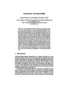
Fig. 1. Monolithic product development system.
avoid a proliferation of proprietary formats in next-generation commercial software tools. This work is not itself a standards development effort. Rather, it is an attempt to identify needs and provide a generic information representation core that can serve as a foundation for development of new systems, and, at some point, for future standards development efforts. We do not propose technologies that affect implementation-level development of software tools, but provide an infrastructure that will facilitate the capture and exchange of information among commercial tools that use it as a starting point and build upon it. 4. Next-generation product development systems The basic assumption underlying this work is that the change in product development paradigm identi®ed in the Introduction will lead to a new generation of software tools. This next generation of tools will be driven by an increased industry focus on representation, capture, and exchange of product information and product development knowledge. Existing computer-aided engineering tools are focused primarily around geometric CAD and analysis, with some tools supporting CAM activities such as process planning. Next-generation systems will enable the capture of a broader variety of product information, and will support a wider range of product development activities than do existing tools. The vision held by some for future product development tools is that of a monolithic software system. In this vision, the product development process will be supported by a single integrated application suite. Such a tool would attempt to address the needs of the new product development paradigm, allowing teams that are potentially distributed geographically or across corporate boundaries to access tools and data at different phases of product development in order to produce a product (see Fig. 1).
This vision, though not an uncommon one, has a number of drawbacks associated with it. In general, since a monolithic system is intended to be as complete a solution as possible, less emphasis is put on interoperability with other systems. Because interoperability becomes a problem, collaboration with users of other tools becomes dif®cult. What has happened in some cases among the existing generation of tools is that a large company will make a statement to the effect of: `If you want to do business as part of our supply chain, you will use this particular software tool.' Since monolithic systems tend to be expensive, among those priced out of the running are many small and medium sized businesses that form a large segment of the industry community. These limitations sti¯e competition, resulting in prices to the customers and end users that are higher than they might otherwise have been. Such systems also tend to tie users to one vendor, making the migration to a new tool suite problematic should a better system come along at some later point in time. Lastly, a monolithic tool suite will often result in a sub-optimal set of technologies. It is unlikely that a system that provides technologies for a variety of activities will be the best at what it does in all cases, particularly when a tool that might be the best solution for one company may not be for another. Some software vendors, rather than working to build a monolithic system, are working with a business model under which they establish relationships with other software companies and work to design interfaces between tools to make integration more seamless. This philosophy has the potential to offer greater customization of software tool suites. The drawback, as a practical matter, is that choice is likely to remain limited, this time to a set of companies who have established these strategic partnerships. In our view, the ideal next-generation systems for product development will be those with which individual companies, or teams involved in given product development
S. Szykman et al. / Computer-Aided Design 33 (2001) 545±559
549
Fig. 2. Product development using a heterogeneous suite of software tools.
activities, can collaborate using a heterogeneous set of software tools, and still exchange information meaningfully and pass knowledge between various phases in the process. Assuming the interoperability barrier can be overcome, this vision avoids several of the disadvantages associated with a monolithic system. Companies would not be required to standardize on the same software platform in order to collaborate on product development. Smaller companies using individual software tools due to limited resources would still be able to compete to be part of a larger company's supply chain. Larger companies would be able to assemble what they consider to be the best suite of tools from a selection of existing software products (possibly from competing vendors), and would be able to migrate more easily to new tools, although some effort would still be involved in doing so. We de®ne the Engineering Context as the entire body of information and engineering knowledge that evolves throughout the product development process. Under the vision of a customizable and ¯exible product development tool suite, multiple software toolsÐpotentially from competing vendorsÐare used during different product development activities at various stages of the design process, creating, adding to, and modifying the engineering context. Information generated by some tools during some activities will be used by other tools at other stages of the design process. In order to achieve the interoperability required by this vision, a tool that requires information created by a different tool must be able to receive that information irrespective of which tool created it. This, in turn, requires that the formal representation of product information (or at least that portion of the engineering context that is to be shared with other applications) be available in a standardized form. It is important to note that tools need not be able to read native data ®les created by other systems; what is required is only that a tool be able to serve
information in a format that other tools can interpret. Thus, although vendors would need to agree to use this standardized format for exchange of engineering information, they would not be required to standardize on native or application-internal data formats. The vision of a ¯exible product development tool suite is shown in Fig. 2. In some cases, tools from a single vendor may be designed to share a common database as is illustrated with the users in the top half of the ®gure. In other cases a single tool may have an individual database as shown in the bottom left portion of the ®gure. The ` £ 's in the ®gure denote the data exchange interfaces required to exchange or externally store product information in a standardized format. Although it is not necessary for vendors to adopt the standardized representation as their native representation, those that do would not require a translational step to exchange or store data externally. The software tool in the bottom left portion of the ®gure does not show a data exchange interface for this reason. The large database at the bottom of Fig. 2 represents the engineering context (the cloud represents the fact that the characterization of the engineering context as a single database is meant ®guratively and may not be indicative of its true instantiation). Whether the actual instantiation of the engineering context takes the form of a centralized database, a distributed database, a collection of individual ®les created by separate applications, etc., is an implementation-level issue. The focus of this work is not on implementation, but on providing a generic core for representing the engineering context as a basic foundation for interoperability. Regardless of the form that the engineering context embodies, for a tool to be able to retrieve and interpret information generated by other tools in a heterogeneous software environment, interoperability issues must ®rst be addressed at the information representation and exchange level.
550
S. Szykman et al. / Computer-Aided Design 33 (2001) 545±559
5. Representing the engineering context 5.1. Technical approach The preceding discussion presents a vision that motivates the development of a foundation for representation of design information that is non-proprietary and not tied to a single vendor. From the interoperability perspective, in an ideal world all vendors would use the same representation making interoperability problems irrelevant. Realistically, it is not likely that all CAD/CAM/CAE vendors will agree on a common product information representation, or even that they will want seamless exchange with competing systems. Nevertheless, work toward this goal is still very valuable for several reasons. First, agreement on requirements and implementations to any extent is better than none. To whatever degree a speci®cation is adopted in multiple implementations, exchange of information will be that much less problematic even if a total exchange is not seamless. Addressing the problem in anticipation of next-generation systems, rather than in response to failings among those systems after they have been developed, increases the likelihood that common solutions will be adopted. Second, assuming realistically that some interoperability problems will exist in the future, it is also probable that some sort of standards development efforts will ensue in response. The work being done here can provide a starting point for those future standards. For both of these reasons, simplicity is a key requirement for the representation being developed. Simplicity also makes a proposed representation more appealing to users. This is a critical issue since vendors must believe that a broad market will exist before they would consider using such a representation. Because of a need for broad appeal among potential customers, a product information representation should be domain-independent and should not be tied to any one product development process. To address this last point, an effort in modeling design information ¯ow was undertaken. This effort examined several product development processes and proceeded to develop a generic model of the ¯ow of product information independent of any one design process model. This project identi®ed common classes of information used by designers, activities that were common to various design processes (even though the sequences of those activities were often not common to different processes), as well as the kinds of abstractions and transformations of information that occurred in the product development process. The results of that effort, described further in Ref. [26], provided significant input into developing the actual content requirements for the information representation presented in this paper. Based on these issues, in order to enable the vision of next-generation product development discussed earlier, the goal that was set for this effort was to develop formal representation that could form the core of the engineering context discussed above. This core is intended to be an abstraction
of concepts that are common across many design activities. The broader engineering context would include this common core along with additional concepts (objects, relationships, attributes, etc.) such as activity- and domainspeci®c extensions and specializations that may not be common to many activities. The core would provide interoperability across activities, while extensions to the core might or might not require additional translators or interpreters depending on the extent of adoption among different software tools. The requirements for the core were to develop a knowledge representation that is: ² ² ² ²
not tied to a single vendor software solution; open and non-proprietary; simple and generic; extensible by allowing augmentation of the core with additional concepts to create a broader engineering context; ² not dependent on any one product development process; and ² capable of capturing that portion of the engineering context that is most commonly shared in product development activities. The representation was also intended to provide interoperability among four in-house research and development projects. 1. The NIST Design Repository project, developing a distributed framework to support the creation of design repositories, the next generation of design databases [23]. 2. The Design-Process Planning Integration project, developing interface speci®cations and prototypes to enable manufacturability analysis during conceptual product design [27]. 3. The Design for Tolerancing of Electro-Mechanical Assemblies project, working to advance the use of tolerancing at early stages of design and to investigate the best use of available methods of tolerance analysis and synthesis [28]. 4. The Object-Oriented Distributed Design Environment project, developing a software prototype of such a system. Each project team had been proceeding to develop its own product model, with little or no interaction among the projects. A comparison of the product models developed or proposed by the four projects showed that of the 133 terms (object and attribute names) used in the models, 99 terms (74%) appeared in one model only and only three terms (2%) appeared in all four models. This comparison excludes terms that are speci®c to the domain of one project only, such as process- and tolerance-related terms. It therefore appeared that there was not much commonality. The next step was the development of a core combined product model that could be shared across projects and
S. Szykman et al. / Computer-Aided Design 33 (2001) 545±559
551
Fig. 4. Relationship class hierarchy. Fig. 3. Object class hierarchy.
extended as needed to suit the concerns of the individual projects. Although the core model most closely resembles the model originating from the NIST Design Repository project, terms from the other three projects were also incorporated, showing the synergy provided by broader exposure and discussion. The examination of multiple independentlydeveloped models, abstracting out the commonalities, and distilling their basic information content, led to a more generic and extensible representation than any one of them had previously provided. The representation that emerged is proposed as an information transfer mechanism for next-generation product development tools, either in the basic form presented in this paper or as the `foundation' or base-level representation of the multilevel design information ¯ow model presented in Ref. [26]. 5.2. The core representation The core representation consists of classes of objects and relationships. The full listing of all classes in the core representation is shown in Appendix A. In the text that follows, names are classes are capitalized and names of attributes are not. The syntax and common characteristics of the classes are discussed ®rst, followed by their semantics. The object class hierarchy is shown in Fig. 3. 2 Syntactically, all object classes are specializations of the abstract class DRP_Object, which has attributes name, information, and sources and destinations of references and relationships (discussed below). The abstract class Restricted_DRP_Object specializes the DRP_Object class and has additional attributes constrained_by and required_by serving as links to Constraints and Requirements, respectively. The specializations of the DRP_Object class are the Artifact, Behavior and Speci®cation classes; specializations of the abstract class Restricted_DRP_Object are the Function, Flow, Form, Geometry and Material classes. The Function class further specializes into the Transfer_Function class. The attributes of the object classes are discussed below in the context of their semantics. The relationship class hierarchy is shown in Fig. 4. Simi2 Abstract classes in the ®gure are denoted by `(a)'. An abstract class is a class for which instances cannot be created, but which exists for the convenience of grouping attributes that are common to all of its subclasses so that these attributes can be inherited by the subclasses.
larly to objects, all relationships are specializations of the abstract class DRP_Relationship, with attributes name and information. The specializations are the Requirement, Reference, Constraint, and Set_Relationship classes, the latter further specializing into Directed_Set_Relationship and Undirected_Set_Relationship classes. In order to make the representation as robust as possible without having to prede®ne all possible attributes that might be relevant in a given set of domains, the core representation is limited to those attributes required to capture generic types of product information and to create links and associations among the entities shown in Figs. 3 and 4. The representation intentionally excludes attributes that are domain-speci®c or entity type-speci®c. Such attributes can be represented, but are not explicitly built into the schema. Instead, each object and relationship has an Information entity associated with it. The class Information is a container for all detailed information, consisting of a brief textual description, a textual documentation string (which typically provides a ®le path or URL referencing more substantial documentation than is given by the brief description), a methods slot for the methods operating on the object, and a properties slot that contains a set of attribute±value pairs stored as strings. Domain- or entity typespeci®c attributes are represented using the properties attribute. This lack of specialization of entities results in a small number of entity de®nitions that are broadly applicable. As will be illustrated in an example below, this allows the representation to be used to represent a 9-Volt electric motor and a 9-Volt electrical current ¯ow without prede®ning a domain-speci®c attribute called voltage in either of the entity de®nitions. All specializations of the abstract class DRP_Object except Flow have their own decomposition hierarchies, represented by attributes such as subartifacts/subartifact_of for the Artifact class. In addition, most of the objects and relationships also have an attribute called type, a symbolic classi®er. All of the entity classes that have a type also have an individual hierarchical taxonomy of terms associated with them. These terms are generic enough to designate a broad variety of engineering artifacts, and yet concise enough to provide a manageable standardized vocabulary. The type classi®er is a string corresponding to one of the terms within a given taxonomy. For example, the engineering function `Convert' is one of numerous subtypes of `Transform_function,' which is in turn one of several subtypes of `Function.' Another way to view this is that
552
S. Szykman et al. / Computer-Aided Design 33 (2001) 545±559
several of the entities in the representation have their own individual generic engineering classi®cation hierarchies that are unrelated to the entity class hierarchies shown in Figs. 3 and 4. The motivation for providing typing information and associated taxonomies on which to draw for artifact modeling is twofold. The standardized vocabulary facilitates indexing and retrieval of product knowledge for design reuse. The classi®cation of an entity (e.g. an Artifact or Function or Flow) within its associated taxonomy allows a software system to reason about these entities based on knowledge of their type. In other words, knowing that an entity is an Artifact gives you information at one level, but knowing that an artifact is a motor allows more sophisticated reasoning. The type attribute is provided as part of the infrastructure for product information representation with the expectation that it could be used in these ways in future software tools. A more substantial discussion of taxonomical issues and examples of taxonomies for engineering function and ¯ows are given in Ref. [23]. Discussion of the mechanisms for indexing, retrieval and reasoning based on type knowledge in future systems are beyond the scope of this paper. Turning to semantics, the key object class is the Artifact. It represents a distinct entity in the design, whether that entity is a feature, component, product, subassembly, or assembly. All such entities can be represented and interrelated through the subartifact/subartifact_of containment hierarchy. The artifact's attributes, other than the common ones described above, refer to the Speci®cation responsible for the Artifact and the Form, Function and Behavior objects constituting the Artifact. A Speci®cation is an object that contains information relevant to an artifact that is derived from customer needs. An artifact Speci®cation drives requirements among one or more other Function, Form, Geometry, Material and Flow entities via a requirement relationship (discussed below). An additional attribute, Con®g_Info, links the Artifact to an element of the class Con®g_Info, which represents design process-related attributes of the artifact, such as state, level (as used in Ref. [26]), and version, in an interactive environment. The Form, Function and Behavior classes represent the traditional components of design representations that were discussed in Section 2. A specialization of the Function class is the Transfer_Function class, which represents a transformation between one or more ¯ows (e.g. current, liquid, energy) and explicitly refers to the Flow entities involved using input_¯ow and output_¯ow. The Flow class identi®es the ¯ows involved and references the Artifacts corresponding to a ¯ow's source and destination. The Form class refers to the two principal aspects of the form, namely the artifact's Material and Geometry. This subdivision was introduced into the core model because some of the intended applications, such as the Design-Process Planning Integration and the Design for Tolerancing projects tend to treat these two aspects quite
differently (e.g. the task of material selection for a given function and geometry in process planning). A Requirement entity is a one-to-many relationship between a Speci®cation and a set of Function, Form, Geometry, Material and Flow entities governed or otherwise affected by that speci®cation. Similarly, a Constraint entity is viewed as an undirected set membership relation among the constrained Function, Form, Geometry, Material and Flow entities. If it is intended to represent a mathematical equality or inequality constraint, the properties slot of the constraint can store the attributes contained in the constraint as well as the relational operator. The Undirected_Set_Relationship class simply sets up set membership relationships among objects, while the Directed_Set_Relationship class identi®es a special member of each set. Finally, since, as stated above, the representation allows for hierarchies of Function, Form, Geometry, Material entities independent of each other and of the artifact's containment hierarchies, it was found prudent to introduce the Reference class of one-to-one directed relationships between referring and referred_to objects as a means of navigating between elements of such hierarchies. As can be seen from the above discussion, the core representation is by no means minimal. The set of object classes largely re¯ects traditional terms used in formal design descriptions and models; it was felt that any further abstraction would have eliminated semantically meaningful terms. The number of relationship classes could have been reduced since requirements or constraints could have been represented using the more generic set relationships. However, it was felt that the terms `requirement' and `constraint' are themselves semantically meaningful and should be retained. 5.3. Example: power drill motor This section presents an electric motor that is a component in a power drill as an example to illustrate the use of the product knowledge representation core. What follows is a set of instances of several of the entity classes described above. The intent of this example is to provide a ¯avor of how the simple generic entities that comprise the representation core can be used to model a complex engineering product, as well as what the entities that populate a product information base look like. This section does not attempt to provide a complete representation of the power drill motor (as is evidenced from the fact that the entities shown contain pointers to various other entities that do not appear in the example), nor does it attempt to provide a comprehensive set of examples that covers every kind of entity discussed above. Note that although entities in an artifact model always contain all the attributes de®ned for that entity (see Appendix A) irrespective of their value, in this example attributes having default or NULL values have been omitted for reasons of brevity. The ®rst entity below is an Artifact representing the
S. Szykman et al. / Computer-Aided Design 33 (2001) 545±559
drill motor. This motor is a subartifact_of another Artifact representing a power transmission (not shown), which has several other subartifacts in addition to the motor, including a chuck and a gearbox. The power transmission itself is one of several subartifacts of the power drill itself. It is in this way that the physical decomposition of an engineering product is represented. The drill motor itself does not have subartifacts, indicating that it is not further decomposed into subassemblies and components. The reason for this is that although the motor is composed of multiple parts, the company that manufactures the drill buys the motors as original equipment manufacturer (OEM) catalog parts, and thus treats the motor as a single component. Were this not true, there would be nothing to prevent the representation of each of the motor components as subartifacts of the motor. Artifact { name information type con®g_info function form behavior subartifact_of is_source_of is_destination_of }
Drill_motor Drill_motor_info Motor Drill_motor_con®g Drill_motor_function Drill_motor_form Drill_motor_behavior Power_transmission {Motor_rotation} {Battery_current}
The motor shown above includes a reference to a Function object, providing a pointer from the artifact domain into the function domain. The next entity represents the motor Function, which is to `convert'. The input_¯ow and output_¯ow to the Function are an electrical current and rotational motion, respectively, shown in the entities that follow. Each of the Flows has pointers to a source and destination, which are Artifacts, thereby providing pointers back from the function domain to the artifact domain. The information captured in aggregate is that the motor has a function, which is to convert electrical energy that ¯ows from the battery pack connector cable to the motor, into rotational motion whose source is the motor and whose destination is a gearbox. Transfer_Function { name information type function_of_artifact input_¯ow output_¯ow }
Drill_motor_function Drill_motor_function_info Convert Drill_motor {Battery_current} {Motor_rotation}
553
(continued) Flow { name information has_constraint type source destination is_input_of is_output_of } Information { name properties }
Battery_current Battery_current_info Battery_current_constraint Current Battery_pack_connector_cable Drill_motor {Drill_motor_function} {Battery_pack_connector _cable_function}
Battery_current_info {ªV 9 Voltsº}
The next two entities below represent a Constraint that is applied to the battery current requiring that the electrical input to the motor should be at 9 Volts. This previous entity above represents a property of the battery current, which indicates that the voltage of the battery is 9 Volts. Thus, the constraint is satis®ed. Constraint { name information type constrains } Information { name description } Flow { name has_constraint type source destination is_input_of is_output_of }
Battery_current_constraint Battery_current_cosntraint_information Plaintext Battery_current
Battery_current_constraint_information ªElectrical input to motor should be at 9 Volts.º
Motor_rotation Motor_rotation_constraint Rotational_motion Drill_motor Gearbox {Gearbox_function} {Drill_motor_function}
The remaining two entities are the motor function Behavior and its associated Information entity. In this
554
S. Szykman et al. / Computer-Aided Design 33 (2001) 545±559
example a second-order ordinary differential equation model, written in C, is available to simulate the motor behavior. Behavior { name information type Drill_motor } Information { name description methods }
Drill_motor_behavior Drill_motor_behavior_info Second_order_ODE behavior_of_artifact
Drill_motor_behavior ªOrdinary differential equation model of motor behaviorº {ªgeneric_motor_simulation.cº}
5.4. Implementation The product representation core presented in this paper is being adopted as the basis for software tool implementations in the Manufacturing Systems Integration Division (MSID) at NIST. The NIST Design Repository project, geared toward providing a technical foundation for the creation of heterogeneous information repositories that support the representation, capture, sharing and reuse of corporate design knowledge is an example of such an effort. This project has developed a prototype implementation that includes web-based interfaces for authoring, updating and modifying design repositories [29]. As part of this ongoing effort, a second prototype implementation is currently in progress. This new prototype will be built using the product development representation core presented in this paper. The representation core has been mapped into a relational data model (i.e. a set of relational database tables) and an initial relational database has been generated using Oracle8. 3 A simple Javae-based browser interface is currently available. A distributed client±server architecture is being developed that will enable web-based access to design repositories via an editor/browser tool suite. Web browsers that are Javae- and Javascriptecapable will be able to access a design repository through a servlet application (similar to a Javae applet, but which runs on the server side rather than on the client side) that communicates with the database. The NIST Design Repository project has created several repositories of design information, including artifact models 3 Use of any commercial product or company names in this paper is intended to provide readers with information regarding the implementation of the research described, and does not imply recommendation or endorsement by the National Institute of Standards and Technology.
for an ultra-high vacuum transport system, a cordless power drill, a hand saw, and a detail sander. Translators are being developed to convert these artifact repositories to the product representation core presented in this paper. Once the above implementation is complete, these repositories along with any new ones subsequently created will be available to demonstrate the utility of the product information core. In addition to the NIST Design Repository project, three other projects in MSID (involving tolerance design, assembly design, and design-process planning integration) have tentatively agreed to make use of the representation core where suitable. When those projects reach appropriate levels of implementation, it will be possible to utilize the core not only for artifact modeling, but also for sharing and exchange of product information via interactions between projects. As was illustrated in the example in the previous section, the existing representational structure allows individual behavior models to be attached to various parts of a product. Other researchers are developing methods for developing generic interfaces between multi-domain simulation models to allow composable simulations that would automatically assemble individual component models into a system-level simulation. Allowing system-level rather than just component-level simulation would clearly improve a designer's ability to evaluate or validate a design. We are currently engaged in discussions with researchers at Carnegie Mellon University [30] to explore the possibility of demonstrating the use of these types of models via implementation. 6. Representation of taxonomical and ontological information As described in Section 5.2, the type attribute that is present in the various data objects in the product knowledge representation core (see Appendix A) serves as a symbolic classi®er, which can be used to attach additional knowledge to these objects, as well as for indexing and retrieval purposes. The discussion presented the motivation for providing standardized vocabularies in the form of taxonomies, from which types are to be selected. Although a full discussion of these issues is beyond the scope of this paper, the representation of taxonomical information merits a brief mention in the current context of knowledge representation. The schemata currently used for representing taxonomical information are shown in Appendix B. 4 The Taxonomy object contains a root node, which is a string that speci®es the kind of object to which the taxonomy corresponds (e.g. the `Function' taxonomy). The next attribute in a taxonomy 4 The representation of taxonomical information is under development and is not currently considered to be part of the product knowledge representation core.
S. Szykman et al. / Computer-Aided Design 33 (2001) 545±559
is families, which consists of a list of Family objects. Each family can consist of multiple families, which can themselves consist of families, etc., thereby de®ning a hierarchical tree of types and subtypes. 5 Each family has a name, parents (a list of families of which this family is a subtype), and descendants (a list of families that are subtypes of this family), and an attribute called synonyms, to be described below. The following description illustrates the family±subfamily relationships: the top level of the function taxonomy that has been developed as part of this research consists of six types of function families, one of which is Usage_function. This family itself consists of three families of functions, one of which is Sink (i.e. Sink is a descendant of Usage_function, and Usage_function is a parent of Sink). The Sink family consists of several unary families (meaning that they do not have any subtypes), one of which is Absorb. (The complete function taxonomy contains over 130 terms and can be found in Ref. [23].) If a taxonomy is thought of as a hierarchical tree-like structure, families that have descendants are nodes that have children, while the unary families that have no children correspond to the leaf nodes. A Family also has a de®nition and a formal_de®nition. The former is intended to be a purely human-processable (natural language) de®nition while the latter is intended to be computer-processable. Whereas a taxonomy can be thought of as a classi®cation of terminology, a taxonomy that also includes formal de®nitions for terms is often referred to as an ontology. In the context of ontology-related research, the advantage of formal computer-processable de®nitions is that they provide the potential for softwarebased reasoning or inferencing based on these de®nitions. The focus of this work is on enabling representation of product development knowledge and not on ontologies. There is, therefore, no prescribed format for representation of the de®nition or the formal_de®nition; both are represented as strings, providing a means for associating de®nitions with each of the terms in a taxonomy without constraining users to any given representation for those de®nitions. Although this work does not involve research on ontology representation or mechanisms for automated reasoning, the goal is to provide a representational infrastructure that would support researchers who are working in these areas. The next attribute of a Family is default_properties. Since this representation is not limited to implementation in inheritance-based object-oriented systems, a list of default properties can be developed for types in the taxonomy as needed. This provides software developers that use this repre5 Families can be thought of as de®ning a hierarchy of classes and subclasses, though we intentionally avoid using this term because it means different things to different people. We also do not wish to imply that representations of product knowledge or taxonomies used in this work must be built upon formal inheritance-based object-oriented systems, as this is not the case.
555
sentation the ability to create a system that simulates objectoriented mechanisms (if they choose to do so) when an implementation is built on a non-object-oriented infrastructure, as is the case with many if not most of the product development tools in industry. A system that assigns default_properties to objects as they are created simulates the object-oriented concept of objects inheriting attributes from generic class descriptions when they are instantiated. The last concept supported by our representation of taxonomical information is that of synonyms. It is common in product development for people with different backgrounds or in different organizations to use different terms to refer to the same concept. In a hierarchical classi®cation of terms, it may even happen that two terms which have the same meaning are repeated in different branches of a taxonomy. Thus, a third type of object, the Group, is shown in Appendix B. Each Group has a name, and an attribute called families, which is a list of Family objects that are considered to be synonyms. Returning to the Family schema, each family has an attribute called same_as, which is a reference to a Group that identi®es synonyms of a given family. Without this direct reference, synonyms for a speci®c term could still be found, but it would require actively searching a potentially long list of groups for the appearance of that term. Finally, referring back to the Taxonomy schema, the attribute synonyms is used to maintain a list of all the (synonym) groups that exist within a given taxonomy, so that a complete list of synonyms can be quickly brought up for browsing without performing a complex search. 7. Areas for future research This paper presents a core representation for design information that is intended to serve as a representational foundation for next-generation product development systems. The work is motivated by the high costs of poor interoperability in the current generation of CAD/CAM/CAE software tools. These costs are currently on the order of billions of dollars, and threaten to grow further as functionality of tools increases and their usage extends beyond traditional geometry-based design activities. The research that led to the development of this core representation drew high-level needs from a vision of next-generation product development systems, drew speci®c content-level requirements from a related effort in design information ¯ow modeling, and was synthesized after an analysis of several independently-developed design artifact representations. Although this paper does not address the speci®c technologies that will be incorporated into next-generation tools, this research does attempt to provide a foundation for those systems by providing a simple and generic representation infrastructure. Speci®cally, automated reasoning will be easier using formally-represented product information than informal or unstructured information such as textbased documentation. The structure of product information
556
S. Szykman et al. / Computer-Aided Design 33 (2001) 545±559
that is captured, such as physical decomposition, functional decomposition, and mappings between the two, will further support reasoning about designs. The development of multiple taxonomies of engineering terminology (an ongoing activity in the NIST Design Repository project) for use with the type classi®cation attribute will greatly facilitate the indexing and retrieval of product information from engineering databases. Again, the actual development of mechanisms for indexing and retrieval of product databases is an area for future research. Also related to the processing of information in the core representation is the treatment of an object's attributes as strings containing attribute±value pairs in the property slot. This approach stemmed from the initial objective of the NIST Design Repository project, which originally dealt with the storage and retrieval of archival information rather than interactive product development. The bene®t of this method is the generic nature of the object class hierarchy, which allows the representation of a broad number of concepts without specialization into a large number of subclasses. The lack of specialization of entities may be a bene®t at the representation level in terms of simplicity, but may turn out to be less suitable as a mode of information transfer for tools where rapid and seamless interoperation is needed, as in the design environment sketched in Fig. 2. The use of the core schema in such environments needs to be investigated further. One promising approach to examine is to treat the core as a `virtual global schema' and append to its objects domainspeci®c attributes and additional objects and relations, which need to be known only by the tools or agents actually involved in transactions. In the near term, implementation efforts in the NIST Design Repository project will continue toward the development of a second prototype built upon the representation core. In this implementation, the engineering context is stored in a single relational database. At the representation level, there is nothing constraining the engineering context to this form; in practice the engineering context may be a centralized database, a distributed database, or possibly a `virtual' knowledge base that resides within the databases of several different software applications. A software tool for authoring and browsing taxonomies and ontologies using the representation described in Section 6 is also under development. The ®nal signi®cant area of future work is to gather feedback and buy-in from the community of both researchers and end-users. Researchers at several universities are contributing to the NIST Design Repository project or making use of representations developed for the project. In addition to continuing these interactions, NIST held an industry workshop in the summer of 2000 to gather additional information regarding needs associated with interoperability in nextgeneration product development systems. The intent of this workshop was to bring together both software vendors and industry end users to obtain feedback on work to date as well as input into future activities.
Acknowledgements The authors would like to thank Jocelyn Senfaute for his comments on the product knowledge representation core, and for aiding in re®ning and maintaining the information models presented in this paper.
Appendix A. The product knowledge representation core Notes: ² An abstract class is a class for which instances cannot be created, but that exists for the convenience of grouping attributes that are common to all of its subclasses so that these attributes can be inherited by the subclasses. ² As described in Section 5.2, the type attribute for objects and relationships is a string that is required to be one of the terms within a taxonomy associated with that kind of entity. Abstract classes do not have types since instances for abstract classes do not exist. ² In addition to the entity de®nitions shown below, a separate set of entities also exists for the organization of terms into taxonomies used for entity type classi®cation. As the focus of this paper is not on taxonomies and terminological issues, these entity de®nitions are not presented here. ² `[x]' represents a pointer to an entity belonging to the class x. ² `{string}' represents a list of strings. ² `{[x]}' represents a list of pointers to entities belonging to the class x. ² `' indicates that an attribute value and any constraints on that value are inherited from an abstract class. For example, an artifact has an attribute called name that is inherited from the abstract class DRP_Object. Because the name of any DRP_Object is required to be unique and not null, the name of any artifact is as well. ² `#' indicates that the rest of the line is a comment. ² `# (UNIQUE)' is a comment indicating that a string must have a unique value. ² `# (NOT NULL)' is a comment indicating that the ®eld is required.
Abstract Class DRP_Object { name string information [Information] references {[Reference]} is_referenced_by {[Reference]} is_member_of {[Set_Relationship]} is_special_member_of {[Directed_Set_ Relationship]} }
# (UNIQUE, NOT NULL) # (NOT NULL)
S. Szykman et al. / Computer-Aided Design 33 (2001) 545±559 (continued) Abstract Class Restricted_DRP_Object # (inherits from DRP_Object) { name (I) information (I) constrained_by {[Constraint]} references (I) is_referenced_by (I) is_member_of (I) is_special_member_of (I) required_by {[Requirement]} } Class Artifact # (inherits from DRP_Object) { name (I) information (I) references (I) is_referenced_by (I) is_member_of (I) is_special_member_of (I) type [Artifact_Family] is_speci®ed_by {[Speci®cation]} con®g_info [Con®g_Info] function {[Function]} form [Form] behavior {[Behavior]} subartifacts {[Artifact]} subartifact_of {[Artifact]} is_source_of {[Flow]} is_destination_of {[Flow]} }
# (NOT NULL) # (NOT NULL) # (NOT NULL) # (NOT NULL)
Class Function # (inherits from Restricted_DRP_Object) { name (I) information (I) constrained_by (I) references (I) is_referenced_by (I) is_member_of (I) is_special_member_of (I) required_by (I) type [Function_Family] # (NOT NULL) subfunctions [Function]} subfunction_of [Function] function_of_artifact [Artifact] # (NOT NULL) } Class Transfer_Function { name information constrained_by references is_referenced_by is_member_of is_special_member_of required_by type subfunctions subfunction_of function_of_artifact input_¯ow output_¯ow }
# (inherits from Function) (I) (I) (I) (I) (I) (I) (I) (I) (I) (I) (I) (I) {[Flow]} {[Flow]}
Class Flow# (inherits from Restricted_DRP_Object) { name (I) information (I) constrained_by (I) references (I)
(continued) is_referenced_by is_member_of is_special_member_of required_by type source destination has_external_source
(I) (I) (I) (I) [Flow_Family] {[Artifact]} {[Artifact]} Boolean
has_external_source
Boolean
has_external_destination
Boolean
is_input_of is_output_of }
{[Transfer_Function]} {[Transfer_Function]}
557
# (NOT NULL)
# (NOT NULL, Default FALSE) # (NOT NULL, Default FALSE) # (NOT NULL, Default FALSE)
Class Form # (inherits from Restricted_DRP_Object) { name (I) information (I) constrained_by (I) references (I) is_referenced_by (I) is_member_of (I) is_special_member_of (I) required_by (I) type [Form_Family] # subforms {[Form]} subform_of [Form] geometry [Geometry] # material [Material] # form_of_artifact [Artifact] # }
(NOT NULL)
(NOT NULL) (NOT NULL) (NOT NULL)
Class Geometry # (inherits from Restricted_DRP_Object) { name (I) information (I) constrained_by (I) references (I) is_referenced_by (I) is_member_of (I) is_special_member_of (I) required_by (I) type [Geometry_Family] # (NOT NULL) subgeometries {[Geometry]} subgeometry_of [Geometry] geometry_of_form [Form] # (NOT NULL) } Class Material # (inherits from Restricted_DRP_Object) { name (I) information (I) constrained_by (I) references (I) is_referenced_by (I) is_member_of (I) is_special_member_of (I) required_by (I) type [Material_Family] # (NOT NULL) submaterials {[Material]} submaterial_of [Material] material_of_form [Form] # (NOT NULL) } Class Behavior # (inherits from DRP_Object) { name (I) information (I) references (I) is_referenced_by (I)
558 (continued) is_member_of is_special_member_of type subbehaviors subbehavior_of behavior_of_artifact }
S. Szykman et al. / Computer-Aided Design 33 (2001) 545±559 (I) (I) [Behavior_Family] {[Behavior]} [Behavior] [Artifact]
Class Speci®cation # (inherits from DRP_Object) { name (I) information (I) references (I) is_referenced_by (I) is_member_of (I) is_special_member_of (I) type String requirements {[Requirement]} speci®cation_of_artifact # (NOT NULL) } Class Con®g_Info { name information type # (NOT NULL) } Class Information { name description documentation methods properties }
# (NOT NULL)
# (NOT NULL)
# (NOT NULL) # (NOT NULL) [Artifact]
String [Information] String con®g_info_of_artifact
#(UNIQUE, NOT NULL) # (NOT NULL) # (NOT NULL) [Artifact]
String String String {String} {String}
# (UNIQUE, NOT NULL)
Abstract Class DRP_Relationship { name String information [Information] }
(continued) Class Undirected_Set_Relationship# (inherits from Set_Relationship) { name (I) information (I) members (I) type String # (NOT NULL) special_members {[DRP_Object]} # (NOT NULL) special_member_role String member_role String } Class Directed_Set_Relationship# (inherits from Set_Relationship) { name (I) information (I) members (I) type String # (NOT NULL) special_members {[DRP_Object]} # (NOT NULL) special_member_role String member_role String } Class Constraint # (inherits from DRP_Relationship) { name (I) information (I) type String # (NOT NULL) constrains {[Restricted_DRP_Object]} # (NOT NULL) }
Appendix B. Representation of taxonomical information Class Taxonomy { root families synonyms }
# (UNIQUE, NOT NULL) # (NOT NULL)
Class Requirement # (inherits from DRP_Relationship) { name (I) information (I) type String # (NOT NULL) requires {[Restricted_DRP_Object]} # (NOT NULL) requirement_of_spec {[Speci®cation]} # (NOT NULL) } Class Reference # (inherits from DRP_Relationship) { name (I) information (I) type String # (NOT NULL) referred_object [DRP_Object] # (NOT NULL) referring_object [DRP_Object] # (NOT NULL) } Abstract Class Set_Relationship # (inherits from DRP_Relationship) { name (I) information (I) members {[DRP_Object]} # (No fewer than 2 DRP_Objects in list) }
Class Family { name parents descendants de®nition formal_de®nition default_properties same_as } Class Group { name families }
String {[Family]} {[Group]}
# (UNIQUE, NOT NULL) # (NOT NULL)
String {[Family]} {[Family]} String String String [Group]
# (UNIQUE, NOT NULL)
String {[Family]}
# (UNIQUE, NOT NULL) # (NOT NULL)
References [1] Petroski H. Time-sensitive material. American Scientist 2000;88(1):18±21. [2] Szykman S, Sriram RD, Smith SJ, editors. Proceedings of the NIST Design Repository Workshop, Gaithersburg, MD, November 1996, 1998. [3] Mitchell M, Szykman S. Intelligent and distributed engineering design: program synopsis. Available online at ,http://www.mel.nist.gov/msid/groups/edt/ATP/synopsis.html . , 1998.
S. Szykman et al. / Computer-Aided Design 33 (2001) 545±559 [4] NIST. Interoperability cost analysis of the US automotive supply chain, NIST Strategic Planning and Economic Assessment Of®ce, Planning Report #99-1, available online at ,http://www.nist.gov/ director/prog-ofc/report99-1.pdf . , 1999. [5] ISO 10303-1: Industrial Automation Systems and IntegrationÐ Product Data Representation and ExchangeÐPart 1: Overview and Fundamental Principles 1994:1994. [6] Bliznakov PI, Shah JJ, Urban SD. Integration infrastructure to support concurrence and collaboration in engineering design. Proceedings of the ASME Design Engineering Technical Conferences and Computers in Engineering Conference, Paper No. 1996;96:1996. [7] Hardwick M, Loffredo D. Using EXPRESS to implement concurrent engineering databases. In: Proceedings of the 1994 Lancaster International Workshop on Engineering Database Symposium, Boston, MA, September, 1995. p. 1069-1083. [8] Kim TS, Han S-H, Shin YJ. Product data management using AP203 of STEP standard. Proceedings of the ASME Design Engineering Technical Conferences and Computers in Engineering Conference, Paper No. 1996;96-DETC/DAC-1069:1996. [9] Shah JJ, Jeon DK, Urban SD, Bliznakov P, Rogers M. Database infrastructure for supporting engineering design histories. Computer-Aided Design 1996;28(5):347±60. [10] Wood III WH, Agogino AM. Case-based conceptual design information server for concurrent engineering. Computer-Aided Design 1996;28(5):361±70. [11] Bilgic T, Rock D. Product data management systems: state-of-the-art and the future. Proceedings of the ASME Design Engineering Technical Conferences, Paper No. 1997;DETC97/EIM-3720:1997. [12] de Kleer J, Brown JS. Assumptions and ambiguities in mechanistic mental models. In: Grentner D, Stevens AL, editors. Mental models, New Jersey: Lawrence Erlbaum, 1983. p. 155±90. [13] Iwasaki Y, Chandrasekaran B. Design veri®cation through function and behavior-oriented representations: bringing the gap between function and behavior. In: Gero JS, editor. Arti®cial intelligence in design '92, Boston: Kluwer Academic Publishers, 1992. p. 597±616. [14] Chandrasekaran B, Goel A, Iwasaki Y. Functional representation as design rationale. IEEE Computer January 1993:48±56. [15] Goel A, Bhatta S, Stroulia E. KRITIK: an early case-based design system. In: Maher M, Pu P, editors. Issues and applications of casebased reasoning in design, New Jersey: Lawrence Erlbaum Associates, 1996. [16] Goel A, Gomez A, Murdock JW, Recker M, Govindaraj T. Explanatory interface in interactive design environments. In: Gero JS, editor. Arti®cial intelligence in design '96, Boston: Kluwer Academic Publishers, 1996. [17] Alberts LK, Dikker F. Integrating standards and synthesis knowledge using the YMIR ontology. In: Gero JS, Sudweeks F, editors. Arti®cial intelligence in design '94, Boston: Kluwer Academic Publishers, 1992.
559
[18] Gorti SR, Gupta GJ, Kim GJ, Sriram RD, Wong A. An objectedoriented representation for product and design process. ComputerAided Design 1998;30(7):489±501. [19] Henson B, Juster N, de Pennington A. Towards an integrated representation of function, behavior and form. In: Sharpe J, Oh V, editors. Computer Aided Conceptual Design, Proceedings of the 1994 Lancaster International Workshop on Engineering Design. Lancaster: Lancaster University EDC, 1994. p. 95±111. [20] Ranta M, MaÈntylaÈ N, Umeda Y, Tomiyama T. Integration of functional and feature-based product modellingÐthe IMS/GNOSIS experience. Computer-Aided Design 1996;28(5):371±81. [21] Umeda Y, Ishii M, Yoshioka M, Shimomura Y, Tomiyama T. Supporting conceptual design based on the function±behavior±state modeler. Arti®cial Intelligence for Engineering Design, Analysis and Manufacturing 1996;10:275±88. [22] Qian L, Gero JS. Function±behavior±structure paths and their role in analogy-based design. Arti®cial Intelligence for Engineering Design, Analysis and Manufacturing 1996;10(4):289±312. [23] Szykman S, Racz JW, Bochenek C, Sriram RD. The representation of function in computer-based design. Proceedings of the ASME Design Engineering Technical Conferences (11th International Conference on Design Theory and Methodology), Paper No. 1999;DETC99/ DTM-8742:1999. [24] Wong A, Sriram RD. SHARED: an information model for cooperative product development. Research in Engineering Design 1993;5(1):21±39. [25] PDES. STEP success stories. PDES Inc. presentation, available online at ,http://pdesinc.aticorp.org/success-stories.ppt . , 1999. [26] Shooter SB, Keirouz W, Szykman S, Fenves S. A model for the ¯ow of design information. Proceedings of the ASME Design Engineering Technical Conferences (12th International Conference on Design Theory and Methodology), Paper No. 2000;DETC2000/DTM14550:2000. [27] Feng SC, Nederbragt WW, Kaing S, Sriram RD. Incorporating process planning into conceptual design. In: Szykman S, Racz JW, Sriram RD, editors. The representation of function in computer-based design. Proceedings of the 1999 ASME Design Engineering Technical Conferences (Fourth Design for Manufacturing Conference), Paper No. DETC99/DFM-8922, Las Vegas, NV, September, 1999 [28] Roy U, Sudarsan R, Sriram RD, Lyons KW, Duffey MR. Information architecture for design tolerancing: from conceptual to the detail design. Proceedings of the ASME Design Engineering Technical Conferences (25th Design Automation Conference), Paper No. 1999;DETC99/DAC-8704:1999. [29] Szykman S, Racz JW, Bochenek C, Sriram RD. A web-based system for design artifact modeling. Design Studies 2000;21(2):145±65. [30] Diaz-Calderon A, Paredis CJJ, Khosla PK. Automatic generation of system-level dynamic equations for mechatronic systems. ComputerAided Design 2000;32(5±6):339±54.