TESTING SEMANTIC INTEROPERABILITY Homan Ma1, Kwan Mei Elsa Ha2, Chun Kit Jackie Chung3, and Robert Amor4 ABSTRACT With standardised semantic representations of construction objects able to be transferred between major CAD systems, and other design tools, there is an expectation, supported by compliance testing, that semantically consistent data will flow across the project team. This assumption is questioned due to the known difficulties in mapping consistently and completely between two distinct representations of an artifact. To test the ability of CAD, and design tools, a number of buildings, described in a standard format, are loaded and then saved directly back out of these tools and then checked for differences. A range of potential differences has been postulated, and experiments show the existence of most categories of differences when data files are examined. KEY WORDS Interoperability, IFC, Testing, Semantic Integrity. INTRODUCTION The evolving IFC standard, published by the International Alliance for Interoperability (IAI 2005), allows for the transfer of semantically rich information between applications in the domains of architecture, engineering, construction and facility management. Unlike previous exchange standards (e.g., DXF, IGES) which concentrated on graphical entities the IFC has over 500 classes which describe the most common objects found in constructed works (e.g., walls, doors, beams, furniture, etc). With a growing number of design tools allowing for the import and export of building information utilizing the IFC standard (e.g., Architectural Desktop, ArchiCAD, Revit, etc) we appear to be moving towards projects where real semantic interoperability is possible between participants in a design team. Design tools that utilize the IFC need to pass through a certification process, where their ability to handle a range of IFC files is tested. Those which pass this test are then branded as IFC compliant. This is becoming increasingly important as various governments and government agencies require IFC data for their projects. For example, in Singapore the government require building plans to be submitted in IFC format for code compliance 1
2
3
4
ME candidate, Department of Computer Science, University of Auckland, Private Bag 92019, Auckland, New Zealand, Phone +64-9-3737 599,
[email protected] Department of Computer Science, University of Auckland, Private Bag 92019, Auckland, New Zealand, Phone +64-9-3737 599 Department of Computer Science, University of Auckland, Private Bag 92019, Auckland, New Zealand, Phone +64-9-3737 599 Associate Professor, Department of Computer Science, University of Auckland, Private Bag 92019, Auckland, New Zealand, Phone +64-9-3737 599, Fax +64-9-3737 453,
[email protected]
checking, and in the USA the GSA will require all building information to be supplied in IFC format by late 2006. A concern that has been of interest to the research community for the last decade has been the ability to map information between different design tools in an accurate and consistent manner (Banerjee et al 1987, Lerner and Habermann 1990, Eastman 1992, Zicari 1992, and Atkinson et al 2000). This research has highlighted the difficulties in guaranteeing semantic interoperability between applications whose internal data models are quite distinct (as is appropriate for the types of computation they undertake). Given the understanding from this mapping research it has not been clear how IFC data would be guaranteed to be maintained consistently as it is mapped to the very different internal data representations within the design tools that utilize it. The work reported in this paper investigates how well the semantics of IFC data files are maintained when a round-trip is made through a design tool (major CAD tools). In this experiment several ‘standard’ IFC files are loaded into a design tool and then immediately saved back out again. The differences between the IFC file loaded into the tool and that generated by the tool are compared and categorized. DIFFERENCES BETWEEN REPRESENTATIONS IFC files are standard representations that allow the semantic information from CAD models to be transferred between different CAD systems, and so enable data sharing between designers or professionals who work with diverse design tools. However, these design tools have their own internal representation, since they have been optimized for different purposes, e.g. one representation might work better for rendering, while another might be better for large amount of computational processing. Therefore, whenever a CAD model is imported into a design tool, it is mapped to the tool’s optimized internal data representation, and mapped back when it is exported. In theory, this process of importing and exporting should be lossless and data should not be modified if nothing is changed in-between the importing and exporting processes. However, with disparate representations there can not be a complete mapping between schemas. This investigation therefore looks at how much changes with such mappings. THE EXPRESS LANGUAGE Before the description of our comparison algorithm an understanding of what data is kept within an IFC object model needs to be attempted. The IFC schema is defined using the EXPRESS specification language defined in ISO 10303-11, and data is transferred using the STEP Physical File (SPF) format defined by ISO 10303-21. The EXPRESS language is a conceptual schema language developed within STEP. It describes the structure of IFC models: the specification of classes, the attributes that are associated with those classes, the constraints on those classes, and also the relations which exist between classes and any other constraints on such relations. The EXPRESS language defines two different groups of classes – these are the entity and type classes. Entity classes define all the possible object types that the model intends to represent virtually whilst type classes define data types. The IFC 2X2 schema has over 500
2
classes and describes the most common objects found in constructed works (e.g. walls, doors, beams, furniture etc). It also describes common industrial data types (e.g. volume, torque, temperature, etc.). Each instance within a model must belong to one class, e.g. in a model of a house, all the door instances belong to the door class. These door instances are all of a door type but they are not identical. All instances theoretically within a model should be unique and should be able to be distinguished from each other. Within the IFCs each instance of an object is distinguished from another by means of a Globally Unique ID (GUID), which appears as one of the attributes. However, it should be noted that some non-physical object types cannot be readily identified as they do not have a GUID as one of their attributes. In this work only classes with a GUID attribute are considered for comparison as this ID should distinguish to object throughout its life. There are many measures of difference which can be applied to an IFC data model, which can give crude indications of similarity, through to very detailed analysis of similarity. These measures are detailed below. PHYSICAL FILE SIZE A comparison of the file size of the two models may provide an indication as to whether there will be a large variance between the models. A file twice the size of its derived model is likely to have some differences. However, further exploration of this measure showed that two IFC data models containing the same object instances can end up having a difference in physical size due to differences in formatting. DIFFERING NUMBERS OF INSTANCES A simple count of the number of instances of each type is a measure which can be applied to certain classes within a model. For example, the number of windows, doors, beams, etc should not change between two models. However, it is conceivable that the number of other objects could change without a semantic difference between two models. For example, the number of points could be optimized to remove duplicates by a particular CAD system. INCONSISTENT OBJECT TYPES Object types could be missing in one model, or introduced. For example, a CAD system could disregard certain object types which don’t have a graphical representation. It could also introduce new object types which reflect its internal representation of the building. INCONSISTENT ATTRIBUTE VALUES Introduced inconsistency within the attribute values of object instances can be categorized into the following four categories. •
Missing or introduced values: Attribute values could be dropped or created by the design tools.
•
Numerical precision loss: During the conversion process into the CAD system’s internal storage format, numerical precision loss can be introduced. This can occur
3
because of the difference in the data type used. For example within the original IFC file the numerical data type might be a real number but within the CAD tool system it is stored as an integer. •
String length differences: Similar to how numerical precision loss can be introduced, changes in the string attribute length can also be introduced. The CAD tool system’s internal storage format could restrict the length of attributes causing a loss of data.
•
Value differences: Attribute values could be totally different due to calculations made within the design tool.
•
Reference differences: The number of pointers to other objects in a model could change (e.g., reaching a limit within a design tool), or even be changed to different objects.
SCHEMA INCONSISTENCIES The IFC file exported out of a design tool may be inconsistent with the schema, for example some required attributes being absent, mismatched types, etc. SPECIAL CASES From examining the imported and exported data models it is clear that there are special cases where differences can be ignored. These cases relate to meta-data created by design tools to provide an audit trail of the work done on a model. With the IFC data model the majority of these cases relate to the OwnerHistory attributes (ApplicationDeveloperDescription, ApplicationFullName, ApplicationVersion, LastModifiedData, LastModifyingApplication etc). EVASYS EVASYS (EXPRESS Evaluation System) is a system specially developed to evaluate the similarities and differences between two IFC models under the EXPRESS schema. The system is seperated into four components: the comparison engine, the graphical user interface (GUI), the visualization engine, and a database (Microsoft Access). The comparison engine performs the comparison process between the two CAD models; the GUI provides an interface between the user and the application, allowing the user to select a schema and then compare the two files, it also acts as a medium for the 3D object visualization function reporting the comparison result in both textual and graphical modes.; while the visualization engine specializes in producing 3D models. The system utilizes a third-party component, called the IFCEngine as a sub-component within the EVASYS system. This component, developed by TNO Building and Construction Research reads in the target IFC models and allows the return of model data requested by the other sub-components. The IFCEngine acts as an interface for a DLL, which is an unmanaged C++ dynamic-linked library that provides users with a quick and easy way of
4
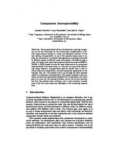
accessing the different object types, their individual instances and the corresponding attribute values.. The system was developed using C# and each component and sub-component was tested using Nunit 2.2. The schema defined by the EXPRESS file is store within a Microsoft Access database. The parsing of the IFC model is done by a line by line text reader. COMPARISON ALGORITHM A simplified version of the comparison algorithm, represented by a flow diagram, is shown in Figure 1. The work done at each step is as described below.
Figure 1: Process for the Comparison algorithm
5
Step 1: Prepare the data Let File A be an IFC Model. Import into the design tool being tested and export the model back out. Note that the model is unchanged in-between this importing and exporting process to maintain consistency. Let File B be the IFC Model exported out of the CAD tool being tested. Step 2: Load Schema and IFC models The schema is loaded into EVASYS along with the IFC models to begin the comparison process. Step 3: Comparison Process Filter for matching object types The comparison engine will select and keep all the object types which exist in both files, then store the rest as missing object types from either file. Filter for matching instances The comparison engine will repeat this sub-step for each instance of each of the matching object types. As mentioned before, the Global Unique ID (GUID) is used as the identification of an instance, so if there is an instance in File A which has the same GUID as an instance in File B, they can be considered as the same instance. However, this does not mean the attributes of both instances are identical, and thus further examination is necessary. We filter for all the instances present in both File A and File B resulting in a collection of object types matching up between two files, each of which contains collection of instances which exist in both files. Attribute comparison For each of the matching object types, we then loop through the number of matching instances. Within each loop, we retrieve the attribute values of the current instance being investigated from both models or/and the reference numbers used to establish relationships with other instances within the same model and then compare them. For simple type attributes, we check whether an attribute is equal in value to the attribute in the corresponding model. While for relationships the attributes of the instances to which the reference numbers from each corresponding isntances are compared. When there are aggregation relations the comparison process is similar. We retrieve the aggregate collection of data values or reference numbers and compare them one by one. Only if each element in the collection in a model is the same as an element in the corresponding collection in the other model, the attribute can be marked as identical. If any attribute does not have the same content in any pair of instances, that pair of instances is regarded as instances with inconsistent values; otherwise, the instances are considered consistent.
6
Determining if completely identical If there are no missing object types in either file, no missing instances in either file, and no instances that have inconsistent values, then the two models are considered identical, otherwise they are considered different. TEST FILES The models used to test this concept were a mix from previous IFC demonstrations and some exemplar buildings from CAD systems. Care was taken to ensure that during the importing and exporting process, no changes were made to the original IFC model. The comparison of two 10 MB IFC models took around 3-4 minutes. RESULTS Several buildings were run through a selection of commercial CAD systems with IFC import and export functionality. Three examples which indicate the types of differences found from the comparison are detailed below. TEST CASE 1: HOTEL MODEL File A: Hotel_Model.ifc (8,560 KB) File B: Hotel_Model_CAD.ifc (9,251 KB) Differences:
Analysis The difference in File size before EVASYS was run is quite noticeable. Opening the two IFC models using a text editor showed that File A had 147,326 lines of data while on the other hand File B had 158,225 lines. This showed that File B had introduces new instances and this was proven by EVASYS. The exported out file had introduced 338 new IfcPropertySet instances and 338 IfcRelDefinesByProperties instances. What were missing were an IfcRelAggregates instance and one IfcRelContainedInSpatialStructure.
7
TEST CASE 2: MUNKERUD HUS6 BE File A: Munkerud_hus6_BE.ifc (3,913 KB) File B: Munkerud_hus6_BE_CAD.ifc (12,923 KB) Identicals:
Differences
8
Analysis What should be noted is that the exported out IFC Model is missing 32 IfcBeam instances found in the original model. The IfcBeam type represents a beam object within a CAD drawing. TEST CASE 2: IFG 3D SAMPLE 1 File A: IFG_3D_Sample_1.ifc (3,896 KB) FileB: IFG 3D_Sample_CAD.ifc (10,455 KB) Identicals:
Differences:
Analysis: The source IFC Model of this test case was taken out of the CAD tools own sample IFC files. Despite appearing larger physically, it is missing many instances. The key instance missing in this case is IfcSite.
9
CONCLUSIONS AND FUTURE WORK Analysing the difference between an IFC file which has passed through a CAD system without modifications being made highlights a number of changes which appear within the model. The majority of the changes are fairly minor, some are even expected, but there are some significant changes (e.g., the removal of beam objects) which are unexpected. While a range of possible differences has been determined, and instances of these have been found in the compared models, this needs to be turned into a strategy which will enable design tool developers to ensure that they can maintain the semantic consistency of the data models that they manipulate. REFERENCES Atkinson, M.P., Dmitriev, M., Hamilton, C. and Printezis, T. (2000). “Scalable and Recoverable Implementation of Object Evolution for the PJama1 Platform” Persistent Object Systems, 9th International Workshop, POS-9, Lillehammer, Norway, 6-8 September, 292-314. Banerjee, J., Kim, W., Kim, H., and Korth, H. (1987). “Semantics and Implementation of Schema Evolution in Object-Oriented Databases”, Proceedings of the 1987 ACM SIGMOD international conference on Management of data. San Francisco, USA, 311-322. Eastman, C.M. (1992). “A data model analysis of modularity and extensibility in building databases”, Building and Environment, 27(2), 135-148. IAI (2005). International Alliance for Interoperability, web site last accessed 20/2/2006, http://www.iai-international.org/. Lerner, B.S. and Habermann, A.N. (1990). „Beyond schema evolution to database reorganization”, Object-Oriented Programming, Systems, Languages, and Applications (OOPSLA), Ottawa, Canada, October, 67-76. Zicari, R. (1992). “A Framework for schema updates in an object-oriented database systems” Morgan Kaufmann Series In Data Management Systems, 146-182.
10