business model obtained during the domain analysis phase and mapping it into .... define our basic system functionality represented by a software framework ...
A Framework Based Approach for Workflow Software Development Toacy C. de Oliveira, Ivan Mathias Filho, Carlos J.P. de Lucena Departamento de Informática Pontifícia Universidade Católica do Rio de Janeiro Rua Marquês de São Vicente 225 Rio de Janeiro, RJ, 22453-900, Brazil Email: {toacy,ivan,lucena}@inf.puc-rio.br
PUC-RioInf.MCC22/01 July, 2001
Abstract The purpose of Workflow Software is to provide users with an environment in which they can manipulate and control all the data and tasks involved in achieving a predefined goal (main task). Some features as user-interface, persistency, online guidance and multi-user support, are all-important and should be present in the final software, to obtain a high level of usability. It is also important that the design of the software should take place in an environment that helps the designer to deal with the large amount of definitions obtained during the domain analysis phase and the gap between these definitions and the object oriented design model. This paper describes the main features of a tool to support a method that aids the designer to develop workflow software. Keywords: Object Oriented Analysis, Framework, Reusability, Agents
Resumo O propósito dos softwares para workflow é fornecer aos seus usuários um ambiente onde eles possam manipular e controlar todos os dados e as tarefas envolvidas em alcançar um objetivo predefinido (tarefa principal). Alguns aspectos tais como interface com os usuários, persistência, tutorial on-line e suporte a multi-usuários, devem estar presentes no software final para que este seja realmente útil aos seus usuários. É também importante que o projeto do software ocorra em um ambiente que auxilie o projetista a lidar com uma grande quantidade de definições obtida durante a etapa de Análise de Domínio, além do gap semântico entre tais definições e o design orientado a objetos. Este trabalho descreve as principais características de uma ferramenta projetada para dar suporte a um método que auxilie no desenvolvimento de software para sistemas de workflow. Palavras-chave: Análise Orientada a Objetos, Frameworks, Reutilização, Agentes
1
Introduction
Workflow software (from now on called WS) can be defined as an environment in which users can manipulate all data and tasks to achieve a predefined goal [1,2,3]. To obtain a good environment, the software should be developed by refining the business model obtained during the domain analysis phase and mapping it into the source code itself. Nowadays there are no tools available to support this kind of ‘automatic’ generation. Another important aspect of the software concerns the design phase. It should be developed to support the scalability / changeability of the domain without the need for system rebuild and should incorporate features such as a graphical user-interface, persistency, online guidance and multi-user support. In this paper we report the development of a tool supported method built to help in the design of WS by mapping the models obtained during the domain analysis phase into an object oriented framework [13]. The framework implements the features listed in the above paragraph with separation of concerns [14] and uses a BNF-like structure to map the domain model into the O.O. architecture. Approaches to WS design such as WADE [2], define a business model during the domain analysis phase by using the IDEF3 [2] notation and use this model to create a simulation of the process involved. Our approach is based on the definition of a domain model using the FODA Method [6] and UML [3] to obtain diagrams that will be transformed into an object oriented framework. Actor
Actor
Domain Analysis
Use Case
NT1 ::= NT2 NT3 T1 NT2 ::= T1 T2 ......
BNF Representation BNFclass Converter
NT1Node
NT1Data
NT1TaskList
NT1Control
NT1View
WF Application
WFNode
Translation Wizard BNF Checker
WFData
WFTaskList
WFContro l
Basic Design
WFView
WFFrame
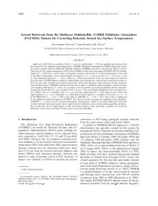
Figure 1 Steps used by the approach..
Figure 1 illustrates the steps used by the method. The first step is domain analysis. After that the method provides a translate wizard to capture aggregation and association constructs and map them into a BNF representation. The BNF-class converter will generate the basic WS Application classes and will relate them to underlying framework. In section 2 we describe the approach to obtain domain information. In section 3 we present the OO model for the WS underlying framework. In the fourth section the architecture of the tool that supports the method is presented with an example of its use in a real project. In section 5 we present the conclusions of this work.
1
2 2.1
Obtaining Domain Information Domain Analysis
The growing demand for more efficient, cheaper and delivered on schedule software systems, suggests that software development needs to be done in a environment that allows proved solutions to be modified, combined and adapted to be used in new software construction projects [4]. One of the answers provided by Software Engineering to this question can be found in the field of Domain Analysis, which can be defined as the study and organization of common aspects and variations existing among various software systems of an application domain. This process will provide a set of models describing the applications of a domain in a generic fashion, besides strategies to construct new software systems from the generic artifacts produced [6].
2.2
The FODA Method
During the late 1980’s and early 1990’s the Software Engineering community has proposed several domain analysis methods. Despite the existing differences between them, these methods are functionally equivalent, invariably exhibiting operations such as aggregation, classification, specialization and parameterization [5]. Because the existing similarities between these domain analysis methods, we have chosen the FODA method (Feature Oriented Domain Analysis) [6], developed by the Software Engineering Institute (SEI), as the method to be used in connection with our development approach. The choice of FODA can be credited to vast documentation available, including some case studies, and the tight relationship between the models produced by the FODA method and those found in the majority of the Object Oriented Analysis and Design methods (OOADM). One of the main characteristics of FODA is the process of identification of the more relevant software features of an application domain. In the FODA method, a feature is defined as an user-visible aspect or a characteristic of a software system.
2.3
The Analysis of a Domain
The FODA domain analysis process is divided into three steps: L�Context Analysis – the domain under analysis is bounded. L�Domain Modeling – the domain problems are described. L�Architecture Modeling – generic architectures implementing solutions for the problems of a domain are created. In the present work we will focus on the Domain Modeling and Architecture Modeling steps. In the FODA method, the domain model is subdivided into three distinct models which represent commonalities and existing differences between applications of a given domain. They are: L�Feature Model – which captures the main user-visible aspects of systems in a domain. L�Information Model – which captures the main abstractions, and the relationships between them, in an application domain. L�Operational Model – which models the functional and behavioral aspects of applications in a domain.
2
The Feature Model is used to represent common features, and the relationships to each others, in a family of applications. Features are classified as mandatories, alternatives and optionals. Besides usual relationships, the model also captures structural relationships such as consist of, and generalization/specialization structures. Compositional rules between features are also represented in the model. For instance, two alternatives features that must simultaneously be present in an application of a domain, have to be connected by the requires operator; while two other features that cannot simultaneously be present will be connected by mutually exclusive with operator. The Information Model is used to capture domain knowledge throughout the representation of its main abstractions and relationships. As with the Feature Model, aggregation and generalization/specialization structures will be added to the usual relationships between objects in a domain. The Information Model can be represented by any tool capable of representing the semantic aspects of data, such as the Entity-Relationship Model [7] and the class diagrams of UML [3]. The objective of the Operational Model is to identify existing functional and behavioral variation between various applications of a domain. Tools like State Diagrams and Activity Diagrams found in UML can be used with this purpose. Nevertheless, such models have to be parameterized to properly represent existing variations.
3
The Undelying O.O. Model
PROBLEM ::= REFINEMENT+
DSSProblem
GLOBAL_ANALYSIS
CHOICE
DSSRefinement
* DSSGlobalAnalysis
DSSChoice
Figure 2 BNF to class conversion.
3.1
The Basic Approach
WS deals with the manipulation of data and tasks defined to implement a specific process [1,2,3]. Analyzing this process, we can note that to improve its understandability and to obtain a system design, these tasks can be in most cases decomposed into smaller ones in a top-down fashion. This top-down decomposition can be mapped into a hierarchical structure that represents the flow of data and tasks needed to implement each specific phase of the process. The success of the design decomposition, lays on the fact that it must be based on the models obtained in the domain analysis phase. So the design should be generated as automatically as possible to guarantee its consistency. In our approach the design is obtained by analyzing domain diagrams such as use-cases [3], features models and so on, and by querying the designer to identify constructs such as composition, aggregation and communication (task flow). We use a 3
BNF-like structure to represent this decomposition. The structure can be analyzed by a BNF parse tool to guarantee the syntactic correctness of the design decomposition.
WFNode
WFData theData
CreateData CreateViewer CreateTaskList CreateControl
theTaskLis t
theContro l
WFTaskList
theViewe r WFViewer
WFControl
Figure 3 Basic WFFrame class representation. In object-oriented jargon we can say that the hierarchical structure obtained by the top-down decomposition can be seen as a hierarchy of objects (objects composition from a MAIN object), where each object, or group of objects, encapsulates the functionality and the data of a corresponding process phase. An important step in object-oriented design is class definition. In our approach, due to the natural structure and correctness of the generated BNF, we can map this structure into a set of classes that will represent the object hierarchy in the design. This mapping is produced by transforming each non-terminal symbol into a class, which will represent a corresponding node of the process hierarchy. The structure of this class can also be obtained by analyzing the production rules of the non-terminal symbols, such as it is illustrated in Figure 2. As stated before, the WS should create an environment for controlling the flow of data and tasks for a specific process. For that we use the decomposition approach to create small environments for each node of the hierarchy providing a way to create, manipulate, persist and view its local data. For this purpose we use the concept of separation of concerns [13] to define our basic system functionality represented by a software framework called WFFRAME (an acronym for Workflow Framework). In WFFRAME we have defined an abstract class called Node that represents this environment. This class has specialized components (to deal with different concerns) such as Presentation, Persistency, Manipulation and Control each one responsible for viewing, persisting, manipulating and controlling, respectively the current node data. These components are from the WFViewer, WFData, WFTaskList and WFControl classes respectively (as in [14]), and are presented in Figure 3 using the UML Notation [3]. In summary, the systems instantiated by the WFFRAME will have a hierarchy of objects (object composition), that will map the structure and behavior, needed to guide the user from phase to phase defined by the workflow process. The objects of this hierarchy are coordinated by a NodeManager object to synchronize activation and deactivation of the node and it’s components.
4
3.2
Controlling the Flow
An important issue in a workflow system is the guarantee of consistent flow of data and tasks from phase to phase. To accomplish this goal, the sequence of actions in the object hierarchy should be controlled by guaranteeing a consistent path from one node to the other. It is important to remember that this control should not remove the flexibility of the system and should not be embedded into the code. A good modeling technique to achieve this control is to define for each node in the hierarchy, a state machine to guarantee that correct actions will be carried out at the proper time (proper State). An important characteristic of state machines is that the execution of an action can take place in any allowed path, therefore improving the flexibility of the system. The state machine controls the execution exclusively in one node. To reach the inter-node control, we need to create machines to coordinate the connection between nodes. This connection coordination is close to Ducasse’s [10] active objects coordination, but in our case it applies to pairs of objects (as in DSSFRAME). The interactions between these machines will guarantee the consistency of the whole process. An important step in our approach is the design of the state machines. The design should reflect what actions can take place
Class Node DSSProblem Machine
Initial
EntryDat a
Data_Ok
EntryDat a
Choice_Done
At this time a DSSProblem object, can not handle and EntryData Message. By querying the machine, is easy to see that after the execution of Select_Solution method, the EntryData method becames available.
Select_Solutio n
Figure 4 The state machine representation used by the online wizard support. (are accepted) when a node, or its fellows, are at some state. The design is difficult because these machines cannot be automatically obtained from the domain analysis. Instead they must be ‘discovered’ by the system designer (using the models from the analysis). For this work we use the same approach used by [14] for StateMachine Design.
3.3
Agent Support
Intelligent software agents are a new paradigm for developing software applications [8,9]. These agents help users to deal with the large amount of information and tasks by executing actions on behalf of the user. This can be done in many ways: -
Reactively to users/systems inputs.
-
Proactively based on its beliefs.
-
In communication with others agents.
Analyzing the task flow as a whole we can note that, even in well-designed interfaces, users often fill lost when navigating throughout the systems interface. This is usually due to the great amount of information presented by the system and the 5
frequency of use (not daily use). To mitigate this problem, WFFrame uses a software agent to guide the user throughout the process as a task wizard (PDAs) [11] that will take care of user’s actions and verify if they are valid in the current context. By
Problem
Definition
Configuration
SetExperts
SetFacts
Defining Configuration
Solution Mediator
Expert
Experts Calculate Matrix Owner
Facts Adjust MAtrix Mediator
Obtaining Solution
Figure 5 An example of diagrams obtained from the domain analysis phase in the Pitia project. combining the state machines and the persistency support, this wizard can be easily developed in the WFFrame. To validate an user action, the wizard first queries the state machines defined for the current node to verify its state. Once receiving a positive answer, the wizard can execute data mining for value comparison. In the case of a negative answer, the wizard can report to the user the necessary steps to perform that action (Figure 4). This can be obtained by executing a sort of shortest path algorithm in the graph defined by the state machine. The wizard approach yields another benefit. Interface objects do not need to hide invalid actions from the user. The wizard controls these actions and when the user makes a mistake, the wizard can guide him, as in a self-explanatory system. To introduce this wizard in the WFFrame, we have added a new component in the NodeManager class from the AgentManager class. This object takes care of all messages by handling all nodes in the hierarchy, to validate this entry. WFNode
wfProblem wfPtDefinition aDefinition; wfPtConfiguration aCong; wfPtSolution aSolution;
wfPtSolution
wfPtConfiguration
wfPtDefinition String def; .....
String owner; Strint expert[]; String fact[];
Figure 6 Class diagrams obtained from the BNF representation.
4
The Architecture for the Method Support Tool
This section presents an overall view of the method support tool process and illustrates its use in the instantiation of the Pitia Project sponsored by the Brazilian’s Navy.
6
The first step in our approach is modeling the domain by defining a set of diagrams to represent the features model, the information model, the use-case model etc (see Figure 5). After that the designer will be queried to detect aggregation constructs such as consist-of in those diagrams, to define the BNF of the corresponding system model (figure 6). After the BNF generation, a program will analyze the BNF definition to verify its syntatic correctness. The next step is the WFFrame subclasses generation. These classes will be extracted directly from the BNF non-terminal symbols. In figure 7 we have the class diagram for some of the classes. Once the node classes are developed the next step is the construction of type dependent components for presentation, manipulation, persistency and control (the state machine) and can be seen in DSSFRAME. The last step in the WFFrame design is the internodes coordination machine development. The step is aided by the State Transition Diagrams defined during domain modeling phase. Problem ::= Definition Configuration Solution Definition ::=
string ….
Configuration ::= Owner Expert* Fact* Solution ::=
…..
Figure 7 The BNF representation for the model of figure 5.
5
Conclusion & Future Works
Due to the simplicity of the approach presented in this paper, it can be used in a great variety of WS especially in Information Systems where top-down decomposition in the design is a largely used technique. To accomplish the WS development, the designer must define its domain models and refine the BNF-like structure to define the system’s overall behavior and structure. After that the designer must create the WFNode subclasses that come from the BNF definition. Other important step is the state machine definition that must be handled carefully due to its importance in the framework. This work is an extension of the DSSFrame Framework[14] developed to support Decision Support System instantiation and was also used in the Pitia Project ( a 200 classes system developed using Borland Delphi) for the Brazilian’s Ministry of Defense. Although the approach was successful in its first use, a lot of improvements must be done and we divide them into two groups. The domain modeling approach and the framework approach. In the domain modeling phase we need to create annotations in the models to be able to capture things such as inheritance and generalization to improve the mapping from the BNF to the O.O. design model. In the framework, we need to create a wizard to identify multi-users in the use-case diagrams and to map them to the state machine support (definition of concurrency). Another important step is the state machine design. To improve its quality we will use the UML Activity Diagram to validate its development.
6
Bibliography
7
[1] Abbot, K ; Sarin, S. K. Experiences with workflow management :
Issues
for the next generation. Proceedings of
CSCW 1994. [2] Benjamin, P.C. ; Marshal,C. ; Mayer, R. J. A Workflow Analysis and Design Environment (WADE), Proceeding of the 1995 Winter Simulation Conference. [3] Booch, G.; Rumbaugh, J.; Jacobson, I.. The Unified Modeling Language User Guide. Addison Wesley, Reading, Massachusetts, Feb 1999. [4] Prieto-Díaz, R.. Historical Overview. In Advances in Software Reuse: Selected Papers from the Second International Workshop on Software Reusability, p.1-16, March 1993, Lucca, Italy. Edited by Ruben Prieto-Diaz and William B. Frakes, IEEE Computer Society Press, 1993. [5] Arango, G.. Domain Analysis Methods. In Advances in Software Reuse: Selected Papers from the Second International Workshop on Software Reusability, p.17-49, March 1993, Lucca, Italy. Edited by Ruben Prieto-Diaz and William B. Frakes, IEEE Computer Society Press, 1993. [6] Kang, K.C.; Cohen, S.G.; Hess, J.A.; Novak, W.E. and Peterson, A.S.. Feature-Oriented Domain Analysis (FODA) Feasibility Study (CMU/SEI-90-TR-21). Pittsburgh, PA, Software Engineering Institute, Carnegie Mellon University, Nov 1993. [7] Navathe, S.B.; Batini, C.; Ceri, S.. Conceptual Database Design – an Entity-Relationship Approach. Benjamin Cummings, Redwood City, California, 1992. [8] Bradshaw, J., Software Agents, MIT Press 1997 [9] Brenner, W., Zarnekow, R, Wittig, H., Intelligent Software Agents, Springer-Verlag 1998. [10] Ducasse, S., Gunter, M., Coordination of Active Objects by Means of Explicit Connectors, In Proceedings of the DEXA workshops, IEEE Computer Society Press, pp. 572-577, 1998 [11] Maes, P. Agents that Reduce Work and Information Overload, Communications of the ACM July 1994, Vol 37 No. 7 [12] Pree W. Design Patterns for Object-Oriented Software Development. Addison-Wesley, Reading Mass., 1994. [13] Silva, A.R. Programação Concorrente com Objetos: Separação e Composição de Linguagem de Padrões
Facetas com Padrões de Desenho,
e Moldura de Objetos. Dissertação de Doutorado Universidade Técnica de Lisboa – Instituto
Superior Técnico Portugal 1999 . [14] Oliveira, T.C. ; Carvalho, S.E.R. ;Lucena C.J. P.
DSSFrame - A Decision Suppot System with Agents. Techinical
Report Pontifícia Universidade Católica do Rio de Janeiro – Brazil 2000.
8