Internal report TFRT--7553, Dept. of Automatic Control, Lund, Sweden
A FRAMEWORK FOR BATCH PLANT INFORMATION MODELS Jo Simensen
Charlotta Johnsson and Karl-Erik Årzén
Department of Engineering Cybernetics, The Norwegian University of Science and Technology, N-7043 Trondheim, Norway, Fax: (+47) 73 59 43 99 E-mail:
[email protected]
Department of Automatic Control, Lund Institute of Technology, Box 118, S-221 00 Lund, Sweden, Fax: (+46) 46 13 81 18 E-mail:
[email protected] E-mail:
[email protected]
Abstract: This paper presents a combined control and information model for batch plant information. The model has been applied to a simulated scenario consisting of a multi-purpose multipath batch cell. The goal of the information model is to establish a framework for information systems that supports integrated batch plant operation. Keywords: Information models, Supervisory Control, Batch Control, Object-Oriented Modeling, Multiple Views
1. INTRODUCTION The problem area we are addressing in this paper is operation of batch process plants and information systems supporting this activity. We adopt the following definition of plant operation: Plant operation is all activities coupled to dayto-day running of a plant [Foss et al., 1995]. Plant operations, in a modern batch plant, is a complex assignment. Operating such a plant includes a wide range of activities, among others: production planning, inventory, quality control, management and on-line changes in the production. These tasks are of a diverse nature and call for a range of perspectives (views) to be solved efficiently [Foss et al., 1995]. This introduces a need for coordination and integration of the various tasks. We address these needs with an integrated batch information and control system founded on a conceptual information model. An information model is a "meta" model that depicts the problem area in terms of 1) functions, 2) domain, and 3) dynamics. The functional model describe the activities that are performed in batch plant operation and how these tasks are inter-connected. The domain model captures the static structures of a plant by its
entities and their attributes, and how these entities are connected, e.g. by pipelines. The functional and the domain models are complementary as they focus different aspects of the plant. Dynamic models couples the two former model types, relating functions with objects in the domain. All three model aspects are needed to give an adequate description of the problem area. We have implemented an information system prototype to illustrate how the ideas of an information model apply to a simulated batch cell scenario. The prototype supports integration of several operation activities and provide an architecture for a system that can grow and change. G2, an object-oriented graphical programming environment developed by Gensym Corporation, is used for implementing the prototype as well as the simulated scenario. When designing this system, great care is taken to the new ISA batch-standard called S88.01. This standard aims at giving a formal definition of the terminology, models and functionality of a batch processing cell. The physical model of S88.01 defines the hierarchical relationships between the physical units involved in batch control. The procedural model of S88.01 is also
hierarchical and tells how a procedure gradually can be broken down into smaller pieces. The physical model and the procedural model are combined to form the processing functionality. The standard also defines the different types of recipes that are needed to produce a batch and their respective contents. An introduction to batch processing and control is given in Section 2. This also include a brief summary of the batch control standard ISA S88.01. In Section 3 we give an overview of information and control systems, emphasizing systems for batch applications. The information model concept is described in Section 4. Finally, the application of the information model on a simulated batch scenario is described in Section 5.
2. BATCH PROCESSING AND CONTROL The batch mode of operation have become more important in the chemical process industry during the last decade [Parakrama, 1985]. According to Rippin [Rippin, 1991] the great majority of chemicals - by number, and probably by value if not by volume - are made in batch mode. We will here give a brief introduction to batch processing and control in general. Batch processing is a diverse area as processing in pharmaceuticals, the food industry, dyestuff or other fine chemicals have its own culture [Halasz, 1991]. Up to recently, there has been no general framework to deal with these diverse batch environments. In 1995, however, the Instrument Society of America (ISA) launched their Standard on batch control S88.01 [SP88, 1995] with the aim of setting a standard for terminology, models and functionality in batch control. In the end of this section we give an overview of S88.01.
2.1 Batch processing In general, batch processes are more economical for small scale production, as fewer pieces of process equipment are needed, and intermediate storage are not very expensive. Batch plants can be made highly flexible, and thereby well suited for manufacturing of special products. There are also processes that are not easily amenable to continuous operations. Some examples mentioned by Rosenof and Gosh [Rosenhof and Ghosh, 1987] are: 1. Processes with feedstocks and/or products that can not be handled efficiently in a continuous fashion, such as solids and highly viscous materials; 2. Processes in which the reactions are slow,
requiring the reactants to be held in process vessels for a long time (e.g. fermentation for beer and wine); 3. Processes in which only small quantities of products and/or different grades of the same product are required in limited quantities (e.g. dyestuff and specialty chemicals); 4. Processes that need precise control of raw materials and production along with detailed historical documentation (e.g. drug manufacturing). In the batch operation mode several process steps are executed in the same piece of equipment, typically some kind of reactor or vessel. During execution there is generally no product output. This in contrast to continuous processing. For the latter, operational conditions vary only as a function of geographical location. The opposite is true for batch processes where process conditions vary as function of time, while the location is not changed. When the process steps are completed, the batch (of intermediate or end-product) is transported to another process unit for further processing or storage.
2.2 Batch control Batch control projects have traditionally been among the most difficult and complex to implement [ARC, 1996]. Typically, batch control projects span over a wider scope of functionality than that required for either continuous or discrete manufacturing processes. With continuous and discrete processes, a reasonable level of automation can be attained merely by implementing basic regulatory or logic control. Batch operations typically require basic regulatory and logic control operating under sequential control; which in turn, is operating under basic recipe management in order to achieve process automation. The complexity of control within a process cell depend on the equipment available within the process cell, the interconnectivity among this equipment, the degree of freedom of movements of batches trough this equipment, and the arbitration of the use of this equipment so that the equipment can be used most effectively [SP88, 1995]. In the last few years, there have been three major initiatives with the aim to provide a common view of the batch process automation problem. Each has added new insights based on the concepts of the preceding effort. The first major effort was an outgrowth of a Purdue University workshop on batch control in the mid 1980’s,
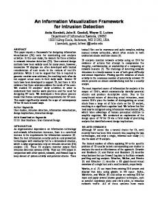
[Williams, 1988]. The second was made by NAMUR, [NAMUR, 1992]. The third major effort is sponsored by the Standards and Practices division of ISA - the International Society for Measurement and Control. Part 1 of the standard (S88.01) dealing with models, terminology, and functionality for batch control was approved by the main committee of ISA and ANSI in 1995. Part 2 will deal with data structures and language guidelines. In addition to the SP88 work in the United States, there is a simultaneous international standard being prepared under the sponsorship of the International Electrotechnical Commission (IEC). It is anticipated that IEC approval will appear soon without any substantial changes to S88.01 making it an international standard. ISA S88.01 defines a process model and a physical model representing two orthogonal viewpoints on batch control: The process view and the equipment view, respectively (cf. Figure 1). To actually manufacture a batch in a process cell the standard proposes a gradually refinement of the process model based on four types of recipes: General recipe, site recipe, master recipe, and control recipe. The general recipe is an enterprise level recipe that serves as a basis for the other recipes. The general recipe is created without specific knowledge of the process cell equipment that will be used to manufacture the product. The site recipe is specific to a particular site. The language in which it is written, the units of measurements and the raw materials are adjusted to the site. The master recipe is targeted to a specific process cell. A master recipe is either derived from a general recipe or created as a stand-alone entity by people that have all the information that otherwise would have been included in the general or the site recipe. The four recipe levels, together with equipment control, constitute the link between the process model and the physical model, denoted as procedural control in Figure 1. Procedural control is a characteristic of batch processes. It directs equipment-oriented actions to take place in an ordered sequence in order to carry out a processoriented task. Equipment control is a logical reference to the equipment and its associated capabilities. "The concept of equipment capabilities and usage of these capabilities to accomplish processing tasks is a major point of this standard" (ISA S88.01 p.31). Processing functionality described in the process model can thereby be provided through the mapping of procedural control with individual equipment entities, enabled by the procedural control capability of equipment enti-
ties. However, S88.01 part 1 has some short comings as pointed out by Niels Haxthausen [McFarlane, 1996]: It does not model the plant (e.g. connections) or a batch. What is it, and what happens to it? This and other aspects of batch process control are addressed by SP88 and several work groups within the European Batch Forum (EBF).
3. PLANT INFORMATION AND CONTROL SYSTEMS The proposed information model is closely related to plant information and control systems. We therefore include a brief introduction to this area, emphasizing systems for integrated batch control. Within the context of this paper an information system should be taken to mean the information and mechanisms used to manage, control and execute the specific function for which it exists [Keeling, 1995]. In the 1980s, the computer integrated manufacturing (CIM) pyramid symbolized the layers of technology utilized within manufacturing. This pyramid represented everything from business systems to real-time devices at the process level. According to Tony Friscia (Advanced Manufacturing Research; Boston, Mass.), the CIM pyramid is hierarchical, while most manufacturers are attending "flat" organizations and distribution of authority; it is hardware oriented, while today’s systems driver is software. Neither was the model flexible enough to meet the varying requirements within the batch industries. Hence, the hardware-based CIM pyramid is obsolete. Instead, it is being consolidated into a three layer software model: 1) The strategic level include business functions such as finance, sales, and manufacturing resources planning (MRP); 2) The tactical level contain plant
Strategic Planning
Tactical Execution
Operational Control Fig. 2
3-Level CIM model
Process Model
General Recipe
Site Recipe
Master Recipe
Control Recipe
Equipment Control
Physical Control
Process
Procedure
Procedure
Procedure
Procedure
Equipment Procedure
Process Cell
Process Stage
Process Stage
Process Stage
Unit Procedure
Unit Procedure
Equipment Unit Procedure
Unit
Process Operation
Process Operation
Process Operation
Operation
Operation
Equipment Operation
Equipment Module
Process Action
Process Action
Process Action
Phase
Phase
Equipment Phase
Control Module
Process View
S88.01 Batch Control Models and Terminology. After Haxthausen et al (1995)
management functions such as process, quality, resource, and maintenance management; 3) The operational level typically encompass process and manufacturing control functions. This "3-Level CIM model" is shown in Figure 2. The philosophy behind the creation of the "3 Level CIM" concept is that the information architecture should reflect and support the modern business architecture and insights. That is, a reduced number of management layers and empowerment of the middle management layer. The latter means providing the middle management with the right directives, information and authority to make decisions to influence their environment to improve quality, productivity and safety.
The term MES does not immediately convey a definition of the type or scope of systems which are included. By their very nature, the systems surrounding the immediate manufacturing process are heavily inter-related and it can be difficult to draw boundaries around specific manufacturing systems. Typically, the applications in the MES domain act as information brokers to exchange the information between applications at various levels of the MES-model; cf. Figure 3. Up to recently, MES has mainly received attention from information system vendors, while ISA S88.01 has received mainly
Business Management
MES
Production Management & Control
Fig. 3
AMR’s MES model
Quality Management
Traditionally, there have been two enterprise cultures that have operated independently of one another, utilizing different types of systems. Transaction based solutions, like Material Resource Planning (MRP) systems or the newer Enterprise Resource Planning (ERP) systems, for business planning at the strategic level and real-time systems for manufacturing and process control at the operational level. Manufacturing Execution Systems (MES), corresponding to the tactical level, is the "missing link" between the two domains. MES is not new, but a lot of customization used to be necessary to implement it, resulting in inflexible and expensive solutions. The term Manufacturing Execution System was coined by Advanced Manufacturing Research (AMR) in 1990 to describe the future of enterprise-wide information manage-
ment. Other industry watch groups may use different names, but MES has become the industry standard term to describe this kind of system.
Engineering
Fig. 1
Equipment View
Procedural Control
the attention of control system vendors [SP88, 1994]. Yet, the full benefits of integration can only be obtained if the concepts in S88.01 are applied at all levels of the MES model. In this context we should mention the European Batch Forum’s Work Group 1 with the objective to define "batch control" and MES integration. This effort will be continued within an EC project named BATCIME. Today’s big debate is whether a MES needs to be supplied by independent software vendors, or whether it fits better as an extension of a process control system, or the corporate-wide ERP [Basta, 1995b]. The best way to achieve this linkage is being hotly debated. One option is using a specialized MES. Another is to extend ERP systems, which manage production, financial data and product distribution, down to the plant floor. Process control systems can also be extended upwards by adding functions to connect control systems with ERPs. A final possibility is an all-encompassing system that cover all three levels of the MES-model. "In deciding whether computer systems integration should proceed from the top down or the bottom up, the bottom up approach seems to work best," said Pat Shaw, an industry analyst from AMR. "That’s where the information comes from" [Basta, 1995a]. While such a factory-floor orientation to managing the flow of information is desirable to most engineers, the demands of business may ultimately force the alternative. Several DCS suppliers have launched products based on the bottom up approach, e.g., the TotalPlant Solution from Honeywell and Advant OCS from ABB. These systems make possible data exchange with various (general) software applications to provide MES functionality. However, true integration involves more than moving data back and forth! Another "problem" is that DCS vendors put a lot of effort into obtaining compatibility with their earlier products. This is of course fortunate for customers that want to upgrade their old systems, but it seems to restrain development and the utilization of "new" technologies like Knowledge Based Systems. What is missing is: 1. An architecture which provides a united view and control of the plant, across functional boundaries; 2. An overall structure which can encompass all data into contexts useful for the various functional areas within the plant; 3. A flexible model which can grow and adjust as operational and technological needs change;
4. A model representation that aids better understanding of the totality and complexities of the plant; 5. A model representation that supports quick and effective problem solving as well as confident decision making. These are the short-comings that we address with our information model. However, organizational matters are heavily involved as well as technical. Real benefits are only obtained when people in the plant organization WANT, NEED and ACT upon information offered by the system. Our aim is to use Information Technology as an enabler to "re-integrate functionality which has been decomposed according to Taylorism" [Loos, 1995]. Not just for automation of old processes or technical support for new or reengineered processes.
4. INFORMATION MODEL Information modeling originated within the database community where it is concerned with modeling data structures for databases. Westerberg [Westerberg, 1995] describe this approach to information modeling as "pattern first, then instances". The mind set behind the creation of the World Wide Web, without the ability to extract patterns, illustrates an other approach to information modeling, namely "instances first, then patterns". Westerberg argue that the difference between the two approaches "is as subtle and important as the distinction between classbased and prototype-based inheritance in object oriented systems". We try to combine the two approaches as they both are useful. "Patterns first" for dealing with complexity and "instances first" for capturing details. Operation of a modern batch plant is a complex matter and, hence, modeling of it requires various modeling perspectives. Our information model is a model of several aspects of batch plant operation. The rationale for developing the model is to gain understanding of the problem area and to identify generic mechanisms and concepts needed to describe it. Such knowledge is valuable when developing information systems; relevant for knowledge representation as well as development of plant databases. The need for an information model with a broader scope than just process control is also identified by the European Batch Forum [Delhez, 1994]. A single uniform all-knowledge representation technique covering all aspects of a process plant does not exist, as knowledge representation and use cannot be completely separated [Årzén, 1993]. An information model is a "meta" model
that depicts the problem area in terms of 1) functions, 2) domain, and 3) dynamics, cf. Figure 4. The functional model describe the activities that are performed in batch plant operation and how these tasks are connected (by information flows). The domain model captures the static structures of a plant by its entities and their attributes, and how these entities are connected, e.g. by pipes. The functional and the domain models are complementary as they focus on different aspects of the plant. Dynamic models couple the two former model types, relating functions with objects in the domain. In addition dynamic models show temporal relationships between objects, and changes in object states. A reactor, e.g. may have the states {unreserved, batch, cleaning, maintenance}. Hence, all three model aspects are needed to give an adequate description of batch plant operation. In this section we will further describe these three model types and the modeling mechanisms in them.
Information Model
Functional Model
Fig. 4
Domain Model
Dynamic Models
Information Model Structure
The chosen approach based on three types of sub-models have some evident parallels to other modeling frameworks, e.g. the Object Modeling Technique (OMT) methodology for objectoriented development presented by Rumbaugh et al [Rumbaugh et al., 1991]. The OMT methodology uses also three kinds of models to describe a system: the object model, describing the objects in the system and their relationship; the dynamic model, describing the interactions among objects in the system; and the functional model, describing the data transformations of the system. However, these similarities are not mysterious in any way because functions, domain, and dynamics are general aspects that apply to any system.
4.1 Functional models A manufacturing plant is an artifact constructed for some purpose or function. Usually, this is to fulfill some customers needs by making products through plant operation. This entire task could be regarded as one large integrated function. However, it is probably more valid to think of it as a number of interconnected subfunctions, each one carries out a specific function. Such decomposition of function correspond
to a systems theory approach characterized by a clear definition of boundaries, an emphasis on function instead of substance, and of internal structure. The latter include the (main) routes of information interchange among functions such as the control recipe status to the scheduling activity. The exact structure, interrelationship and importance of functions will vary from plant to plant. According to this point of view, the quality of plant operation is determined by: 1) How well each separate function is performed, and 2) The interactions between these functions, as a process plant is a tightly coupled system [Foss et al., 1995], the importance of this should not be underestimated. For our investigation of functions the comprehensive functional framework proposed by Rijnsdorp [Rijnsdorp, 1991] served as a starting point. This framework applies to process plants in general and distinguish between six types of operational functions (that are clusters of activities which together make up process and production control): logistic functions, desired operation, process control, process supervision, measurement and reporting. Further, we have investigated how this general framework can be mapped onto the Control Activity Model as defined in ISA S88.01. As with the functional framework of Rijnsdorp, the majority of MES functionalities (ref. Section 3) can be mapped onto the S88.01’s Control activity model. The MES-model do, however, not only focus upon batch systems. MES is more general and applies to continuous, discrete as well as batch systems. There exist other frameworks for functional modeling than those mentioned here, e.g. Multilevel Flow Modeling (MFM) [Lind, 1987]. Different functional frameworks may overlap, as Rijnsdorp’s approach and the control activity model, or they may be complementary as illustrated by MFM and the control activity model. However, all functional models are normative. Because S88.01 is a standard within batch control we have chosen to use the Control Activity Model as a starting point for our functional model. However, the model had to be extended as the scope of plant operation is wider than just (batch) control. One of the most obvious extensions is engineering activities such as maintenance which are closely related to, but still outside, batch control. Various maintenance functions to keep process equipment, instrumentation, software, knowledge and skills in good shape is essential for all the other operational functions [Rijnsdorp, 1991], creating an important foundation for safe and effective plant operation. Another important issue in plant operation is inter-departmental coordination, such
as production vs support service. We have included organization information as another extension of the Control Activity Model to illustrate these aspects. Hence, we have expanded the boundaries of the S88.01 Control Activity Model. In Figure 5 the modified control activity model is shown, the extensions are represented by dashed rectangles. There are other crucial functions to plant operation that are not included in this functional model, such as inventory and quality control, process and product development, customer service support, and regulatory reporting and process validation. To limit our scope, somehow, we define these functions to be outside the boundaries of the functional model (and thereby, erroneously, outside the scope of batch plant operation).
Recipe Management
Production Planning and Scheduling
the interactions among these three control functions within the process control activity, and also how they interact with other activities (the grey boxes) in the control activity model.
Production Information Management
Fig. 6
The Process Control Activity
Process Management
Unit supervision: This is the control activity that ties the recipe to equipment control via process control. There are three main control functions within this control activity: 1) Acquiring and executing procedural elements, 2) managing unit resources, and 3) collecting batch and unit information.
Unit Supervision
Process Control
Organisation Information
Personnel and Environmental Protection
In the following we give a brief summary of the original components in the control activity model (those represented by solid lines in figure 5) as described in S88.01 Section 6, Batch control activities and functions. The main process control structure is represented by the control hierarchy made up of Process planning and scheduling, process management, unit supervision, and process control activities. We start with introducing the latter.
Process management: The domain of process management is the process cell. Within this control activity, control recipes are created from master recipes, each batch is defined as an entity, individual batches are initiated and supervised, resources within the the process cell are managed to resolve conflicts for their use and process cell and batch data are collected. The successful execution of a control recipe makes a batch, and process management is finished with the batch when the control recipe is complete. Process management can be discussed in terms of the following three control functions: 1) Manage batches, 2) Manage process cell resources, 3) Collect batch and process cell information.
Process control: This control activity encompasses procedural and basic control, including sequential, regulatory, and discrete control, in addition to gathering and displaying data. Process control will be distributed among several equipment entities, including units, equipment modules and control modules. Process control can be discussed in terms of three control functions: Execute equipment phases, execute basic control, and collect data represented by the white boxes in Figure 6. The figure illustrates
Process planning and scheduling: A number of different types of plans and schedules are typically needed within an enterprise, corresponding to various levels in the Physical model of S88.01. Only the scheduling needs at the process cell level, the batch schedule, are described in the standard. It identifies which batches are to be made, their order, and the equipment to be used based on the specific resources and requirements of the process cell. In addition, it deals with issues such as personnel require-
Fig. 5
Engineering
The Extended Control Activity model
ments, raw material options, and packaging requirements. The batch schedule is provided as input to the Process management. During the actual manufacturing of a batch, real time information is going in the opposite direction so that schedules can be updated within a short horizon. Scheduling is an important activity within a plant. However, finding a good feasible schedule by which costs and lead times can be reduced, is often a very complex and difficult task. Methods and tools for production planning and scheduling focus mainly on the needs of discrete manufacturing industries. Real world problems in the process industries tend to be more complex and general concepts for production planning and scheduling are hard to find [Allweyer et al., 1996], with some exceptions [Terpstra, 1996]. Recipe management: Recipe management is made up of the control functions that create, store, and maintain general, site, and master recipes. The overall output of this control activity is a master recipe that is made available to process management, which uses it to create a control recipe. Production information management: Production information management is the control activity that is involved in collecting, storing, processing, and reporting production information. All static information related to the functional model can be found in the domain model as described in the following section.
4.2 Domain model The purpose of the domain model is to organize and represent the information related to the real world entities in a process plant. The domain model captures the static structures of a plant by representing the entities in it, the information related to these entities, and how different entities are connected. Examples of typical plant domain models are traditional piping and instrumentation diagrams (P&IDs) and the Physical model of S88.01 which represent a hierarchical decomposition of the physical assets of an enterprise (in terms of enterprise, site, area, process cell, unit, equipment module, and control module). The lower part of this model is shown in Figure 1. It is generally accepted that object-oriented techniques is better suited to describe a "real world" domain than a functional approach as "object orientation offers a corresponding data structure for every physical object and thereby models the real world directly in the problem
domain" [van de Ree and Vingerhoeds, 1994]. This make the o-o approach suitable as a framework for the domain model. Generally, an objectoriented approach are characterized by the following four aspects: identity, classification, polymorphism, and inheritance [Rumbaugh et al., 1991]. Neither of these concepts are new. What makes o-o powerful is the synergy obtained when combining them. Previously, we argued that a modern batch plant is a complex system. Simon points out "the fact that many complex systems have a nearly decomposable, hierarchic structure is a major facilitating factor enabling us to understand, describe, and even ’see’ such systems and their parts" [Simon, 1982]. The discovery of common abstractions and mechanisms greatly facilitates our understanding of complex systems. Four structuring mechanisms are used for the domain models part of the information model: objects, hierarchical objects, systems, and views. [Årzén, 1993] describe how these mechanisms are utilized for implementing a multi-view plant database for Steritherm, a continuous flow process for Ultra High Temperature sterilization. Here, we apply the same structuring mechanisms in a batch environment. Objects: Objects are the primary structuring mechanism used in the domain model. "An object represent an individual, identifiable item, unit, or entity, either real or abstract, with a well-defined role in the problem domain" [Smith and Tockey, 1988]. A major strength of objects is that they represent a concept (e.g. a physical component) with its associated characteristics as a single entity. In the information model the standard object model is applied with class definitions, inheritance, attributes, and methods. The characteristic properties of an object, e.g. ’Name’ which gives the object an identity, are represented by attributes. An object may have an associated graphical representation, i.e., an icon. Objects may serve two purposes: Firstly, as basic building blocks for model development and secondly, as a practical basis for computer implementation. In this section we focus upon the first property. Simensen and Foss [Simensen and Foss, 1996] identify three types of fundamental building blocks for describing a batch plant: 1) Batch objects; 2) Resource objects (i.e. process equipment); 3) Control objects (i.e. recipes). Resource objects are the main building blocks in the domain model, while batch and control objects are related to time varying aspects and, hence, belong in dynamic models. Resources can be divided into: Process equipment, support equipment, control equipment, and raw materials.
Raw materials are crucial for making any product in the process industries. Here, we will not go deeper into this. This is a natural consequence of not including inventory control in the extended control activity model (see Figure 5). Control equipment are temperature and pressure transmitters, control valves, PIDcontrollers, etc. Support equipment are components in support systems such as the steam system, cooling-water system, and the system for pressurized-air supply. Process equipment are typically pumps, reactors, mixers, buffer tanks, and pipelines which are directly used for the processing, transporting or storing of batches. Such equipment will normally have to be cleaned after use, before it can be utilized by a new batch. Generally, process equipment are exclusive resources while support equipment can be utilized by several clients at the same time, limited by capacity, though. Our choice of equipment objects correspond to the above description of equipment items. An equipment object contains two main types of information on the equipment item. Firstly, hardware specifications like capacity and construction materials. Secondly, operation related information like references to operation procedures, statistical information, e.g. the process yield for a reactor, and equipment state. Objects may also have relations to other objects. A relationship is a logical binding between objects. There are three types of relationships: association, aggregation and generalization [Blaha et al., 1989]. Association is the most general type of relationship. An association relates two or more independent objects. For instance, a tank object can have associations to other objects such as pipes, valves and transmitters. The relations may also have graphical representation. i.e., they are drawn as connections between the objects. Connections may represent physical connections, e.g., pipes or wires, or abstract relations. Class: An object class describe a group of objects with similar properties, common behavior, common relationships to other classes, and common semantics [Rumbaugh et al., 1991]. But, why bother with classes when the concept of object is the fundamental one to modeling? Organizing objects into classes is a relationship for generalization. This is a powerful mechanism for managing complexity that is useful both for modeling and implementation. During modeling, generalization allows the modeler to group objects in a hierarchical class structure based on their similarities and differences. This represents an "is a" hierarchy. For example, a reactor with a steam-jacket is a special kind of reactor.
If the reactor is equipped with an agitator, then it is a specific kind of reactor with steam-jacket, see Figure 7. Process Equipment
Mixer
Reactor
Tank
Reactor with Steam Jacket
Reactor with Steam Jacket and Agitator
Fig. 7
Class hierarchy for a reactor.
This far, we have focused on the strong points of o-o modeling. However, it has its weak points too. A problem with class-based o-o modeling is that knowledge of a specific object may be spread out in the class hierarchy. This can to a certain degree be addressed during the modeling process by avoiding many levels in the class hierarchy. An object oriented structure is also highly application dependent leading to another problem; Knowledge of a real world entity may be spread out in several class hierarchies, because different objects represent various model perspectives of the same entity. Hierarchical objects: Aggregation is a form of relationship in which a hierarchical, or composite, object is made of components. The aggregate is semantically an extended object that is treated as a unit in many operations, although physically it is made of several components. A hierarchical object has an internal structure of, usually interconnected, objects representing the components of the object. For example, basic equipment objects such as vessel, valve, pipe, and measurement transmitter can be aggregated to form a complete process unit such as a reactor with temperature control capabilities. The composite object may have an icon and may be connected to other objects. When, however, the composite object is zoomed in upon or "opened" the internal structure of the object is shown as illustrated in Figure 8. Most interesting systems do not embody a single hierarchy; instead, we find that many different hierarchies are usually present within the same complex system. For example, a process cell may be studied by decomposing it into various systems such as process system, control sys-
pump may be water-cooled and, hence, a part of the cooling water system.
Reactor
Fig. 8
Hierarchical reactor object.
tem, steam and cooling water system. This decomposition represents a structural, or "part of" hierarchy and is orthogonal to the class hierarchy. According to Booch [Booch, 1991] "it is essential to view a system from both perspectives, studying its "is a" hierarchy as well as its "part of" hierarchy. We call these hierarchies the class structure and the object structure, respectively. Collectively, we speak of the class and object structure of a system as its architecture. The object structure is important because it illustrates how different objects collaborate with one another through patterns of interaction that we call mechanisms. The class structure is equally important, because it highlights common structure and behavior within a system". Systems: The term ‘system’ is used to denote entities that are implicated to a flow of material, energy, or information. All plants contain a number of systems. In a multi-purpose batch plant examples of systems could be the product system, the electrical system, the cleaning system, the pneumatical system, the water system, the control system, etc. The main system is the product system and the other systems can be considered as help systems that are needed for the main system to operate. Structuring plant information according to systems has many advantages. It well reflects the situation of today in the process industry. Different user groups work with different systems in the process. For example, the main system, the electrical systems, and the control system are the responsibility of the operators and process engineers, electricians, and the instrument engineers, respectively. Furthermore, different systems are normally documented separately. A system can be represented by a composite object. The internal structure of the object consists of the objects that are a part of this system. It is unusual that, e.g., a process component is a part of only one system. For example, a pump may be a part of the main system. However, the pump has a power supply and is therefore also a part of the electrical system. Furthermore, the
Views: Abstraction is the selective examination of certain aspects of a problem or domain with the goal to isolate those aspects that are important for some purposes and suppress those aspects that are unimportant. Abstraction must always be for some purpose, because the purpose determines what is and is not important [Rumbaugh et al., 1991]. Many different abstractions or views of the same thing are possible, depending on the purpose for which they are made. A view of an object represents a certain context in which the object participate and where it is necessary to represent information about the object. For example, a process component that belongs to different systems may need to have different information attached to it in the different systems, i.e., in the different views. In the database community views are mostly used in connection with how information is presented to different users of the system. Using this approach there is only one representation for an object and this representation contain all the information about the object. The different views of the object are generated by “filtering” the information contained in the object, i.e., hiding information or transforming information. Another word for these views are presentation views or user views. Views can also be used in connection with how information is represented. Here, each view of an object is represented as a separate object in the domain model. Views of this type are called representation views. In our approach both types of views are used. We have already pointed out some weak points in the object-oriented modeling framework. In addition, it is not well suited for modeling problems such as multiple classification hierarchies based on orthogonal properties, unanticipated changes in the classification, and changes in classification over time [Krogh et al., 1996]. In Section 4.3 we introduce the concept for dynamic inheritance addressing the latter problem, while the implementation mechanism of multi-view objects (cf. section 5) address the problem with knowledge related to one realworld entity distributed in several objects, according to the class hierarchy.
4.3 Dynamic models We have chosen to separate the static aspects of the batch plant and those that are concerned with time and changes. The former aspects are represented in the domain model described above, while the latter are described
by dynamic models. Recall that we approach modeling from an operational point of view, not from a design perspective as engineers often do. Obviously, there exist a whole range of dynamic models in the operational sense. We organize these dynamic models into two main categories; normative models and descriptive models. Normative models, or control models, represent how things are supposed to operate; how they are planned or designed. Typical examples are recipes, State Transition Networks [Kondili et al., 1993], and Petri nets [David and Alla, 1992]. Descriptive models on the other hand describe what actually happened, i.e. batchhistories and equipment logs. The classification into normative and descriptive dynamic models is not unique/unambiguous. For instance, a Petri net may represent a planned sequence of events as well as an actual series of events. A dynamic view of the domain model focus upon how it changes. This include temporal relations among real world entities that can be represented by associations, i.e. the temporal connection of two vessels by a pipe; Transitions applying to an entity, i.e. a batch may change from "being" a scheduled order to a control recipe; Finally, changes to the internal conditions of an entity may occur. The notion of states was introduced to object modeling to represent dynamic aspects [de Carteret and Vidgen, 1995], e.g. how class instances change over time. For instance, process equipment state can be defined by the set {unreserved, batch, cleaning, maintenance}. These states can be modeled using attributes. There is a direct, static coupling of the functional model and the domain model. The process management activity, for example, have a direct link to a process cell. Changes in the domain model, though, will normally appear as a consequence of some event, caused by some function, or as a direct result of some function itself. However, the initiation and accomplishment of a function is determined by a dynamic model such as a control recipe. In this sense, the normative dynamic models describe the dynamic control structure in a plant. By relating functions and objects, the dynamic models represent the dynamic coupling of the functional model and the domain model as illustrated with Figure 9. In addition dynamic models describe the interactions among objects in the domain model. Dynamic models encompass a wide range of models and representations. In the following we describe some of the major building blocks for building these models. These objects are batch objects, recipe objects, unit models, and historical logs.
Domain Models (e.g. SP88 Physical Model, Piping & Instrumentation Diagrams (P&ID), Plant Topology Models)
Static Relations
Dynamic Models (State Task Networks (STN), Petri Nets, Recipes)
Functional Models (e.g. Control Activity Model, Multilevel Flow Modeling (MFM), SP88 Process Model)
Fig. 9
Model Relationships.
Batch objects: As mentioned earlier, the batch is an important building block in our information model. In ISA S88.01 a batch is defined as both: 1) The material that is being produced or that has been produced by a single execution of a batch process; 2) An entity that represents the production of a material at any point in the process. In the first meaning, a batch can be modeled as an object representing the volume of material or product that constitutes the batch. In the latter ’production’ sense, a batch can be viewed as a uniquely identified object ’floating’ through the plant equipment according to a recipe. However, production is just a part of the batch’s lifecycle. Typically, the batch lifecycle start as an order for some product, cf. Figure 10. The order is then scheduled, meaning it is partitioned into one or several batches. Both the order and the scheduled batch has a relation to a general procedure for making the product. This general procedure is denoted a master recipe. During initialization the batch is assigned a unique batch number and resources that will be used for processing the batch. The batch is now best represented as an initial control recipe. However, during manufacturing it is very likely that this recipe will be modified leading to an actual control recipe. Upon completion, the actual control recipe is included as a part of the batch history. The latter is a model of what actually happened during processing of our batch, and is important for traceability and regulatory reasons. The somewhat simplified lifecycle is illustrated in figure 10. The rounded boxes illustrate various stages in the batch lifecycle, arrows represent functions, while dotted lines illustrate relations. Hence, the lifecycle model is an example of how the functional model and the domain model is coupled by a dynamic model. At any time a batch instance is in, at least, one state of the lifecycle. Different aspects of the
Order Scheduling Master Recipe
Scheduled Batch Initialization Initial Control Recipe Manufacturing
Actual Control Recipe
Batch History
Fig. 10 Simplified Batch Lifecycle
batch are important in different states. Also, a batch can be in several states at the same time, e.g. actual control recipe and batch history. How should this dynamic and multi-view aspects of a batch be modeled within an o-o framework? A possibility is to design a "super" object capable of representing all the various views of the batch. This approach can be realized by a corresponding "super" class. Another solution is to establish a single class for each relevant view of the batch (i.e. order, control recipe, batch history) and utilize them when creating batch objects through multiple-inheritance. Within both these alternatives, attributes can be used to represent the dynamic properties of the batch. However, neither of these solutions seems to model the batch lifecycle very well, as structural information is hidden in the model structure and the notion of object state is simply not powerful enough to represent the dynamic aspects. Class-based, object-oriented modeling simply do not provide suitable mechanisms for representing the batch lifecycle. A better solution is to consider a batch as belonging to different classes over time. This concept of dynamic inheritance have earlier been introduced at the programming language level [Ungar and Smith, 1991] and in o-o modeling [Krogh et al., 1996]. It is not similar to multiple inheritance as, e.g., a batch cannot be a scheduled batch and an actual control recipe at the same time. Dynamic inheritance is suitable to represent the dynamic aspects of a batch. In Section 5 we discuss an implementation mechanism addressing the problem of representing multiple views, called multi-view objects. The two concepts of dynamic inheritance and multiview objects together seems to be capable of representing a batch in a convenient way.
Recipes: A recipe is an entity that provides a way to describe products and how those products are produced. Recipes are needed for various purposes within a company. Therefore various types of recipes may exist (cf. Figure 1), including different information in varying degrees of specificity. The notion of master recipe and control recipe may illustrate this. A master recipe is a generic recipe used for tasks such as batch scheduling in a process cell, while a control recipe is uniquely connected to a single batch and the manufacturing process for this specific batch. Within the information model context recipes are dynamic models which we choose to represent by dynamic objects. We have already shown how a model of the batch lifecycle couples the functional model and the domain model. In the Batch Control Standard (ISA S88.01) this coupling is performed in another way. We briefly describe this approach (see also Section 2.2) and sketch how we can realize this coupling approach in the information model. Processing functionality described in the process model is provided through the mapping of procedural control with individual equipment entities. This is enabled by the procedural control capability of equipment entities. The tricky problem then is how to link the recipe procedure with the equipment control procedure. In S88.01 there are several alternatives: "The procedural control may be entirely defined as part of equipment control, or it may be based on procedural information passed on to the equipment entity from the recipe" (ISA S88.01 p.31). This can easily be represented within an o-o framework, where equipment entities and their capabilities are represented as objects and their methods. [Årzen and Johnsson, 1996] describe in detail various ways to realize this link within an object-oriented framework. Related to the information model, procedural control can be looked upon as the coupling of a functional model (the process model) and a domain model (the physical model), where the equipment objects in the domain model have some processing capabilities. Hence, recipebased procedural control as described in ISA S88.01 corresponds to a dynamic model in the information model framework. Historical logs: Several historical logs are needed to keep trace of production which is of overall importance in the pharmaceutical and special chemicals industries. It is of crucial importance to ensure documentation and traceability on the process equipment side, as well as on the product side. Equipment related examples are equipment logs that keep references
to all batches processed by a particular piece of equipment, and maintenance logs describing when a piece of equipment has gone through maintenance, what has been done by whom and the planned time for the next maintenance operation. Batch histories, on the other hand, are product related and keeps a record of the total processing of a batch. All information on discrete events, like time-stamps for start and stop of process stages, results from laboratory analysis, and product related information such as volumes and references to raw materials, are included in the batch history. Process data from continuous processing is also included. The various types of historical logs are in fact what we denote as descriptive dynamic models. In the information model, we represent them by dynamic objects. Unit models: Dynamic models of unit processes are also represented as dynamic objects in the information model. A typical unit model example is a reactor model, either based on "1. principles" modeling or black-box techniques. Such models can be utilized for control purposes, simulation, optimization, etc., and they are well known within the process systems engineering community. We will therefore not discuss these any further. State-Task-Networks: A convenient representation of process and recipe information is the State Task Network (STN) proposed by [Kondili et al., 1993]. This is a general framework that apply to continuous processing as well as batch processing. Within STN task nodes (rectangles) represent process operations and state nodes (circles) represent process material, e.g. raw materials, intermediates, and product. The physical plant is represented as a set of equipment units capable of performing the operations defined by the tasks in the STN. Examples of such process tasks are ’mix’, ’heat’, ’store’, ’crystallize’, ’react’, etc. The relationship between processing units and tasks can be many-tomany. The process sequence is illustrated by arcs between state and task nodes as illustrated in Figure 11. STN can be used for both recipe/process design and scheduling. In the original version STN is a fairly coarse process description as, for instance, transfers of materials are assumed to be instantaneously. In many processes, though, transfer operations take a considerable portion of the total (production) cycle time. Barbosa and Macchietto (1994) have discussed how this problem may be solved by introducing extra tasks and nodes in the STN model.
Fig. 11 State-Task-Network
5. A PROTOTYPE IMPLEMENTATION An information system founded on an information model should support all functions described by the functional model, all static information should be represented in the domain model, and finally, temporal and transient aspects should be dealt with as described by the dynamic models. We have implemented an information system prototype to illustrate how the ideas of an information model apply to a simulated batch cell scenario. The extended control activity model is used as a navigation metaphor in the prototype. The domain model is established by combining the concepts described in section 4.2 and implementation mechanisms such as multi-view objects. The domain model structure is used both for structuring the plant database (representation view) and as user interface. Dynamic models, such as the batch lifecycle and procedural control, form the basis for integration of the functional model and the domain model, and thereby also for batch control. The information model based prototype supports integration of several operation activities and provide an architecture for a system that can grow and change. The prototype is implemented in G2, an object-oriented graphical programming environment, developed by Gensym Corporation. The prototype is based on a single information repository (or plant knowledge base). Such a storage may be actual, in the form of a data warehouse, or virtual, in the sense that different servers in a computer network make information available as if they were part of an overall repository. In a real time application area the latter solution is to prefer as it give better control system performance. Multi-view objects is a mechanism that support the implementation of a virtual data warehouse [Årzén, 1993] as described in the following. As explained in section "Domain model" the interesting properties of an object will vary in different contexts. Properties that are not relevant
to the task at hand should not be visible in a user view as they will be regarded as "noise". On the other hand, all information on an object should be grouped together to structure the plant knowledge base and to avoid duplication of data and the consistence problems that follows. A multi-view object act as a handle on all the “ordinary” objects that represent the same physical or abstract entity in different contexts.
5.1 A Batch Scenario In the prototype implementation the information model is applied to a scenario consisting of a flexible multi-purpose batch cell. The cell consists of raw material tanks, mixers, buffers, batch reactors, and product tanks. The units are interconnected through valve batteries. A schematic of the batch cell is shown in Figure 12.
object-oriented programming and high-level (coloured) Petri nets [Jensen and Rozenberg, 1991], has been defined and implemented [Årzén, 1996] in G2. The scenario was developed to show how High-Level Grafchart can be used for recipe representation, recipe execution, and resource allocation, [Årzen and Johnsson, 1996], [Johnsson and Årzén, 1994], and [Johnsson and Årzen, 1996], according to the ISA S88.01 models. This approach is used for the recipe representation also in the information model. The information model is structured using objects, views, and systems according to the previous chapter. Both user views and representation views are used. One user has been defined, who can be viewed as a “super-user” that performs all the tasks that in a real plant would be divided between operators, process engineers, production engineers, maintenance personnel, etc. The different interfaces that the user has available constitute the different user views in the systems.
5.2 User views
Fig. 12 The batch cell
A real-time simulation of the batch cell is used instead of a “real” batch cell. The simulator contains mass balance models, energy balance models and chemical reaction models. The simulator uses three reactants: A, B and C, and two different products, D and E, can be produced. A control system structured according to the proposed information model implements the different layers of the control activity model, see Section 4.1, and the different domain and dynamic models used in the different layers. The control system is connected to the batch cell through a simulated I/O interface. The scenario was originally developed in the Grafchart project. There High-Level Grafchart, an Grafcet model extended with concepts from
Plant operation, in a modern batch plant, is a complex "task" (cf. the functional model). Minsky (1968) argue that in such a complex problem area, human beings can never cope with many details at once. At each moment one must work within a reasonable simple framework. Any problem that a person can solve is worked out in a small context and the key operations in problem solving are concerned with finding or constructing these working environments. A batch plant information system based on this philosophy would offer different support for various operational functions in form of user views. A user view is a context dependent system interface that give access to both the information and the functional tools needed to perform the various tasks included in an operational function. The information presented in views may be of various nature, i.e. dynamic/static, detail vs overview, functional vs descriptive, etc. The user views are organized according to the control activity model, see Figure 13. Each activity corresponds to one main user view. This user view presents the information and interaction objects necessary for performing the activity. The control activity model also is used as a navigation metaphor. The user switches user view by clicking on the corresponding activity in a control activity model icon. Recipe Management: When selecting "Recipe Management" in the control activity model a window pops up showing the hierarchical rela-
Fig. 15 Master recipe. Fig. 13 The extended control activity model.
tionship between the different recipe types. If e.g. the Master Recipe is chosen a window pops up showing all existing master recipes, see Figure 14. Each product, i.e. product D or E, can be produced in four different way, each one giving a certain product-quality.
tivity where planning and scheduling of batches take place. In the current implementation all planning and scheduling is done in a very simple manner i.e. FIFO. When selecting "Production Planning and Scheduling" a window pops up allowing the operator to chose between schedule, orders, new D, new E or STN. Selecting "New D" or "New E" allows the operator to make a new order of product D or E respectively, see Figure 16. The operator types in the desired amount of the product, the name of the customer and the duedate.
Fig. 14 Recipe management view.
The master recipe is a unique specification of how to produce a product, by selecting a master recipe the detailed description of the recipe can be seen. Apart from the production-procedure each master recipe also contains administrative information, formula information and equipment requirements, see Figure 15. From this window it is also possible to create a new master recipe and to see the StateTransition-Network (STN) for the different products. Production Planning and Scheduling: Production planning and Scheduling is the control ac-
Fig. 16 Scheduling view.
If selecting "Schedule" a list of the scheduled batches shows up. The order made in Figure 16 is scheduled and shown in Figure 17. As can be seen the order is broken down into four batches and equipment has been pre-assigned to each batch. If selecting "Orders" a list of the not yet sched-
uled but ordered batches shows up and selecting "STN" allows the operator to see the StateTransition-Net for each product.
a token the operator can define the name of the batch, the control recipe, and the position of the batch in the plant. In Figure 19 the batch cell is shown together with the state chart. As can be seen in the state chart there is one batch currently in process and one batch that has been completed. From the schematic of the batch cell one can see that the completed batch is located in product-tank D and the batch currently in process is located in one of the mixers.
Fig. 17 List of scheduled batches.
Production Information Management: When selection the Production Information Management a window pops up giving the operator the choice to see either a list of the batches currently under production, a list of the history for completed batches or the equipment histories. In Figure 18 the batch named "D1-1", created in Figure 17, is ready and the history of this batch is shown. In the batch history there is information about the master recipe, the initial control recipe and the actual control recipe, i.e. the initial recipe plus changes made under production. There is also an event list including logs.
Fig. 18 Information view
Process Management: In the Process Management activity the schematic of the batch cell is shown together with a state chart showing the state of the scheduled batches. A batch can be either "Ready-to-start", "In-process" or "Completed". In the state chart a batch is represented by a token. The color of the token depends on the product that will be produced. Substance D is represented with a green token and substance E with a red. Batches that are scheduled can get started by clicking on the "Init-batch" button placed next to the state chart. By clicking on
Fig. 19 Process management view
Unit Supervision: In the Unit Supervision activity the operator can get information about the different operations that a unit can perform, i.e the different methods assigned to a unit. A mixer can e.g perform the following operations: charge, agitate and discharge. The operator can also get information about the batch currently using a unit and the corresponding control recipe. Process Control: In the Process Control activity the schematic of the batch cell is shown. As the batch travels through the plant its actual position is high-lighted. By clicking on any of the units the internal structure of this unit shows up. Each unit has on-off valves at the inlets and the outlet. The operator can open and close these valves manually, also pumps can be turned on and off manually. The units all have sensors for measuring level, temperature and pressure. When clicking on any of the sensors a trend curve of the measured signal is shown, see Figure 20. Some of the sensor are connected to PID-controllers. The controllers are used to control e.g. the level or the temperature in a unit.
Organization Information: The organization information is not included in the control activity model of S88.01. However, it has been added in this batch plant information model since it is an important source of information. Here, the
Fig. 22 CIP system part of engineering view.
Fig. 20 Process control view
operator can find out e.g. the name and the skills of different persons working at the batch plant, see Figure 21.
Fig. 21 Organization view
Personal and Environmental Protection: The personal and environmental protection model is outside the scope of SP88.01 and of our information model. Engineering: In the engineering view information about the maintenance of the units and different support systems such as electrical, steam and clean-in-place (CIP). The CIP system is organized in the same way as the plant except that the storage and product tanks are not included since these units do not use the CIP system. In Figure 22 the schematic of the CIP system is shown.
5.3 Recipe representation and execution The recipe representation and execution is based on Grafchart and High-Level Grafchart. The main difference between a Grafchart function chart and a High-Level Grafchart function chart concerns the nature of the tokens that indicate whether a step is active or not. In
Grafchart the token is a boolean indicator that simply indicates that the step is active in the same way as in ordinary Grafcet. In High-Level Grafchart the tokens are objects that contain information. Also the tokens may themselves contain function charts. The master recipes are represented as Grafchart function chart objects. The procedure of the recipe is represented graphically by interconnected Grafchart objects (steps, transitions, macro steps, procedure steps, etc). In the current implementation the recipe is decomposed into recipe phases. Each recipe phase is represented by a procedure step that calls a corresponding equipment phase in the unit process where that part of the recipe eventually will execute. The equipment and formula information of the recipe is stored as attributes of the function chart object. The values of these attributes can be accessed from the steps and transitions of the recipe procedure. When a batch is created a control recipe for that batch is created by copying the associated master recipe. The equipment that has been assigned to the batch becomes the values of the equipment attributes of the control recipe function chart. When a batch is started the control recipe function chart for that recipe is initiated, i.e., the initial step of the control recipe is activated. When a control recipe phase becomes active a call is made to the corresponding equipment phase in the unit process where that recipe phase should execute. The equipment phase is represented by a Grafchart method of the unit process. The Grafchart method consists of a step/transition sequence. In the steps control actions are performed, e.g., valves are opened or closed, pumps are started or stopped, and regulator setpoints are changed. The execution of a control recipe phase is finished when the call to the equipment phase returns. Then the execution of the control recipe continues. The situation is shown in Figure 23. The control
Control Recipe
Representation View
Calling the charge method of reactor R1
User View
Fig. 23 Control recipe calling an equipment phase
Fig. 25 User view versus representation view
may or may not be a one-to-one mapping between user views and representation views. An example where there is a one-to-one mapping is shown in Figure 25. The navigation metaphor is shown in the upper left corner of the user view.
Fig. 24 High-Level Grafchart for process supervision.
recipe is shown to the left. The control recipe phase Charge calls the charge method of reactor R1. This reactor is the value of the reactor attribute of the recipe and is accessed through the sup.reactor reference. High-Level Grafchart is used to indicate the status of the process units in the cell. A process unit can be unreserved, reserved by a batch, in CIP, or taken out of service due to maintenance. In the high-level function chart in Figure 24, each process unit is represented by a token object. The step that the process unit is contained in shows the status of the process unit. When a process unit has been used by a batch, CIP must be performed. In the CIP procedure step the CIP method of the process unit is called.
5.4 Representation views The aim of the user views is to present information contained in the database to users in an optimal way with respect to the tasks that the users should fulfill. The aim of the representation views is to structure the information within the database in a “natural” way. There
Each physical (or abstract) entity is represented by a number of database objects. Each of these database objects constitutes one view of the physical entity, i.e., it represents the entity in a certain context. The different views of a physical entity may have different attributes, different internal structure, and different relationships to other entities. The different views of the same physical entity are held together by a multi-view object. This acts as a handle that contains links to all the different views of the object. It also defines the views of the object and the attributes that are common to all views of the object. G2 does not directly support multi-view objects. The desired functionality is mimiced using ordinary objects and relationships between objects. The different contexts that a physical object is a part of are often decided by the different systems in which the object participates. In the prototype only two systems have been modeled: the product system and the CIP system. Additional systems could be the electrical system, the water system, the steam system, etc. Multi-view objects are used in the information model in different ways. The entire batch cell is modeled as a multi-view object. The different unit processes are also modeled as multiview objects. The batch cell multi-view object has three views: the product view, the CIP view and the maintenance view. The product view of the batch cell is an hierarchical object that inter-
Batch Cell Multi-view object
Batch Cell: CIP view
mation system based on the model has been implemented in G2. The system runs against a real-time simulation of a flexible batch cell. Batch Cell Product view
R1 Multi-view object
Fig. 26 Batch cell multi-view object with product view and CIP view.
nally consists of objects representing the product view of the unit processes of the cell, i.e., the product view of the batch cell resembles the process diagram of the cell. The product views of the unit processes are objects that contains the control modules of the unit processes as attributes. For example, the product view of one of the batch reactors has object attributes representing the inlet valve, outlet valve, pump, PID-controllers, and sensors. The view also contains the equipment phases of the reactor, e.g., charge, heat, cool, discharge, etc, represented as Grafchart method attributes. The CIP view of the cell is also an hierarchical object. It contains the CIP specific process equipment (the CIP tank unit) and the CIP views of the unit processes of the cell. These CIP views contain the CIP valves of the units and the CIP phases of the units. The maintenance view of the cell contains maintenance information related to entire cell. It also contains the maintenance view of each unit process in the cell. These views contains maintenance information pertaining to the individual unit, e.g., operation counter for each control equipment of the unit, information about when maintenance last was performed, etc. The batch cell multi-view object is shown in Figure 26. The multi-view object representing reactor R1 is also shown.
6. CONCLUSION An information model for batch processing has been proposed. The model is decomposed into functional, domain, and dynamic models. The proposed modeling mechanisms represent the various aspects of the problem area in a natural way. The model also conforms with the ISA S88.01 standard. A prototype of an infor-
7. REFERENCES Allweyer, T., P. Loos, and A.-W. Scheer (1996): “Requirements and new concepts for production planning and scheduling in the process industries.” In Submitted to I-CIMPRO’96, Eindhoven, Netherlands. ARC (1996): “Batch process automation strategies.” Industrial Automation Strategies for Executives. Automation Research Corporation. Årzén, K.-E. (1993): “Using multi-view objects for structuring plant databases.” Intelligent Systems Engineering, 2:3, pp. 183–200. Årzén, K.-E. (1996): “Grafchart: A graphical language for sequential supervisory control.” In Proc. of the IFAC World Congress 1996. Årzen, K.-E. and C. Johnsson (1996): “Objectoriented SFC and ISA-S88.01 recipes.” In Proc. of the World Batch Forum, Toronto. Basta, N. (1995a): “A computer RX for batch processes.” Chemical Engineering, July, pp. 161–164. Basta, N. (1995b): “Finding the right glue for production management.” Chemical Engineering, August, pp. 125–126. Blaha, M., N. Eastman, and M. Hall (1989): “An extensible ae&c database model.” Computers Chem. Engng, 13:7, pp. 753–766. Booch, G. (1991): Object Oriented Design - with applications. Benjamin/Cummings. David, R. and H. Alla (1992): Petri Nets and Grafcet. Prentice Hall. de Carteret, C. and R. Vidgen (1995): Data Modelling for Information Systems. Pitman Publishing. Delhez, J. (1994): “European batch forum workgroup 1 charter and objectives (draft).” Foss, B., R. Klev, M. Levin, and K. Lien (1995): “Integrated production systems for the process industries.” In Submitted to The First World Congress on Integrated Design and Process Technology. Halasz, L. (1991): Modelling of Batch Processing in AI Environment. PhD thesis ETH No. 9555, ETH, Zurich, Switzerland. Jensen, K. and G. Rozenberg (1991): High-level Petri Nets. Springer Verlag.
Johnsson, C. and K.-E. Årzén (1994): “Highlevel Grafcet and batch control.” In Symposium ADPM’94—Automation of Mixed Processes: Dynamical Hybrid Systems, Brussels, Belgium. Johnsson, C. and K.-E. Årzen (1996): “Batch recipe structures using High-Level Grafchart.” In Proc. of the IFAC World Congress 1996. Keeling, G. (1995): “Manufacturing execution systems.” In Proceedings of the European Batch Forum, Dublin.
Simensen, J. and B. Foss (1996): “A concept for modelling batch plant operation.” In procedings of European Symposium on Computer Aided Process Engineering-6 (ESCAPE-6). Simon, H. (1982): The Sciences of the Artificial. MIT Press. Smith, M. and S. Tockey (1988): An Integrated Approach to Software Requirements Definition Using Objects. Boeing Commercial Airplane Support Division, Seattle, WA. p. 132. SP88 (1994): “Sp88 mes task force europe position document.”
Kondili, E., C. Pantelides, and R. Sargent (1993): “A general algorithm for scheduling batch operations.” Chomputer and Chemical Engineering, 17:2, pp. 211–227.
SP88 (1995): “Batch control.” Instrument Society of America.
Krogh, B., J. Levy, A. Dutoit, and E. Subrahmanian (1996): “Strictly class-based modeling considered harmful.” In Proc. of 29th Hawaii International Conference on Systems Sciences.
Ungar, D. and R. Smith (1991): “Self: the powe of simplicity.” LISP and Symbolic Computation, 4:3, pp. 187–205.
Lind, M. (1987): “Multilevel flow modeling - basic concepts.” Technical Report, Institute of Automatic Control Systems, Technical University of Denmark. Loos, P. (1995): “Information management for integrated systems in process industries.” In submitted to 5th IFAC Symposium on Joint Design of Technology and Organisation, Berlin. McFarlane, T. (1996): “Ebf/sp88 joint meeting minutes.” In EBF Proceedings, p. 4, Imperial College, London. NAMUR (1992): NAMUR-Emphehlung: Anforderungen an Systeme zur Rezeptfaheweise (Requirements for Batch Control Systems). NAMUR AK 2.3 Funktionen der Betriebs- und Produktionsleitebene. Parakrama, R. (1985): “Improving batch chemical processes.” Chemical Engineer, September. Rijnsdorp, J. (1991): Integrated Process Control and Automation. Elsevier. Rippin, D. (1991): “Batch process planning.” Chemical Engineering, May, pp. 100–107. Rosenhof, H. and A. Ghosh (1987): Batch Process Automation. Van Nostrand Reinhold. Rumbaugh, J., M. Blaha, W. Premerlani, F. Eddy, and W. Lorensen (1991): ObjectOriented Modeling and Design. Prentice Hall.
Terpstra, V. (1996): Batch Scheduling. PhD thesis, Technische Universiteit Delft.
van de Ree, R. and R. Vingerhoeds (1994): “Object orientation in process control.” In Proceedings of Process Systems Engineering (PSE’94), pp. 1175–1180. Westerberg, A. (1995): “Distributed and collaborative computer-aided environments in process engineering design.” In Preprints of Intelligent Systems in Process Engineering (ISPE’95). Williams, T. (1988): “A reference model for computer integrated manufacturing (cim).” In International Purdue Workshop on Industrial Computer Systems, ISA.