Dec 5, 2003 - Matthieu Berdugo has a working interested in HVAC systems, and ..... Scheduling becomes more accurate if a step-by-step method is followed.
A Framework for MCDM Method Selection Friday, December 05, 2003
Nathan Rolander Ashley Ceci Matthieu Berdugo
Prepared for: Dr. Farrokh Mistree & Matt Chamberlain
Georgia Institute of Technology
Abstract
This report pertains to the systematic approach to selection. This is accomplished through an augmentation of the Pahl and Beitz systematic design approach. The three phases of Pahl and Beitz addressed are clarification of task, conceptual design, and embodiment design. In addition we have included some external augmentations to support this augmented method. This developed method is then tested for utility through its application to a selection problem. This selection involves the choice of the most appropriate cooling system for Nathan Rolander’s new research lab facility. This process is documented in detail as an example. Finally, learning and future directions are addressed, as is our self-grading scheme. Appendices include research summaries, and individual Q4S work for background relevance.
12/14/2004
1
Contents
Abstract_______________________________________________________________ 1 Contents ______________________________________________________________ 2 Glossary of Terms ______________________________________________________ 9
Section 1: Introduction ___________________________________________
10
Team Introduction _____________________________________________________ 10 Group Members ____________________________________________________ Nathan Rolander ___________________________________________________ Ashley Ceci_______________________________________________________ Matthieu Berdugo __________________________________________________
10 10 10 10
Project Introduction____________________________________________________ 11 Data Centers & Thesis _______________________________________________ 11 Project Goals _________________________________________________________ 13 Group Q4S_________________________________________________________ Nate’s Relation to Personal Q4S_______________________________________ Ashley’s Relation to Personal Q4S_____________________________________ Matthieu’s Relation to Personal Q4S ___________________________________
13 13 13 14
Realization of Group Q4S Through Data Centers HVAC Selection __________ 14 Group Vision of 2020 ________________________________________________ Manufacturing_____________________________________________________ Information _______________________________________________________ Marketing ________________________________________________________ People ___________________________________________________________ Resources ________________________________________________________ Research & Development ____________________________________________
15 15 15 16 16 17 17
PEI Diagram & Plan of Action ___________________________________________ 18
Section 2: Research of Selection Methods _______________________
21
Why Selection is Important ______________________________________________ 21 Most Important phase of design _______________________________________ 21 Incorrect Decisions __________________________________________________ 21 Finding Focus ______________________________________________________ 22 Defense of a Systematic Method _______________________________________ 23 Tools ________________________________________________________________ 25 What tools are in use today? __________________________________________ 25 12/14/2004
2
What tools will be required in the future? _______________________________ 29 Research _____________________________________________________________ 31 Methods ___________________________________________________________ Structure of a method _______________________________________________ Features __________________________________________________________ Different approaches________________________________________________ DM related Characteristics ___________________________________________ Problem related Characteristics _______________________________________ Solution related Characteristics _______________________________________
31 31 32 35 36 36 36
Critiques___________________________________________________________ 39 Summary of findings_________________________________________________ 39
Section 3: Group Augmentation of Pahl and Beitz ______________
41
Critical Evaluation of Base P&B Method___________________________________ 41 The Base P&B Method _______________________________________________ Planning and Clarifying the Task ______________________________________ Conceptual Design _________________________________________________ Embodiment Design ________________________________________________ Detail Design _____________________________________________________
41 43 43 44 44
Critical Evaluation of Base Method ____________________________________ Setting Initial Direction - Clarification of Task ___________________________ Selecting Concepts - Conceptual Design ________________________________ Selecting Layouts - Embodiment Desgin ________________________________
45 47 48 49
External Augmentation _________________________________________________ 50 Ethics _____________________________________________________________ 50 Responsibility to Those you’re working for: _____________________________ 50 Responsibility to Those you’re Working With, or under: ___________________ 51 Communication _____________________________________________________ 51 Automation of Design Systems ________________________________________ Integrated Software Data Exchange ____________________________________ Integrated Hardware Communication___________________________________ Information Depots _________________________________________________
51 52 52 52
Clarification of Task ___________________________________________________ 54 Structure of Formalized MCDM Selection Process________________________ 54 Selection Methods Requirements List___________________________________ Define Desired Objectives for Selection_________________________________ Select Evaluation Criteria ____________________________________________ DM Related Characteristics __________________________________________ Method Related Characteristics _______________________________________ Problem Related Characteristics _______________________________________ Solution Related Characteristics _______________________________________ 12/14/2004
55 55 56 57 57 58 59 3
Independence of Categories __________________________________________ 59 Justification of Criteria ______________________________________________ 60 Phase Checklist _____________________________________________________ 61 Conceptual Design _____________________________________________________ 62 Determine available Techniques _______________________________________ 62 "Whether" Decisions If you are trying to decide whether to dismiss an employee "for cause", or whether to split the company stock, or whether customers like a new package design for a product, then you have a "whether" decision. "Whether" decisions usually have binary solutions:_________________________________ 62 Selection of Appropriate MDCM Methods ______________________________ 66 Justification _______________________________________________________ 66 Construction of Matrices _____________________________________________ 67 Weighting of Characteristics__________________________________________ 67 Justification _______________________________________________________ 67 Evaluate Matrices ___________________________________________________ DM Evaluation Matrix ______________________________________________ Method Evaluation Matrix ___________________________________________ Problem Evaluation Matrix___________________________________________ Solution Evaluation Matrix___________________________________________ Justification _______________________________________________________
68 68 68 69 69 70
Phase Checklist: Conceptual Design ___________________________________ 70 Embodiment Design____________________________________________________ 71 Analyze and Select the Technique ______________________________________ 71 Applying the Selection Technique ______________________________________ 72 Evaluation of Individual Matrices _____________________________________ 72 Sensitivity Analysis __________________________________________________ 74 Changing the highest weighting value:__________________________________ 74 Changing the top ranked MCDM method: _______________________________ 74 Phase Checklist: Embodiment Design __________________________________ 75 Detail Design _________________________________________________________ 76 Form Development __________________________________________________ Criteria Justification Form: ___________________________________________ MCDM Technique Justification Form:__________________________________ Matrix Value Scale Justification Form: _________________________________ Matrix Weighting Scale Justification Form:______________________________
76 76 76 76 77
Ethics _____________________________________________________________ Individual ________________________________________________________ Team ____________________________________________________________ Company _________________________________________________________
77 77 78 78
Phase Checklist _____________________________________________________ 78 12/14/2004
4
Integration into Pahl and Beitz ___________________________________________ 79
Section 4: HVAC Application of Augmented Pahl and Beitz ___
81
Clarification of Task ___________________________________________________ 81 Introduction________________________________________________________ 81 Task Analysis_______________________________________________________ Determine Goals of Project___________________________________________ Geometry Constraints _______________________________________________ Heat Rejection & Flow Constraints ____________________________________
81 81 82 83
Requirements List___________________________________________________ 84 Phase Checklist: Product Planning And Clarification of Task ______________ 86 Conceptual Design _____________________________________________________ 87 HVAC Attention Direction____________________________________________ 87 Data Center Cooling Systems _________________________________________ 87 CRAC Unit Specifications ___________________________________________ 87 Phase Checklist: Conceptual Design ___________________________________ 88 Embodiment Design____________________________________________________ 89 Selecting the MCDM Method _________________________________________ 89 1. Define the desired objectives or purposes that the MCDM techniques are to fulfill based on the requirements list for techniques. ____________________________ 90 2. Select Evaluation criteria that relate technique capabilities to objectives. _____ 90 3. List and Specify MCDM techniques available for attaining the objective of modeling the multicriterion problem on hand through the use of the method attribute tree diagram. ______________________________________________________ 92 4. Determine technique capabilities or the levels of performance of a technique with respect to the evaluation criteria be setting up and solving a multicriterion problem. _________________________________________________________________ 96 5. Construct an evaluation matrix (techniques vs criteria array), the elements of which represent the capabilities of alternative techniques in terms of the selected criteria. __________________________________________________________ 97 6. Analyze the merits of the alternative MCDM techniques and select the most satisficing technique._______________________________________________ 100 7. Application of the selected MCDM technique._________________________ The Prospective Methods:___________________________________________ PreSelection _____________________________________________________ Selection DSP ____________________________________________________ Selection-Selection DSP (and Coupled SSDSP) _________________________ The Selection ____________________________________________________
103 103 104 105 106 107
Justification _______________________________________________________ 114 8. Verify that selection is indeed representative of the overall goal, and that it meets the established requirements set forth in the project requirements list. ________ 114
12/14/2004
5
9. Signing of decision by all members involved in process, ascertaining that they accept the responsibility of this decision and the resulting design path that is chosen. ________________________________________________________________ 115
Section 5: Summary of Findings ________________________________
116
Project Accomplishments_______________________________________________ 116 Review of Work to Date _____________________________________________ 116 Discussion of Discoveries ____________________________________________ 117 Limits of Augmentation _____________________________________________ 117 Hazelrigg Verification & Validation __________________________________ 117 Group Decision Arrows Theorem_____________________________________ 120 The Validation Square ______________________________________________ 122 How we would we continue __________________________________________ 123 Automation ______________________________________________________ 123
Section 6 : Self Grading _________________________________________
125
Utility and Value _____________________________________________________ 125 Learning ____________________________________________________________ 126 Project Management________________________________________________ 126 Time Management _________________________________________________ 126 Team Interactions __________________________________________________ 126 Grading Scheme______________________________________________________ 127 Grading Sheet________________________________________________________ 128 References __________________________________________________________ 129 Appendix A: Individual Visions _________________________________________ 130 Ashley Ceci______________________________________________________ 130 A0 Goals__________________________________________________________ 130 Personal Question for the Semester ___________________________________ 130 Personal World of 2020 _____________________________________________ 130 Group Project _____________________________________________________ 132 Nathan Rolander __________________________________________________ 134 A0 Goals__________________________________________________________ 134 Personal Question for the Semester ___________________________________ 134 Group Project _____________________________________________________ 134 Personal World of 2020 _____________________________________________ 136 Matthieu Berdugo _________________________________________________ 138
12/14/2004
6
A0 Goals__________________________________________________________ 138 Personal Question for the Semester ___________________________________ 138 Personal World of 2020 _____________________________________________ 138 Group Project _____________________________________________________ 140 Appendix B: Paper Summaries __________________________________________ 142 Hierarchical Selection Decision Support Problems in Conceptual Design Selection in the Conceptual Design of Aircraft________________________________________ 142 PreSelection _______________________________________________________ 143 Selection DSP______________________________________________________ 144 Selection-Selection DSP (and Coupled SSDSP) __________________________ 145 A Select Overview of MCDM Techniques__________________________________ 147 Selection/Decision Methods __________________________________________ 148 Choosing The “Best” Multiple Criteria Decision-Making Method ______________ 150 Introduction_______________________________________________________ 150 Importance of the selection problem___________________________________ 151 Alternative approaches to the selection problem_________________________ 151 Using a classification tree: __________________________________________ 151 Using an MCDM Expert System: _____________________________________ 152 Steps in the development of an MCDM expert system ____________________ 152 An interactive decision support system for multicriteria decision aid ____________ 154 A Procedure for Selection of a Multiobjective Technique with Application to Water and Mineral resources. ____________________________________________________ 156 Classification of Criteria: ____________________________________________ 156 Classification of problem: ___________________________________________ 156 Classification of the method: _________________________________________ 156 Classification of decision maker:______________________________________ 157 Importance of criteria: ______________________________________________ 157 Facts and Fictions about the Analytic Hierarchy Process (AHP) _______________ 159 Introduction_______________________________________________________ 159 Facts & Fictions____________________________________________________ 159 Validation of Engineering Design Alternative Selection Methods ______________ 161 Introduction_______________________________________________________ 161 Arrow’s 4 properties of selection methods ______________________________ 161 Hazelriggs Axioms for a good selection method__________________________ 161 12/14/2004
7
Hazelrigg’s Analysis of 8 Methods ____________________________________ 162 Conclusions _______________________________________________________ 163 The Design of a Knowledge-Based Guidance System for an Intelligent Multiple Objective Decision Support System (IMODSS) _____________________________ 164 Introduction_______________________________________________________ 164 Characteristics of Multi-Attribute Decision Methods _____________________ 164 Determining the Multi-Attribute Decision Methods ______________________ 164 Classification of Characteristics of Multi-Attribute Decision Methods_______ 164 Questions to Determine Multi-Attribute Decision Method_________________ 165 A Procedure for Selecting MCDM Techniques for Forest Resources Management 166 Introduction_______________________________________________________ 166 Why Proper MCDM Technique Application is Important_________________ 166 Suggested General Method for Selection _______________________________ 166 Criteria for Selection _______________________________________________ 167 The MCDM Selection Matrix ________________________________________ DM related Characteristics __________________________________________ Problem related Characteristics ______________________________________ Solution related Characteristics ______________________________________
167 167 168 168
The MCDM Selection Process ________________________________________ 168 Interpreting Results ________________________________________________ 169 Sensitivity Analysis & Final Selection__________________________________ 169 Problems _________________________________________________________ 169 Arrows’s Theorem and Engineering Design Decision Making _________________ 170 Introduction_______________________________________________________ 170 Axioms of Social Choice _____________________________________________ 170 Conclusions _______________________________________________________ 171
12/14/2004
8
Glossary of Terms HVAC - Heating Ventilation and Air Conditioning CRAC - Computer Room Air Conditioning DSP - Decision Support Problem SRL - Systems Realization Laboratory PEI - Phases Events and Information kW- Kilowatt MCDM – Multi Criteria Decision Method MODM – Multi Objective Decision Method MADM – Multi Attribute Decision Method
12/14/2004
9
Section 1: Introduction Team Introduction Group Members Nathan Rolander Nathan Rolander is working on this project, as it is part of his preliminary thesis research, and forms a large module of his answer to the Q4S. This group was formed from mutual interest in the goals of the project, the similar aspirations of the members, and their complementary skill sets. Ashley Ceci Ashley Ceci is working on this project in order to flesh out certain aspects of his Q4S, as well as to address some of his A0 goals. He has an interested in HVAC systems, and has worked with Nathan previously on the Egg Relocation project. Matthieu Berdugo Matthieu Berdugo has a working interested in HVAC systems, and liked the defined project goals stated in the revised project proposal created by Nathan. In a short time he has formed a strong complementary working relationship with Nathan and Ashley.
12/14/2004
10
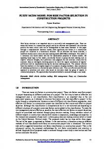
Project Introduction Data Centers & Thesis A Data Center is a dedicated room of computer equipment. These computers are stored in racks, and are usually servers, computational workstations, or switches for communications. The heat load of these rooms can be 200kW, hundreds of times that of a human occupied room. The computers require a cool, dry environment for best performance, and therefore require a dedicated environmental conditioning system. This system often uses as much as 40% of the power to the room just for HVAC. As the cost reaches millions of dollars per year, efficiency is of utmost concern.
[Fig 1.1] - Down-flow Data Center cooling configuration The illustration in Figure 1 depicts a typical Data Center cooling configuration, called down-flow. Here cold air (blue arrows) from the CRAC units (white units) is blown over the servers (black towers) through perforated tiles from a plenum under the raised floor. This hot air (red arrows) is drawn back into the CRAC units for conditioning. Up-flow is the same configuration flipped vertically, with the plenum flowing cold air located in the ceiling.
12/14/2004
11
The CRAC units can either cool the air directly, with an internal cooling circuit, or for very large heat loads employ external cooling circuits. These external circuits employ a refrigerant loop, with the condenser located outside of the building. The goal of Nathan's research is to develop robust Data Center layouts using experimentally validated compact models and design configuration schemes. The first stage of this research is to establish a test facility to validate the computational models that will then be used during optimization. To fit in this project with ME6101, the selection method process proposed in our group Q4S will be tested by selecting the most suitable HVAC equipment for the test Data Center. This project will therefore involve two parts; the researching of selection methods and development of a standardized selection process, and the application of this method to researched HVAC equipment and requirements for use in the experimental Data Center facility.
12/14/2004
12
Project Goals Group Q4S The purpose of this project is to help us determine, for our specific problem of the Data Center HVAC, what the most applicable selection methods are. As with the clarification of task, conceptual design, embodiment, or detail design, there must be a process flow, or template that can be followed to make sure the user is using the appropriate selection criteria. In addition, by standardizing the selection process in such a way, it becomes easier to track and manage decisions over a geographically disperse company. There is a template that thus limits location specific variations in how things are done. With this goal in mind we established the following group Q4S: How can the P&B method be augmented to better address selection utilizing a systematic procedure enabling the selection of the most appropriate decision method for the task? Thus making all assumptions and preferences explicit to facilitate better communication and design in the distributed environment of 2020. We are going to apply things learned from this project into our individual Q4S’s rather than streamlining our individual Q4S into a group vision. This is addressed below relating each members individual Q4S to the group Q4S. Nate’s Relation to Personal Q4S Selection occurs throughout the Pahl and Beitz systematic method, but is not addressed directly in a systematic manner. The group Q4S is a subset of my personal Q4S; both address the customization of the design process to suit the needs of the user. Standardization and the systematic manner make the method proposed in the group Q4S beneficial to geographically dispersed design teams, as group operating differences will be removed enabling communication and understanding. Through answering the group Q4S I will have answered a large part of my individual Q4S, addressing the selection module of my augmented Pahl and Beitz process. Ashley’s Relation to Personal Q4S One of the greatest factors affecting the effectiveness of communicating ideas and information over great distances, and between differing social, economic and business cultures is the differing methods used to arrive at a project direction. There are many internal biases that effect how a decision are made, when you add in the disperse network of divisions and facility groups that will be prominent in the future, the problem becomes compounded. By setting a standard method, you are able to simplify the design process, and facilitate smoother communication of ideas.
12/14/2004
13
Matthieu’s Relation to Personal Q4S Selection would be achieved by someone throughout his life. The process of selection lays on the choice between several alternatives that can seem more or less valuable depending of the point of view of the person. Though this project we will show how we can set up a standardized process to make a good choice in front of a problem. Realization of Group Q4S Through Data Centers HVAC Selection We will utilize the systematic selection process developed to answer the group Q4S in order to select HVAC equipment for the Data Center. The selection will be the physical realization and test of our proposed process, creating a task specific selection process employing appropriate selection methods.
12/14/2004
14
Group Vision of 2020 We completed an affinity diagram of our individual 2020 visions, then collaborated to form the six major categories, and developed this key short list for the project. These are the, per our group vision, standard issues that must be addressed for the year 2020.
R&D
People
Manufacturing
Information
Geographically Dispersed Resources
Marketing
Resources
[Fig 1.2] - Vision of 2020 Spoke & Wheel Diagram From these subsections we have addressed the following key issues: ♦ ♦ ♦ ♦ ♦ ♦ ♦
Standardized & Modular components for multi-location manufacturing Multi-purpose manufacturing processes Information mass accumulation & sharing Local/Wide Area Network to Global Area Network Real Time virtual conferencing Central server based project & version control Globally personalized marketing & advertising
Manufacturing With manufacturing, there will need to be a standardization and modularization of component parts, machine parts and production facilities. Every physical aspect of manufacturing should be location independent; and every process step should be standardized. This will allow processes and people to become interchangeable. Standardizing selection processes become important for this system during the design of the manufacturing process. The strengths of standardized and modular manufacturing components are dispelled if the process for selecting the appropriate units can cause nonuniformity plant layouts and operations. Information Information must be readily available to anyone on the project, in real time. This requires the use of customized data pools, and specialized global networking. This will be
12/14/2004
15
must for keeping in constant contact with a dispersed work force. This will facilitate swifter and easier communication of ideas, thus allowing for disperse groups to base decisions on a global/company wide set of requirements. Versioning control will also become much more important, as you’ll have people in different time zones working on the same task at different times of the day. This will allow for cleaner task and project handoffs, as well as almost 24 hour “working” shift. By standardizing the selection process it is understood what data is available and what research needs to be completed in order to make a decision. This information rich future limits the possibility of incomplete data gathering. The mass availability of information combined with a systematic selection process enables users to apply more rigorous selection methods. Marketing Marketing needs to be handled at a global scale. No longer will items have country, or nationality specific markets. This isn’t to say that individuality will be a thing of the past, but base product needs will probably become more global as far as food, transportation, basic clothing and the like. Marketing will also advance on a personal scale, through mass customized advertising. Global access to records of activities and purchases, similar to the history and cookies features on web browsers, will allow for individual advertisements directed to individuals based on their previous records. Decisions in marketing will become more important as product life cycles will shorten, and consumer fickleness and expectations will increase. This will facilitate the need for a standardized and quicker means for making product decisions. People The rise of mass communication will continue to contribute to the homogenization of cultures around the world. As groups become less isolated, they become influenced by the ideas of other cultures. Many people will become multi-lingual, speaking languages most encountered in their global workplace. For people to be effective members of a group, they must be part of as many aspects of the overall design process as possible. To that effect, meetings must also become “virtual”. This will limit the unintentional exclusion of certain internal, or external divisions due to distance, or time constraints. Also, the information itself should be understandable by any person in any nation that is required to work on the project (diagrams vs. text). Selection is an important part of this information that must be communicated between dispersed group members. In order for all members to understand the reasoning behind the selection, a systematic standardized process must be followed.
12/14/2004
16
Resources No longer will company resources be departmentalized. Teams and groups will be required to make faster decisions with the understanding that the footprint of effect will have a larger scale, not only affecting neighboring departments but also international divisions. Thus the networking of the future will need to be done on a global scale, through true wireless (satellite based) transmission. This will be a must for keeping in constant contact with a dispersed work group. In addition, physical resources, those substances that make up the components used in production, must become interchangeable. This will allow processes to become location independent. Research & Development The impacts of a standardized selection process on research and development will be similar to those outlined above, particularly marketing, as development life cycle will be shorter. Because research and development encompasses most of the above points, it is not necessary to readdress here.
12/14/2004
17
PEI Diagram & Plan of Action The PEI diagram is a useful tool in which phases events and information are pictured. This diagram enables us to understand how the information generate all along the project could lead to the execution of the P&B various phases. It’s a natural way of analyzing because this diagram can both represent the contain of each step of the P&B process and how the information can be used to gradually progress in the P&B design method. Meanwhile, it is also important that all these information stay close to our project goals, the representation of the year 2020 and Q4S of each member. That’s why we have first to collect the 2020 world of each member to build the general view of the team regarding the P&B method and the way this one could be augment. Then, it will be possible to generate the group Q4S: How can the P&B method be augmented to better address selection utilizing a systematic procedure enabling the selection of the most appropriate decision method for the task? Thus making all assumptions and preferences explicit sto facilitate better communication and design in the distributed environment of 2020. Thorough these weeks we must continuously tie the project Q4S to our personal Q4S and learning essays. This project is the concrete realization of the personalization and augmentation of the P&B method by using the different steps of it.
12/14/2004
18
[Fig 1.3] - Project PEI Diagram
12/14/2004
19
Clarification of Task ♦ Daily/weekly meetings scheduled depending of the need. This is the first step to get a precise idea of all the issues of the Data Center project. ♦ Meeting with Dr. Joshi and Dr. Mistree to focus on the crux o the problem concerning both the implementation of the HVAC and the P&B augmentation and personalization method ♦ Analyze of the different issues concerning the implementation of the HVAC trough the reading of the documents given by our two sponsors. This, constitute an analysis of the product and the market at small-scale. ♦ Collection and organization of all the information concerning the HVAC and the Data Center to generate a requirement list. All the wishes and demands are pictured, so that the document would be used to pick and appreciate a potential solution. ♦ Generation of a requirement list concerning the selection method. This document is the start to a deep analysis of the different selection methods and to understand how these could be developed and applied thorough the P&B design process to get the most adapted solution to a problem. ♦ Definition of the schedule and plans with all the deadlines, meetings and resources. Conceptual Design ♦ Application and representation of the requirement list concerning the choice of the HVAC through a selection method. ♦ The process of selection will rely on the expression of wishes and demands primarily listed. ♦ Potential solution must be evaluated: to be a solution of a problem will depend on the ability to suit to the function needs. ♦ The application of the selection method is a way to determine whether or not the process could be adapted and standardized to a more general design case. ♦ We have to measure the efficiency and the impact of the selection process regarding both its requirement list and the requirement list of the HVAC. Embodiment Design ♦ This phase will be oriented in the direction of the HVAC concern in order to implement it into the Data Center. ♦ Quantitative analysis of the solution chosen, product data will be dealt with. ♦ After validation of the selection process, a complete definition of the method will be needed to reach the standardization feature specified in our group Q4S. Detail Design ♦ Implementation details will be emphasized to complete the design process and the process of selection. ♦ Expression of the very last Dr. Joshi and Dr. Mistree requirements and concerns.
12/14/2004
20
Section 2: Research of Selection Methods Why Selection is Important Most Important phase of design The quality of a design depends very heavily on the quality of decisions made in choosing one idea or another. In the past decisions were made in an ad-hoc or empirical basis, as there were no principles or axioms which could be used as absolute foundations. [7] We believe that the quote above by Nam Suh embodies the principle of this project excellently. Decisions occur throughout the design process, each decision closing an area of the design space, and making the design more concrete as the process moves towards the final solution. The final outcome of the design is therefore heavily dependant upon the quality of decisions made during the design process. However, the Pahl and Beitz systematic design method currently does not address selection formally or systematically, although the method calls for selection at many steps in the design process. Selection is often required at the phase gates, the end of the iteration loop, and it is here vital decisions such as go/no-go or the selection of the most promising concept is chosen. If the four phase design process is highly defined, down to details on each step, the selection process also requires a rigorous and defined method. Without a defined process for selection, the foundation of the Pahl and Beitz method is weak, based on an undefined ad hoc system. We crafted our group Q4S in order to address this specific issue. Incorrect Decisions In engineering design, when bad design decisions occur, the culprit most often blamed is the poor state of information that the designer held at the time of the decision: “My data were bad.” However, a key assertion of this paper is that faulty decision methods are also likely causes of bad engineering design decisions. [4] Our group takes a stand that is a less extreme criticism of currently employed selection methods. However, we agree with the fundamental statement that incorrect decisions are often immediately blamed on data without consideration of the applicability of the method that was used. We believe if a decision method gives inadequate answers it is because that particular implementation of that method was flawed. Hazelrigg later agrees with this position later in his paper, when he demonstrates his matrix of selection methods and their applicability, how each method addresses his requirements for selection methods. 12/14/2004
21
One of the biggest flaws in the use of selection methods is in the arbitrary assignment of weighting and numbers to alternatives, and the arbitrary aggregation of results. These practices yield undesirable results, but were cause by the improper use of a selection method, not necessarily a fundamental flaw in the method (although this could also be true). …any method that fails in a simple case has even more opportunity for failure in a complex case and, with a faulty method, failure in the complex case is practically assured. The reality is that complex engineering examples simply hide selection failures in their complexity…[4] The reason that little work exists looking critically at decision methods is the mask of complexity. The complexity of engineering design selection problems, such as the number of variables in each variant comparison, hide the real problem of the method implementation, leading the engineers to believe that either selection methods simply are not applicable to their problems, or that their specific problem is flawed. This thinking compounds the problem, because it generates a lack of interest in the study of decision theory and its applicability to engineering design. Even if a design engineer attempts to determine the most appropriate method of selection for their individual situation, another problem arises. Because of the huge number of techniques available, an analyst can get confused in determining which technique to employ when confronted with a problem. This ambiguity can lead to inappropriate selection, resulting in a misleading solution and incorrect conclusions. This position is taken by the authors of [6], and they were some of the first to realize the importance of providing a structure to guide the decision maker to their appropriate method, depending upon criteria about the decision maker, problem, method, and solution. Our team believes that although we cannot solve the problem of flawed decision making methods, a system for the correct application of methods is a step in the right direction. Inappropriate selection, whatever the cause, is an irreversible waste of resources. These resources can consist of time, money, materials, and energy. It also discourages other designers from employing selection techniques, methods we are trying to defend as valuable. It is therefore imperative that study of improving both selection methods and the application of these methods be undertaken, to avoid loss of both resources and support for the field. Finding Focus “Would you tell me, please, which way I ought to walk from here?” “That depends a good deal on where you want to get to,” said the Cat. “I don’t care much where ______” said Alice. “Then it doesn’t matter which way you walk,” said the Cat. “______ so long as I get somewhere,” Alice added as an explanation. “Oh, you’re sure to do that,” said the Cat, “if you only walk long enough.”
12/14/2004
22
[4] A key part of any design process is the use of decisions to progress to the next step and move forward with the proposed design solution. Selection is used to focus the design, but with the large-scale complex designs of today and in the future of 2020, this task is becoming increasingly difficult. Computers can be used to make selection easier as they can handle large quantities of variables and compute outcomes very quickly. However, computers require a human operator to become a human-computer cyborg, incorporating the human’s tacit knowledge and ability to deal with qualitative data with the computers computational ability. During selection using soft information the lack of information means that computers are of limited use, as it is up to the human to translate their qualitative preferences into quantitative data the computer can process. The difficulties of this process were demonstrated during the selection of conceptual designs of aircraft in ME6101 selection lecture. In these situations if the human’s preferences are inconsistent, it does not matter how efficient or effective the computer algorithm, the results will still be flawed. During selection involving hard information, with quantitative data available, the use of computers is simplified is key decisions are made a priori without depending on exhaustive search. This will make the operation more efficient that relying on using a brute force approach, which is limited in the number of variables it can handle. This variable upper bound is given by Bremmerman’s limit [5], which states the upper limit of any computer system is 270 variables in a factorial design computation, even if the entire earth was made into a computer. It is for these reasons that we cannot simply rely of the power of computers to make selection for us, and must return to decision theory and making the best use of the methods available to us. Defense of a Systematic Method Many of the same arguments given by Pahl and Beitz [1] in their defense of their systematic method are applicable to the defense of a systematic method for selection. The most applicable points taken from p. 70 are: ♦
A deliberate step-by-step procedure ensures that nothing essential has been overlooked or ignored.
♦
If designers are expected to produce better results, then they must be given the extra time a systematic approach dements, though experience has shown that only a little extra time is needed for a stepwise procedure.
♦
Scheduling becomes more accurate if a step-by-step method is followed rigorously
Another advantage of a systematic step by step method is upgradeability. If a method framework already exists it is very easy to incorporate a new method or classification into
12/14/2004
23
the existing framework. This makes the latest developments available to the users easily, instead of them having to research all of this material on their own. The next phase of the project is to address the creation of a systematic method to follow for selection steps of the Pahl and Beitz process.
12/14/2004
24
Tools What tools are in use today? Whether in concurrent engineering or in other multi-actor methods, the development of a product, a process or a service requires a good mastery of the decision process, on one hand, and a good control of information and systems of communication between the actors, on the other hand. In any business, the exchanged and administered information is mostly multiple, diverse, in semantics and multi-dimensional and evolutionary in time. Many actors participate in the definition of the decision processes. These processes are often the place of dysfunctions: they are often not optimized, not formalized and are not involved enough in a progress dynamics. Thus it is important to understand what methods are available, and when to use them, but, in that same vein, it is also important to realize that when selecting a method it is important to understand that the tools that make up the method are unimportant. What’s important is which method will solve the problem we are dealing with. Included in Table 2.1 below are lists of MADM and MODM methods that are currently in use. Generic stages of the MODS process are depicted in Figure 2.1. Howard (1991) identifies several phases of the process, namely: (1) defining the objectives, (2) choosing the attributes, (3) specifying the alternatives, (4) transforming the attribute scales into commensurable units, (5) assigning weights to the attributes which reflect their relative value to the decision maker, (6) selecting and applying an algorithm for ranking the alternatives, and (7) choosing an alternative. In practice this process is highly iterative. For example, the Australian Resource Assessment Commission’s guide on MODS (Resource Assessment Commission 1992) reverses stages two and three. Often a decision maker finds it difficult to identify and weight objectives without first becoming closely acquainted with the alternatives. Feedback exists between the generation of objectives, weighting of objectives and identification of alternatives.
[Fig 2.1] - Generic MODM process. Feedback loops exist between the first two stages.
12/14/2004
25
The MADM processes follow a very similar path, with attributes rather than end objectives being the primary focus.
[Fig 2.2] - Schematic representation of a generic MADM process. Modified from Keeney (1982)
12/14/2004
26
[Table 2.1] - MADM and MODM processes Category Mono-criterion Methods
Method
Description
Cost Benefit Analysis Direct Notation Method Delphi Method
A technique designed to determine the feasibility of a project or plan by quantifying its costs and benefits. Method used in mechanical design and is based on the expertise of the committee who has the responsibility of making the decision. The Delphi Method is based on a structured process for collecting and distilling knowledge from a group of experts by means of a series of questionnaires interspersed with controlled opinion feedback These methods consist in successively comparing the relative importance of the element i with the element j in calculating the ratio c[ij] = p[I]/p[j]. These comparisons are then put in a square matrix, at which time a weight vector is utilized to determine which element is most important.
Pairwise Comparisons Methods
MADM (No Information) MADM (Standard Levels) MADM (Weight Assignment)
MADM (Weight Given Beforehand)
Dominance Maximin Maximax Conjunctive
Disjunctive Direct Assignment Least Square Eigenvector Entropy MITA Lexicographic Simple Weighting TOPSIS Linear Assignment Relative Position Estimation ELECTRE AHP
Considers that each alternative is acceptable as long as the corresponding attributes meet the minimum cutoffs. This method evaluates an alternative on its best attribute regardless of all other attributes The method involves the solution of a set of simultaneous linear algebraic equations and is conceptually easy to understand. Simultaneously involves all participating alternatives to find their respective performances for all criteria in relation to each other With the lexicographic method, the objective functions are arranged in order of importance. Then optimization problems are solved one at a time to determine the “best” decision The Technique for Order Preference by Similarity to Ideal Solution: It is a method with appeals as simplicity (easy to apply) and hypotheses based approach of a problem (the best and the worst situations).
Elimination and Choice Translating Reality) only provide the sorting of the alternatives (in this case, a dominance principles based ranking).
Analytic Hierarchy Process: enables a systematic approach for gathering and quantifying weights and ratings of both objective and subjective criteria in order to compare them on a common scale… A problem is decomposed into a hierarchy where the alternatives are at the lowest level. This technique applies the decomposition, the comparative judgments on comparative elements and measures of relative importance through pairwise comparison matrices, which are recombined into an overall rating of alternatives.
LIMAP
12/14/2004
27
MADM (Weight to be generated) MADM (Local Utility Function) MADM (Implicit Utility Function) MODM (Efficiency solution generation)
UTA
This is an implementation of MAVT where individual value functions (for each criterion) are obtained using ordinal regression.
ILUTA
Pairwise comparisons of some alternative choices
EDMCM
Pairwise comparisons with some trade-off questions.
Implicit Trade-Off
In this method the decision maker specifies a trade-off among the multiple objectives. This method is also known as the e -constraint or the reduced feasible space method because the technique involves search in a progressively reduced criterion space. The original problem is converted to a new problem in which one objective is minimized subject to N – 1 constraints that limit the values of the remaining objectives and the original constraints.
MODM (A Priori Articulation of Preference Information)
Ordinal
In an ordinal ranking, no information is available regarding the magnitude of the differences between the ranked items. All that is known is that A is preferred to B, B is preferred to C and so forth. Various techniques are available for converting data from an ordinal to cardinal scale. They are based on identifying quantitative weights
Cardinal
The cardinal approach is followed when the different objectives have different types, units or scales. Two stages are required to transform these objectives into a set of comparable scales. First, the qualitative terms are transferred into an interval scale. The decision makers should agree on the scaling procedure they use. Secondly, the values with different units are normalized.
MODM (Iteractive – Progressive Articulation)
Implicit Trade-Offs Explicit Trade-Offs
In addition to these methods are those collected, or categorized, and documented by Hazelrigg: [Table 2.2] - Hazelrigg Methods Method Category Description Weighted Sum of Attributes Highly restrictive utility form demands utility independence of attributes, which is rare, and demands that utility be proportional to a measure of each attribute, thus, cannot reflect preferences of the designer. Does not account for risk and uncertainty, thus does not account for value of information. Can be validated only in rare circumstances to which it applies. Fails to distinguish between alternatives of varying risk. Analytical Hierarchy Process Highly restrictive utility form demands utility independence of attributes and other problems similar to Note 1. Formulation allows violation of Property 5 (Barzilai, 1998b). Physical Programming Allows outcomes to dictate the formulation of preferences; assumes linear independence of attributes. 12/14/2004
28
Pugh Matrix
Seeks to construct a ranking matrix using a method that is invalid, and it makes the invalid assumption that a desirable design is comprised of design elements that are selected optimally but independently.
Quality Function Deployment
Fails to recognize that customer preferences cannot be determined correctly in the absence of a specific design decision, and there are particular problems when those preferences are intransitive (Hazelrigg, 1996). It imposes the preferences of the customers (incorrectly determined) on the designer. Does not account for uncertainty and risk. Considers only variability in manufacture and materials, does not include other sources of uncertainty, imposes Taguchi’s preference system on designer.
Taguchi Loss Function Suh’s Axiomatic Design
Suh’s “axioms” are not axioms in the mathematical sense, but instead comprise a preference system, which Suh suggests imposing on the designer. Further the method assumes functional requirements are given, which comprises a constraint imposed on the designer.
Six Sigma
Six Sigma focuses on defects and their prevention. It does not deal with preferences beyond this.
In addition to the above-mentioned tools are those that fall into the category of Decision Based Design. These include the Decision Support Problems, the formulation and solution of which provide a means for making the following types of decisions: 1. Selection: The indication of a preference, based on multiple attributes, for one among several feasible alternatives. 2. Compromise: The improvement of a feasible alternative through modification 3. Coupled or Hierarchical: Decisions that are linked – Selection/Selection, Selection/Compromise, and Compromise/Compromise. All decisions made are done so based on analysis-based information “hard data”, insightbased “soft” information, or both. What tools will be required in the future? New analytic methods enabled by the capabilities of modern computers may radically transform human ability to reason systematically about the long-term future. This opportunity may be fortunate, because our world confronts rapid and potentially profound transitions driven by social, economic, environmental, and technological change. Intentionally or not, actions taken today will influence global economic development, the world’s trading system, environmental protection, the spread of epidemics, the fight against terrorism, and the handling of new biological and genetic technologies. These actions may have far-reaching effects on whether the year 2020 offers peace and prosperity or crisis and collapse. In many areas of human endeavor, it would be derelict to make important decisions without a systematic analysis of available options. Powerful analytic tools now exist to help assess risks and improve decision making in business, government, and private life, and even more advance tools will be available in the future.
12/14/2004
29
Common mistakes when making crucial decisions, like those in Table 2.3, are primary factors in the need to better understand the decision making process, and better define it for the purposes of design. [Fig 2.3] - Common mistakes when making crucial decisions Mistakes
Description
Plunging in
Gathering information and reaching conclusions without thinking about the crux of the issue or how decisions like this one should be made Setting out to solve the wrong problem because your framework causes you to overlook attractive options or lose sight of important objectives Failing to define the problem in more ways than one, or being unduly influenced by the frames of others Failing to collect key factual information because of overconfidence in your assumptions and opinions Relying on ‘rules of thumb’ for crucial decisions, or on the most readily available information Trying to keep straight in your head all the information relating to the decision rather than relying on a systematic procedure Assuming that a group of smart people will automatically make a good decision even without a good decision process Failing to learn from evidence of past outcomes either because you are protecting your ego or because you are tricked by hindsight Assuming that experience will make lessons available automatically Failing to create an organized approach to understanding your own decision process
Frame blindness Lack of frame control Overconfidence in your judgment Shortsighted shortcuts Shooting from the hip Group failure Fooling yourself about group feedback Not keeping track Failure to audit your decision process
12/14/2004
30
Research Selection method is a wide subject that has been many times dealt with. All around the world some people have had to face a problem when carrying out their studies: How could they make the right decisions? Are their criteria relevant? Should they grade them? In the following paragraphs we will try to understand how far people have been to select, create or interpret a good selection method. We will see that studies are various, that they always personalize the problem and bring their own feelings in term of classification. However, a selection method is not only supposed to be accurate, it is also supposed to adapt too many case of study, to be efficient and to be adaptable. Hence, we will see that it could be useful to deal with many scientific areas such as aerospace; biology, computer science or environment. By describing these methods, we want to show that the prospects are huge in term of designing. P&B could be the very first designing process to integrate a brand-new method of selection. But we want also to show that selection methods will never stop to evolve, each year, a number of methods arise with new concepts that are said to revolutionize this field. The following paragraphs is an introduction to these concepts, the purpose is not to point the right or the wrong way to do, but only to show that diversity and modularity are features of selection methods. Methods Structure of a method Selection method is a process that implies many characteristics. It can be summarized as a box where inputs can be: a formulated problem, a list of criteria, and a list of alternative solutions. The output would be the solution found to be the best. The scheme is simple and can be represented as follow [Fig 2.4]:
12/14/2004
31
Alternatives
Problem Actions
Selection Method
Solution
Criteria
Decision Maker (DM)
[Fig 2.4] – Selection method structure The selection method arises from a set of concepts, these concepts must be analysed considering a set of criteria, and these criteria are also ranked among themselves. Finally, the concepts would be ranked based on multiple criteria and their relative importance. A selection method can be viewed as an indication of preference based on multiple attributes, for one among several feasible alternatives; it is also a compromise as it improves a feasible alternative through modification. Features Before using a selection method, designers are meant to classify problems. Hence, they can know whether or not the selection method they were thinking of could be used. However, problems are various and classify them could be an intricate work. Before dealing with a selection method, we must nail down the entire problem, this is not a waste of time and by acting like that we would be likely to choose a pertinent method that can suit with the problem. The set of actions is what designers are likely to do to answer to the problem. A set of actions could be a continuous set of actions or a finite moderate size set of discrete actions. The set of criteria are what designers think to be important to realize or to be respected by the product. Criteria can derivate from a requirement list and cover various fields.
12/14/2004
32
They could be mathematical, quantitative or qualitative. Their importance could be gradually revealed during the study or immediately given , they could be ordered between each other, they could be assigned a weight on each of them or they could be put a function that quantify the preference from an action to another. Criteria can be numerous depending on the complexity of the problem: the more requirements and limitations there are, the more criteria are likely to be sorted and ranked following their importance. Some criteria could hence be considered as mandatory, nonmandatory, dependant to the technique of the problem or non-dependant so that the criteria would be evaluated independently for every new problem encountered. A selection method is dependant of the features of the problem, that is to say whether or not we know the capability and the limitations of the method or the method would give designers a strong or a weak solution. Would the result be consistent? What about the robustness of the method regarding parameters alteration? Is the method easy to use? What time is required to get a solution? What time is required to implement the method? The decision maker (DM) is also really important during the selection process; he can be the designer, an expert or somebody else. When asking several people to solve a problem or to choose what they are thinking to be right to do, we often realize that they would use completely different approach for solving the problem. Why? Maybe because what someone thinks to be really important could be considered secondary by someone else. Objectivity and subjectivity are the crux of the problem when choosing a solution to a problem. Even mathematical problem could be found out by using several different methods. The purpose is then to choose the most effective one, the less expensive and the easiest way to be carried out and implemented. Of course, DM’s are also likely to be influenced by the fact that they should work in groups or individually (e.g. the designing of the strongest and the highest paper house in class), they could also be affected by the amount of work needed and the amount of work they can produce, the amount of time needed or available to produce an appropriate solution and the level of understanding of the decision making process that is used (need more or less background).
12/14/2004
33
Tackle the problem : • • •
D e c i s i o n
M a k e r
( D M )
• •
Mathematical or decision analysis form Can be quantified or qualified Varies upon the size of the number of data, objectives, alternative systems… The nature of the variables: integer or continuous …
Set of Action : • Order the actions • Selection of the “good action(s)” • Arrange the actions in predefined classes • Analyze the consequences of each actions • …
Set of Criteria : • • • • • • •
Mathematical, Quantitative or qualitative. Gradually or immediately revealed Ordered Weight assigned Mandatory Dependency
Selection of the method: • Consistency • Robustness • Ease of use • Time required • Implementation of the method • …
[Fig 2.5] – Selection method flowchart
12/14/2004
34
Different approaches The DSP: a step by step approach: DSP involves a hierarchical decision-making and a set of interactions between these decisions. Decision could be taken sequentially or concurrently. Basically, what could happen is a Preselection process that is in charge of selecting the “most likely to succeed” concepts for further development into feasible alternatives. The steps would be successively: a description of the concepts chosen and their generalized criterion, a datum as a zero standard and compare the concepts, finally, each concept would be assigned a “normalized score” to evaluate its merit. The DSP method includes also the interactions between generalized criteria and is likely to give the most-likely-to-succeed concepts. The selection DSP facilitates the ranking of alternatives based on multiple attributes of varying importance. The order indicates not only the rank, but also by how much one alternative is preferred to another (the weighting is important, and must have a logical backing). In the selection based DSP both science-based objective information and experience based subjective information can be used. One feature that is introduce by the DSP method is the sensitivity to changes in the attribute importance is important, especially with alternatives that score close together on the scales provided. Sensitivity analysis is required to determine the effect on the solution of small changes in the values of the relative importance and also to changes in the attribute ratings. The DSP based only on selection facilitates the ranking of multiple sets of alternatives based on multiple attributes, some of which are coupled between attributes. It arises whenever you have a system that can be decomposed into several inter-dependant subsystems that have to be selected by the designers. The Multi-Criterion-Decision-Making (MCDM) approach: MCDM (Multi-Criterion Decision-Making) techniques break up the deciding factors into 4 characteristics, related to the problem, Decision Maker (DM), the technique, and the solution. The selection of criteria is also different from what it is generally supposed to be: 1. 2. 3. 4.
The characteristics of the decision maker (DM) or analyst involved The characteristics of the algorithm for solution The characteristics of the problem under consideration The nature of the obtainable satisfying solution
It is important to keep in mind that too many criteria mean that there may not be enough information readily available to fulfill them, and more work is required for the selection. An idea might be to break up the levels of criterion available, for faster simpler selection use less, and for a complex problem that is important, take more time using more criteria.
12/14/2004
35
Each of these criteria is then weighted based on the DM’s view of how important it is. An important note is that all the scores and weighting of these criteria will be based on the DM’s level of experience with each technique, as well as anything they research on the subject. The Multi-Criterion Decision-Making DM related Characteristics ♦ ♦ ♦ ♦ ♦
DM’s level of knowledge DM’s desire to interface Time available DM’s actual knowledge Analysts skill
Technique related Characteristics ♦ ♦ ♦ ♦ ♦ ♦
Problem related Characteristics ♦ ♦ ♦ ♦ ♦ ♦ ♦
CPU time required Number of parameters required Ease of use Computational burden Ability to get effective points Ease of coding
Solution related Characteristics
The nature of the solution may be described by its Handling of qualitative data uniqueness, reliability, and efficiency, among Finite number of alternatives (~ selection) others. Non-linear problems Problem size ♦ Consistency of results Infinite number of alternatives (~ compromise) ♦ Robustness of results Dynamic problem ♦ Usefulness of results of DM Handling of integer (quantitative) data ♦ Confidence of results ♦ Strength of effective solution ♦ Number of solutions in each alternative [Fig 2.6] – MCDM Characteristics Before deciding on the appropriate method, a sensitivity analysis is required. This is done as explained in class lecture, by varying the different constants used to carry out the selection procedure. A computer would be good for this process, as it is both very important and time consuming, as the matrices must be re-computed with different weightings. Because the choices will not change, the DM does not have to be directly involved in anything except setting the algorithm up, making use of a computer ideal. Analyzing the final results for all four criterions for much sensitivity will give the final ranking of MCDM methods for that problem. In general however, the MCDM rankings are fairly robust, and order is not changed much during the sensitivity analysis
12/14/2004
36
Hazelriggs Axioms and approach for a good selection method [4] 1. The method should provide a rank ordering of candidate designs. 2. The method should not impose preferences on the designer, that is, the alternatives should be ranked in accordance with the preferences of the designer. 3. The method should permit the comparison of design alternatives under conditions of uncertainty and with risky outcomes, including variability in manufacture, materials, etc., which pervade all of engineering design 4. The method should be independent of the discipline of engineering and manufacture for the product or system in question 5. If the method recommends design alternative A when compared to the set of alternatives S={B, C, D, ...}, then it should also recommend A when compared to any reduced set SR, such as {C, D, ...} or {B, D, ...} or {D, ...}, etc. 6. The method should make the same recommendation regardless of the order in which the design alternatives are considered 7. The method itself should not impose constraints on the design or the design process. 8. The method should be such that the addition of a new design alternative should not make existing alternatives appear less favorable. 9. The method should be such that obtaining clairvoyance on any uncertainty with respect to any alternative must not make the decision situation less attractive (information is always beneficial). 10. The method should be self-consistent and logical, that is, it should not contradict itself and it should make maximum use of available information for design alternative selection.
12/14/2004
37
DSP: Preselection Process
Tackle the problem : • • • • •
Mathematical or decision analysis form Can be quantified or qualified Varies upon the size of the number of data, objectives, alternative systems… The nature of the variables: integer or continuous …
D e c i s i o n
M a k e r
( D M )
DSP: Ranking Process
Set of Action : • Order the actions • Selection of the “good action(s)” • Arrange the actions in predefined classes • Analyze the consequences of each actions • …
Set of Criteria : • • • • • • •
Mathematical, Quantitative or qualitative. Gradually or immediately revealed Ordered Weight assigned Mandatory Dependency
Application of weights
Hazelriggs Axioms for a good selection method Selection of the method: • Consistency • Robustness • Ease of use • Time required • Implementation of the method • …
[Fig 2.7] – Augmented selection method flowchart
12/14/2004
38
Critiques Selecting a method is completely subjective process. Decision maker is the key of the selection method so that from a DM to another the system chosen would be different. The solution would be to computerize the process but solutions would be hence different from software to another. All the method that have been described globally present the same aspect; they only present problems from another point of view and it’s hard to say which one is the most effective. For example, axioms could enhance the ease of use, it’s a more mathematical approach, but by doing this, we would loose some flexibility in the process. On the other hand, the MCDM owns a sensitive approach and is computer orientated, but Sensitivity analysis does not provide by how much what items were changed and does not provide limitations of algorithm. All the works tried to introduce us with new concepts and primarily goal was to show us that it could be applied on a bunch of example. But can a method be validated simply by showing it works for a variety of selection? And as we would never consider using a model of a physical system that had not been verified, why should we do the same for selection methods? Robust, accurate selection methods are required for good engineering design; current methods yield inconsistent and wrong results, even with good data. Engineering design will benefit greatly from the incorporation of decision sciences into its decision methods. Trying to point the best method doesn’t always mean to get the most accurate method, sometimes designers are allowed to approximate solutions to certain extend. Hence, the best method could be the one that provide them with the cheapest solution or the fastest method. All the method doesn’t include that consideration in theirs principles, designers would appreciate to notify what are their all requirements in term of time, money and accuracy. We have a mini-paradox here; we need to apply a selection method to selecting selection methods, so how do we know the method we are applying is appropriate. Summary of findings Because of the huge number of techniques available, an analyst can get confused in determining which technique to employ when confronted with a problem. This ambiguity can lead to inappropriate selection, resulting in a misleading solution and incorrect conclusions. This is very important in relation to P&B as the end of the conceptual phase involves selecting the most promising design variants. If this is done poorly, the entire design will proceed down a poor path, resulting in a weak solution. This in turn wastes time, money, resources, and energy.
12/14/2004
39
It is not that easy to determine if a method is appropriate or not, and there has been many debates over this. In some cases, a method that was thought to be inappropriate has been defended as being applicable, and successfully applied and good results have been obtained. It is still worth trying to select the best method though, as it is so important Designing the best method that could work and be the most efficient universally is idealistic. Perfection can‘t be reached but designers can try to shape the problem closely that they could point the most adapted method for their needs. The difficulty for the designers would then be to outline the problem with its criteria and actions. Include such a method in P&B shouldn’t ruin the flexibility and the rapidity of the design process. Introducing a technique with lots of weights and matrix calculation could be too much time consuming and would require a lot’s of skills from the designers so that the process would use its relative ease of use.
12/14/2004
40
Section 3: Group Augmentation of Pahl and Beitz Critical Evaluation of Base P&B Method The Base P&B Method As stated in our group Question for the Semester, the method that we will use as a framework for augmentation is the Pahl & Beitz Systematic Design Method. In this section we will describe this method and identify the key elements utilizing the Pahl & Beitz text [1]. The Pahl & Beitz method of design is organized into four phases: 1. 2. 3. 4.
Planning and Clarifying the Task – Specification of task and requirements Conceptual Design – Specification of principle(s) Embodiment Design – Specification of layout (& construction) Detail Design – Specification of production
The flow of the Pahl & Beitz process is best demonstrated using a flow chart as given in the text in figure 3.3 and shown below in [Fig 3.1]. Decision making steps are required after each phase, to determine the direction of the project and if it should continue.
12/14/2004
41
[Fig 3.1] - The base Pahl and Beitz method flowchart
12/14/2004
42
Planning and Clarifying the Task This phase sets the initial project direction, determining the goals of the project and the requirements. The main steps of this phase are: 1. Analyze the market and the company situation 2. Find and Select Product 3. Formulate a Product Proposal 4. Clarify the task 5. Elaborate a Requirements List “The purpose of clarification of the task is to collect information about the requirements that have to be fulfilled by the product.” [1, p. 67] “The result of this phase is the specification of information in a requirements list.” [1, p. 67] The following are important questions to ask when clarifying the task [1, p. 130-131]. 1. What is the problem really about? 2. What implicit wishes and expectations are involved? 3. Do the specified constraints really exist? 4. What paths are open for development? 5. What objectives is the intended solution expected to satisfy? 6. What properties must it have? 7. What properties must it not have? Conceptual Design This phase determines the principal solution of the design. The main steps of this phase are: 1. Identify essential problems 2. Establish function structures 3. Search for working principles and working structures 4. Combine and Firm up into concept variants 5. Evaluate against technical and economic criteria Completing these steps results in the principal solution. “Conceptual design results in the specification of principle.” [1, p. 67] “It is possible that there will be several principle solution variants.” [1, p. 67] “A lasting and successful solution is more likely to spring from the choice of the most appropriate principles than from exaggerated concentration on technical details.” [1, p. 68] 12/14/2004
43
Embodiment Design The purpose of this phase is to determine the overall layout of a technical system in line with technical and economic criteria. [1, p. 68] The main steps of this phase are: 1. Preliminary Form Design, Material Selection and Calculation 2. Select Best Preliminary Layouts 3. Refine and Improve Layouts 4. Evaluate Against Technical and Economic Criteria Completing these steps results in the preliminary layout. “It is often necessary to produce several preliminary layouts to scale simultaneously or successively in order to obtain more information about the advantages and disadvantages of the different variants.” [1, p. 68] After developing the preliminary layout the next steps are: 1. Eliminate Weak Spots 2. Check for Errors, Disturbing Influences and Minimum Costs 3. Prepare the Preliminary Parts List and Production and Assembly Documents Completing these steps results in the definitive layout. Detail Design The purpose of this phase is to develop the specification of production. [1, p. 69] The main steps of this phase are: 1. Elaborate Detail Drawings and Parts Lists 2. Complete Production, Assembly, Transport and Operation Instructions 3. Check all Documents Completing these steps results in the product documentation and final solution “This is the phase of the design process in which the arrangement, forms, dimensions and surface properties of all the individual parts are finally laid down, the materials specified, production possibilities assessed, costs estimated and all the drawings and other production documents produced.” [1, p. 69] “Difficulties frequently arise from a lack of attention to detail.” [1, p. 69]
12/14/2004
44
Critical Evaluation of Base Method Regardless of context or position within a given design … the importance of decisions in determining the progression of a given design remains paramount. In fact it is by means of decisions that resources are committed and progress is made. It is at decision points that designers converge and interact. Finally, it is through decisions that tacit expert knowledge and designer preferences are incorporated into a given design. Considering the importance of decisions in design in general …, more attention should thus be paid to the means and methods used for making them. [3] Overall we believe the Pahl & Beitz method provides an excellent design process framework. The emphasis on solution neutrality, and the development of function and working structures before embodiment and adding detail is original and effective. However, in order to address my personal Question for the Semester, to enhance the existing method and enable its use in the distributed environment of 2020 changes and augmentations must be made. However, the Pahl and Beitz systematic design method currently does not address selection formally or systematically, although the method calls for selection at many steps in the design process. Selection is often required at the phase gates, the end of the iteration loop, and it is here vital decisions such as go/no-go or the selection of the most promising concept is chosen. If the four phase design process is highly defined, down to details on each step, the selection process also requires a rigorous and defined method. Without a defined process for selection, the foundation of the Pahl and Beitz method is weak, based on an undefined ad hoc system. We crafted our group Q4S in order to address this specific issue. The base Pahl and Beitz method flowchart [1] is shown in Figure 3.2. Selection is required in the clarification of task phase, the conceptual design phase, and the embodiment design phase. The red box highlights indicate decisions made on ‘soft’ qualitative information; the blue box highlights indicate decision made using ‘hard’ quantitative data. This constitutes a problem because the most important decisions are made using the least amount of information. The lack of information compounds the problem of good selection. We will now analyze the Pahl & Beitz method in general and then Phase my Phase to identify what areas need to be changed or added to answer our group Question for the Semester.
12/14/2004
45
[Fig 3.2] – P&B Flowchart, selection steps highlighted
12/14/2004
46
Setting Initial Direction - Clarification of Task The design decisions made at the upstream of engineering practice affect all subsequent outcomes. Fine tuning in later stages of engineering operations often have marginal effects on the total outcome, and cannot certainly negate wrong decisions made in the conceptual stage of design. [7] It is the philosophy of Farrokh Mistree, Nam Suh, and our group that the clarification of task phase, posing the question, is the most important phase of design. Because this phase sets the course for the entire design process, starting in the right direction is crucial. To quote an ancient Chinese manual of war, “What is the point of starting a 1000 mile journey if you start in the wrong direction?” This quote embodies the concept of how important good selection is during the clarification of task phase.
[Fig 3.3] – Clarification of Task The Pahl and Beitz clarification of task phase is shown in Figure 3.3. The third step in the phase is to find and select product ideas. This selection will dictate the development direction for the entire design, the market, and what type of product will be developed. If this selection is done poorly, it does not matter how good a product is developed, if the market entry is inappropriate the product will fail and the company will suffer economically because of it. Often in industry much effort and money is spent towards researching the market situation and polling customers as to their desires and needs. All of this research time and money is wasted if the analysis and selection using this data is poorly executed. This is a principle argument of George Hazelrigg [4], who argues it is the method applicability, not the data that causes poor selection.
12/14/2004
47
Selecting Concepts - Conceptual Design
[Fig 3.4] – Conceptual Design The Pahl and Beitz conceptual design phase is shown in Figure 3.4. Selection is involved in two steps in this phase; combine and firm up into concept variants, and evaluate against technical and economic criteria. The first, combining working principles into concept variants requires the selection of functions to incorporate into the design variant. If this is done poorly, then the evaluation of the variants to find the principal solution will be using inferior design variants, and will result in an inferior solution no matter what is selected. More importantly, the evaluation against technical and economic criteria is the end of the phase, and acts as the phase gate. It is based on this selection and evaluation that it is decided if the project will continue, or if it is terminated. This means that the life of the project is literally in the hands of the selection of the most promising design concept, which is in turn dependent upon the selection and combination of the working principles. This is the most common point for project termination, before the larger expense of embodiment design, involving CAD work, and prototyping and testing the design.
12/14/2004
48
Selecting Layouts - Embodiment Desgin
[Fig 3.5] – Embodiment Design The first half of the Pahl and Beitz embodiment design phase is shown in Figure 3.5. This phase also has two steps that involve selection, the selection of the best preliminary layouts, and evaluation against technical and economic criteria. Selection at this phase is now based on quantitative data, and the designers have more information about the design to use in selection. This allows for the use of more complex and rigorous selection methods in both steps, but this does not necessarily mean a better selection will be made if the method is not used correctly, or is inappropriate for the task. The problem is that the most important decisions have already been made using ad hoc methods and with no structure or guidance, and so in accordance with Suh’s statement, there is little that the design team can do at this stage to negate any poor selections made further upstream in the design process. Now that we had addressed the shortcomings of the base Pahl and Beitz method, we can address how we will augment it to address these in order to answer our Question for the Semester. However, before we can directly augment the Pahl and Beitz method we must form supporting augmentations that enables the utilization of our proposed augmented method.
12/14/2004
49
External Augmentation In augmenting the existing Pahl and Beitz process, by introducing further detail to the “selection” process, it will also be necessary to touch on certain external components of design. These include, but are not necessarily limited to: 1. Ethics 2. Distributed Communication 3. Automation Ethics Ethics in engineering goes beyond the realm of what is demanded of you, or expected of you as a professional, but also falls into the realm of what you should do. There is a standard of care that is expected of engineers, but the idea of ethics goes beyond even that. As an employer, or as a provider of “skills” you have responsibilities to the people you work for (your clients), to the environment, and to the people you work with and under (i.e. your boss, or company owner). Responsibility to Those you’re working for: Well-publicized instances of engineering failures are often cited in engineering education as examples of engineers’ “negligence”. The notorious failures, however, may not be as relevant as those issues that befall typical engineers in everyday life. To that effect, we must define a “standard of Care”, which is to be the hallmark that all engineers must be mindful of. This standard of care represents the line between negligence and unavoidable or non-negligent error. While engineers have a duty to provide their services in a manner consistent with the standards of care of their professions (whether they are Structural, Environmental, or Mechanical Engineers) an engineer’s service need not be perfect. Perfection, regardless of how hard you try, is impossible. This is due mainly to the amount of unknown or uncontrollable factors that are commonplace to most engineering endeavors. This is where standards become important. Engineers must understand not only the benefits gained by a select group for whom the design is intended, but also the adverse effects a choice may have on others that do not benefit, or benefit on a limited bases, from that idea. 1. Before the Challenger tragedy, some of the engineers had argued that the flight should not go forward, but the interests of supervisory management prevailed. 2. The piercing, ear-damaging noise emitted by an ambulance helps speed patients to the hospital but is not good for bystanders. 3. Similarly, the noise of an airplane speeding passengers to a destination can be injurious to people living under the flight path.
12/14/2004
50
The question becomes, where do we draw the line. How do you weight benefit against potential harm? How do we insure that choices are made in a manner that limits potential error? Responsibility to Those you’re Working With, or under: The responsibility we have to those we work with, and under are a bit vaguer. Where do the responsibilities to the individual end and the responsibility to the company as a whole begin? While there is the need to produce for your employer to your utmost, anything you do cannot go against your moral code, or set of standards. This is why a welldocumented and easily accessible set of standards must be made available to all employees. They must understand, above and beyond dress code, and expected work output, what is expected of them, and the types of decisions they’ll be asked to make. In addition, past company decisions should be made available, and should have an easily identifiable pattern. The question of employee retention, education, training, benefits, family balance, vacation and salary are important, but again must be weighed against the financial well being of the company. Communication Communication is a key component of decisions and the methods by which they are made today, and the future brings even more dependence on a strong communication network. With businesses horizontally distributed over differing continents, or even just within the United States, the ability to properly “hand-off” decisions, attributes involved in making decisions, decision based criteria, or just the underlying requirements that make up the need for a decision must be available real time to all groups involved. Automation of Design Systems Another technological development, the many automated functions associated with a new product and the control and development of these systems, will become formalized in the future. Thus deciding upon control systems will become a requirement. Artificial intelligence would fall under this category and the selection of learning parameters; awareness of the surroundings and development protocols must be addressed. We believe that an automated expert system will be not only necessary, but also commonplace in the design environment of the future. These systems can include automated selection decision templates, House of Quality template systems, or simpler templates such as the title block of a CAD schematic. The integration of these systems will allow for quick access to any design tools needed, with only the essential minimum information input from the user. This streamlines the design process further by automating much of the low level processing and calculation work, leaving the design team to work at a higher conceptual level, improving team efficiency considerably. 12/14/2004
51
The focus of our project is upon selection methods, and their implementation. Our method can be integrated into a computer template expert system, and hence become even more streamlined in the future. Another advantage of utilizing a digital computer is the integration of communication abilities. This means that distributed engineers can each fill out their template, and these can be combined to determine the overall selection with respect to all members of the group. This would allow for distributed decisionmaking, which is currently very difficult and time consuming to accomplish. Integrated Software Data Exchange The concept of a worldwide network or WAN was introduced in our design and manufacturing vision of 2020. An important aspect of this that must be addressed is the exchange and interoperability of computer data. Today there is a degree of interoperability, but this is still limited to products of similar nature (text editors or CAD programs). Said systems will need to be improved upon in the future, to limit the effects of “interpretation” in the area of decision making, and selection. Integrated Hardware Communication In order to keep all distributed team members operating at maximum possible efficiency, all hardware must be able to communicate effectively. This again builds off of the World Area Network concept, allowing for any electronic device to be connected to any other in the world. This will require a common communication protocol, similar to Blue Tooth that was developed recently, to allow all PDAs, cellular phones, computers, and digital notebooks to exchange data. This will allow for an engineer on a project to always have access to whatever information they need. Although most work will be done using the digital notebooks or computers, if the engineer in out of the office, they can use their PDA and still retain almost all of their functionality. Information Depots In our envisioned world of 2020 information mass accumulation and sharing will occur. Currently there are many emerging and successfully established sites that deal with the accumulation and sharing of information. This information does not have to be centrally based; rather it could be a complied list of off-site resources, such as the site LexusNexus or other research sites. We also believe that information will be stored both on central servers, such as commercial data warehouses, selling access to their information, along with subscriber or free services that are linked lists of data, operating in a similar fashion to the Napster or Gnutella sharing systems. The Global Area Network enhances the impact of these data warehouses; a satellite based global access system, allowing users to connect in any location. Therefore remote engineers will never be without any data they need, as they will have instant access at all times though their digital notebook, PDA, or mobile phone.
12/14/2004
52
Each of these areas must be addressed in the future in order to allow for easier, more efficient decision making between globally disperse working groups. This is a requirement to limit the potential for liability involved in making incorrect decisions based on poor information sharing, selection criteria’s, or misunderstandings in need.
12/14/2004
53
Clarification of Task Structure of Formalized MCDM Selection Process The structure of our proposed formalized MCDM selection process is based on a similar system to the Pahl and Beitz four phase system. We have therefore followed the four phases for the development of the process, which is outlined below. 1. Define the desired objectives or purposes that the MCDM techniques are to fulfill based on the requirements list for techniques. 2. Select Evaluation criteria that relate technique capabilities to objectives. 3. List and Specify MCDM techniques available for attaining the objective of modeling the multicriterion problem on hand through the use of the method attribute tree diagram. 4. Determine technique capabilities or the levels of performance of a technique with respect to the evaluation criteria be setting up and solving a multicriterion problem. 5. Construct an evaluation matrix (techniques vs criteria array), the elements of which represent the capabilities of alternative techniques in terms of the selected criteria (obtained in step 4). 6. Analyze the merits of the alternative MCDM techniques and select the most satisficing technique. 7. Application of the selected MCDM techique. 8. Verify that selection is indeed representative of the overall goal, and that it meets the established requirements set forth in the project requirements list. 9. Signing of decision by all members involved in process, ascertaining that they accept the responsibility of this decision and the resulting design path that is chosen. Steps 1-5 constitute the problem formulation procedure, while step 6 is the implementation of the MCDM technique selection. Step 7 will not be described in this section, but see the application of the method to the HVAC selection in section 4 of this report for a full example. Steps 8-9 are post selection processes, to check the results against the original goals and to ensure that the responsibility of the decision makers is understood. After this full process has been described we will show how it fits into the Pahl and Beitz Systematic Design method as an augmentation.
12/14/2004
54
Selection Methods Requirements List The formation of a selection methods requirements list is a two-step process. First the desired objectives of the selection must be defined. This is then used to determine the selection of the evaluation criteria used to determine the most applicable selection method. This is a very important step of the process, because is the high level direction for the selection is wrong, it does not matter if the implementation of the rest of the method is perfect, it will still give a meaningless result. Define Desired Objectives for Selection The process begins at the highest level, determining the overall goals of the selection process. This will be dependent upon the stage of the design process in which this method is being applied, or if it is being used as a stand alone tool. The first task of the user is to determine what kind of problem they are faced with. Decisions break down in the following manner: ♦ ♦
“Whether” Decisions “Which” Decisions
Whether decisions do not require any comparison with alternatives, and their outcome does not affect other issues, making them essentially independent. These kind of problems often have a “yes or no” answer to them, and are therefore trivial and not in the scope of this method. Which decisions do involve comparison with alternatives, and are the focus of this project. Which decisions can be sub-divided into selection decisions and compromise decisions, which is discussed in the next section. Once it is determined that the problem is a “Which” decision and that indeed this process is applicable the user must determine what information they have available. This is important because it is used to determine which MCDM methods can be applied to their problem. This information should be written down and stored, formalizing the problem and associated information. This is important because real world problems are in a constant state of flux, and the variables and information are continually changing. This makes selection and applying MCDM methods very difficult. Through formalizing the information and “freezing” it, the proposed process is applicable. Once the formalization of the problem, the writing of the goals of the selection and the information available has been completed, it is time to move to the next step, selecting the evaluation criteria.
12/14/2004
55
Select Evaluation Criteria This is the second most important step after determining the overall high-level goals of the selection. The proper determination of the applicable evaluation criteria has a larger influence on the outcome of this MCDM selection process than any other individual factor. There are a huge number of criteria that a MCDM technique can be judged on, and it is the purpose of this project to help the user select what is appropriate for their specific problem. This selection process is a “Whether” decision, a yes or no choice of whether the criteria listed is applicable to their problem or not. This means that the use of a selection method to select these evaluation criteria is not necessary or applicable. However, these decisions are still entirely subjective and up to the decision maker to justify their preferences. This is important, because if this justification is not documented, there is no way to determine the preferences of the decision maker and following their logic to see if an error in judgment was made. The decision maker is not entirely alone in this selection. They can also look at previous work and applications of this process to determine what criterion they should use. This is described later after each of the evaluation criteria categories has been reviewed. The criteria relating to MCDM methods involves the assumptions made by a method, its information requirements, the decision situation, the solution needed, and the attributes of the people involved making the decision. These different criteria can be sorted into the following four categories: 1. 2. 3. 4.
The characteristics of the decision maker (DM) or analyst involved The characteristics of the algorithm for solution The characteristics of the problem under consideration The nature of the obtainable satisficing solution
These have been abbreviated to: 1. 2. 3. 4.
DM Related Method Related Problem Related Solution Related
Each of these categories has many criteria that can be considered. However, the selection of the most relevant criteria is important, and simply using every criteria in the selection is not the best approach. This is because the more criteria used, the more information is required for the selection. This information was set during the definition of the objectives, and may not be available or will require more time in order to collect. It will also place a higher computational burden on the user of the MCDM selection process. Finally, some criteria is not applicable to specific situations. This is important because
12/14/2004
56
the method employed for the selection is not perfect, and therefore the inclusion of excess criteria can interfere with the results slightly in some cases. Through research of many papers and their references, the following list of criteria was determined, divided into the appropriate categories. This criteria is general, in the same manner as the Pahl and Beitz method. It is up to the user of the process to personalize these criteria to their specific problem. This can also include adding new criteria if there is a pertinent issue that is not covered in this list. DM Related Characteristics The DM or analyst related categories reflect the DM’s level of knowledge, ability, and willingness to utilize the criteria given. The choice of these characteristics is determined by the users previous experience with each MCDM method, as well as any other opinions or previous work they can obtain in order to make judgment. The DM related criteria are unrelated to any of the other characteristics and hence can be evaluated irrespectively of the characteristics of the problem under consideration. Therefore once these characteristics have been selected, weighted, and values determined, they can be used again by that DM without recalculation for any problem. DM’s level of knowledge DM’s desire to interface Time available of DM DM’s actual knowledge Analysts skill DM's acceptance of method's assumptions DM's ability/willingness to provide 7 preference information required by method 1 2 3 4 5 6
8 DM’s preference form Method Related Characteristics The Method related characteristics are also independent of the problem characteristics. Because of the subjective nature of the selection of characteristics and their associated weights and values (discussed later) it is important that each DM or analyst construct their own personal matrix relating MCDM techniques to the Method characteristics. Again because this is problem independent this matrix can be re-used for different future selection problems. 1 2 3 4 5
CPU Time required Implementation Time required Interaction Time required Number of parameters required Ease of use
12/14/2004
57
Computational Burden Ability to get efficient points Ease of coding Ability to handle qualitative criteria Ability to choose among discrete sets of 10 alternatives 6 7 8 9
Ability to choose among continuous sets of 11 alternatives 12 Ability to solve dynamic problems Ability to solve stochastic problems 13 (uncertainty) 14 Comparison with goal point 15 Comparison with aspiration level 16 Direct comparison 17 Strongly efficient solution 18 Complete ranking (ordinal) 19 Cardinal ranking 20 Ability to handle integer variables Decision maker’s level of knowledge 21 required 22 Applicability to case of group decision maker 23 Compensatory (handle tradeoffs) 24 Non-compensatory (cannot handle tradeoffs) Max. Number of alternatives and attributes 25 that can be considered and evaluated 26 Domain independent 27 Type of information elicited Problem Related Characteristics Another aspect to be considered is if a particular MCDM technique can be applied to perform the desired tasks required for the problem under consideration. Selection of applicable criteria in this category is most important, and requires that most understanding and knowledge of the DM. This is strongly linked to the establishment of the goal of the selection, for example does the DM want a complete rank ordering, or only a partial one? These considerations must be made before selecting characteristics. These problem related characteristics are independent of the DM or analyst, and therefore are will remain constant even if the team or person involved with the decision changes. 1 Handle qualitative data 2 Finite number of alternatives 3 Non-linear problem 12/14/2004
58
4 Number of attributes (size of problem) 5 Infinite number of alternatives 6 Dynamic problem 7 Handle integer data 8 Number of objectives 9 Number of systems 10 Number of constraints 11 Number of variables 12 Decision maker’s level of knowledge 13 Time available for interaction 14 Desire for interaction 15 Confidence in original preference structure 16 Plausibility 17 Problem Type 18 Flexibility of statement of problem Solution Related Characteristics The preference of one MCDM technique over another is a function of the results obtained from the use of that technique for the problem under consideration. The nature of the solution is described primarily by its uniqueness, reliability, and efficiency. Given these solution characteristics, the Dm or analyst must also have decent knowledge of the problem under consideration, and the results they are looking for from applying the various MCDM methods. This can be obtained from assessing solutions obtained from past problem applications. If this information is not available, it would be conceivable to apply more than MCDM technique for the purpose of completing an information record for future use so that it would not have to be done again. 1 2 3 4 5 6
Consistency of results Robustness of results DM Confidence in results Strength of efficient solution Number of solutions per alternative Usefulness of results of DM
Independence of Categories As noted in each of the four criteria categories, each category is independent of the others. This independence means that a database of evaluation matrices can be established and stored for re-use, saving time for future applications of this procedure. 1. DM Related – The characteristics of the DM can be established and stored for each member of a team. This complete matrix will be the same for any problem, 12/14/2004
59
and only needs to be updated when the DM feels that they have acquired more skill or experience and will re-evaluate the matrix. 2. Method Related – The characteristics of the method can be stored in a database along with the descriptions and previous applications of the various MCDM methods. This means that the characteristics of the MCDM methods has already been determined and can simply be re-used for future problems. If a new MCDM method is introduced then it must have its characteristics computed and added to the matrix database. 3. Problem Related – These criteria relate to the tasks required of the problem. This matrix will therefore only have to be computed once for the problem, regardless of the changing of team members or the number of people involved in the decision. The re-use of this information is limited as it is specific to the task under consideration. 4. Solution Related – The solution related characteristics should be stored in the database with the method related characteristics as examples of solution characteristics for specific problems. Because these characteristics are partially dependent upon the problem, they cannot directly be re-used without judgment if the problem under consideration is similar to the problem what the matrix was evaluated for. However, examples are used to determine the values of the matrix later, and therefore the results will be useful even if not directly applicable. Justification of Criteria After the DM or team has determined the criteria they will use to evaluate and select the MCDM method for the problem this decision must be justified. This is for the purpose of being able to follow a decision, and understand why the selection occurred as it did. Because this is a subjective process, all preferences should be made explicit. In order to accomplish this our group has proposed the following sign off lists and form shown at the end of Section 3. The completion of this form ensures that all criteria have been considered, gives a brief justification of what was included or not, and a signature establishing the responsibility of the person involved with the decisions.
12/14/2004
60
Phase Checklist Using the same idea as the Pahl and Beitz systematic method, we will employ a phase gate after each section to determine that each step of the process has been completed. Phase Checklist: Clarification of Task 1. 2. 3. 4. 5.
Have all the group, project, market and exterior influences been analyzed? Have high-level selection ideas been discussed, and documented? Has the project task been properly clarified? Have the essential problems been abstracted? Has an elaborate criteria list been documented?
Result = A criteria list “Per the summary criteria posed above, we have completed this phase of work and are now able to move on to the next phase of work.”
12/14/2004
61
Conceptual Design Determine available Techniques It must be understood that the method chosen for making a decision is not just a matter of preference, but can directly affect the outcome — and can give you an entirely different result. So the question becomes, what is the right method? There is no single right method for every situation, but there is a right starting point — the decision you have to make. The choice of a decision method depends on the kind of decision you are trying to make. Most decisions are "whether" decisions or "which" decisions. "Whether" Decisions If you are trying to decide whether to dismiss an employee "for cause", or whether to split the company stock, or whether customers like a new package design for a product, then you have a "whether" decision. "Whether" decisions usually have binary solutions: ♦ ♦ ♦
Yes or no, Up or down, Guilty or innocent.
They are also called non-comparative decisions because the decision does not require comparison with similar issues or situations, and the outcome does not directly affect any other issue. Example: If you dismiss an employee for cause (a "whether" decision), the decision is unaffected by that person's performance compared with other employees, nor does it directly effect any other employee. "Which" Decisions If you are trying to decide which issue is more important, or which person should be promoted, or which skill is the most important to train, then you have a "which" decision. "Which" decisions have multiple outcomes greater than 2. They are also called comparative decisions because each outcome must be compared with all the others to decide "which" one of them is the right choice. Example: If you intend to promote 1 of 3 candidates to an executive position, each candidate must be compared with each of the others, one of whom is promoted, and 2 who are denied promotion, and may choose to leave the company. Within the realm of the “which” decision you have two distinct categories: ♦ ♦
Selection decision: which can be solved with the MADM family of methods, Compromise decision: which can be solved with the MODM family of methods
In the case of the selection problem, one is making a choice between a finite number of alternatives and must choose the most relevant one, while taking into account the diverse
12/14/2004
62
attributes. Solving a compromise problem consists in taking an initial alternative and improving it through modifications. With this understanding, it is possible to steer decision makers, based on the types of situations they find themselves in:
Whether/Mono-criterion
Delphi, direct notation, pairwise comparison methods, cost benefit analysis...
Optimization Methods
Selection
MADM
Compromise
MODM
Which/Multi-criteria Methods and Tools
Other Methods
DSPT, Robust methods, Simulation methods, Cost predictive methods, FMECA, Pareto diagram, Ishikawa diagram, Value analyssi, QFD, Monte-Carlo simulation, Expert system, Fuzzy logic based methods, Statistical based methods....
[Fig 3.6] - Method & Tools Tree Diagram
12/14/2004
63
Breaking out the MADM methods provides: Dominance No Information
Maximin Maximax
MADM Method Usage Tree
Conjunctive Standard levels Disjunctive
Direct assignment Least square
Weight assignment
Pairwise comparison of all attributes
Eigenvector Entropy
Appropriate comparisons of attributes
MITA MADM Lexicographic
Ranking of all attributes
Simple Weighting Definition of ideal and negative ideal points
TOPSIS Weight given beforehand Linear assignment
pairwise comparisons of all attributes
Relative position estimation ELECTRE AHP
pairwise comparisons of all alternatives and attributes
LIMAP
pairwise comparisons and ideal points
Weight given beforehand
Weight to be generated
UTA
Ranking of a subset of alternatives
Local utility function
ILUTA
Pairwise comparisons of some alternatives
Implicit utility function
EDMCM
Pairwise comparisons and trade-off questions
[Fig 3.7] - MADM Tree Diagram
12/14/2004
64
While the MODM methods break out as such: Parametric
MODM Method Usage Tree Epsilon-constraints Efficient solution generation (A posteriori articulation of preference)
Implicit trade-off
Non-inverior set generation
MOLP
Envelop
A priori articulation of preference information
Ordinal
Lexicographic Utility function
MADM
Cardinal
Ideal points
Goal programming
STEM Displaced ideal point Implicit trade-off SEMOPS ISTM Iteractive (Articiulation of preference information made progressively)
Geoffrion Interactive surrogate worth trade-off Explicit trade-off
Interactive goal programming Zionts-Wallennius REISTM
[Fig 3.8] - MODM Tree Diagram
12/14/2004
65
Descriptions of the above mentioned methods can be found in Section 2b. In all of these cases, and many more, finding out whether something is important is less of an issue than identifying which is more important given our current constraints. Only the comparative methods can reliably provide us with the data for difficult comparative decisions. The reality of today's decision making is that we must work harder to ensure that our decisions are reflected in our strategies for data gathering. If we are not clear about the decisions we are trying to make from the data we gather, we will persist in asking inappropriate questions, and assembling them into inappropriate questionnaires. Selection of Appropriate MDCM Methods Following the tree diagrams given above as they branch out will give various applicable MCDM methods for the problem under consideration. This is accomplished through starting at the bottom of the tree, and determining the most appropriate branch to follow at each junction. This may result in a single method, but will most likely lead to a variety of applicable MCDM methods. This is only to be used to narrow the focus of the available MCDM techniques, not determine the method to be used, this has been tried before and found to be inappropriate in work done by MacCrimmon (1973). After the tree diagram has been used to determine the techniques applicable to the problem, the DM must determine if the techniques are applicable by the users. This is another “Whether” decision, and is simply if the suggested method is known and can be applied, is unknown but is worth learning, or would required too much time and resources to be considered. Justification The team or DM does not have to justify their path through the MCDM tree, it is assumed that they can determine the correct path to follow and this process is not subjective, however the selection step does require justification. After the DM or team has determined the MCDM techniques they will consider and select during the MCDM selection process this decision must be justified. This is for the purpose of being able to follow a decision, and understand why the selection occurred as it did. Because this is a subjective process, all preferences should be made explicit. In order to accomplish this our group has proposed the following sign off lists and form shown at the end of Section 3. The completion of this form ensures that all criteria have been considered, gives a brief justification of what was included or not, and a signature establishing the responsibility of the person involved with the decisions.
12/14/2004
66
Construction of Matrices After the selection of the applicable MCDM evaluation criteria and MCDM techniques from the previous two steps, the evaluation matrix can be constructed. However, before this can be completed some more details must be established to aid in the selection process. Weighting of Characteristics Every criterion in each of the four characteristics groups: DM related, method related, problem related, and solution related must be given a weight representative of its relative importance in the group. This weighting cannot be arbitrary, and must be carefully considered based on the DM’s preferences and experiences, combined with evaluation of previous results of this MCDM selection process application. These weightings can use any scale the DM desires so long as it is justified and explained, however we suggest using a 1 to 5 scale as it fits the relative weighting very well. If it is determined that a finer resolution is required or that there is a larger difference of weightings are required we suggest a re-evaluation of the criteria used. This is because if some criteria are not very applicable, they should not be included rather than being given a very low weighting. An example of weighting different criteria for the method related characteristics is “ease of coding” versus “number of parameters required”. We would suggest weighting “ease of coding” much higher than “number of parameters required” because based on our experience it is much more difficult to understand and use a technique that has a complex execution and calculations than one that requires a lot of input data, which is simply more time consuming. Justification After the DM or team has determined the weightings they will apply to each of the characteristics this decision must be justified. This is for the purpose of being able to follow a decision, and understand why the selection occurred as it did. Because this is a subjective process, all preferences should be made explicit. In order to accomplish this our group has proposed the following sign off lists and form shown at the end of Section 3. The completion of this form ensures that all criteria have been considered, gives a brief justification, and a signature establishing the responsibility of the person involved with the decisions.
12/14/2004
67
Evaluate Matrices The evaluation matrices are constructed with the available MCDM selection methods along the top, and the different criteria and weighting along the left edge for each of the four criterion as shown the examples below. DM Evaluation Matrix Alternative MCDM Techniques Criteria DM’s level of knowledge DM’s desire to interface Time available to DM DM’s actual knowledge Analysts Skill
Weight 4
1 4
2 3
3 6
4 5
5 6
6 3
7 4
8 7
9 9
10 5
3
9
9
10
8
5
7
8
9
8
6
3
10
10
8
8
5
3
2
9
9
7
2
9
7
8
10
9
6
5
10
8
7
1
10
9
8
7
6
7
6
4
3
6
The DM or analyst related criteria are meat to reflect the DM’s or analyst’s level of knowledge and willingness to utilize these criteria. Evaluation of each of the matrix cells is made using a subjective scale of 1 to 10 that must be explicitly defined and explained. In the case above, and the system our group suggests, 1 represents the worst case, where that MCDM method does not meet the requirement at all, and 10 the best case, where the best possible performance that can be attributed to the particular technique is obtained. Method Evaluation Matrix Alternative MCDM Techniques Criteria CPU time required
Weight 3
1 6
2 4
3 4
4 7
5 4
6 3
7 8
8 10
9 6
10 7
No. of parameters required Ease of use
2
9
9
7
7
8
7
4
5
7
7
4
8
7
6
8
9
7
9
7
7
8
Computational burden Ability to get effective points
4
6
5
7
7
4
4
9
8
8
7
5
8
9
9
1
8
6
6
4
5
8
Ease of coding
4
8
9
6
7
8
7
9
7
7
6
The method evaluation matrix represents the application of each method in relation to its use by the DM or analyst. Therefore the same scale as used in the DM related characteristics evaluation should be used to the method applicability criteria. Again this is a 1 to 10 scale with the same characteristics, 1 being the worst applicability, and 10 the 12/14/2004
68
best possible performance from a method. Because of the subjective nature of these evaluations, each DM should fill out their own version of this matrix evaluation. This is because each analyst or DM is going to consider the same methods many times and this allows for data re-use as noted previously. Problem Evaluation Matrix Alternative MCDM Techniques Criteria Handle qualitative data Finite No. of alternatives Non-linear problem Problem size
Weight 5
1 1
2 1
3 1
4 0
5 0
6 1
7 1
8 1
9 0
10 1
4
1
1
1
0
0
1
1
1
1
1
3
1
1
1
1
1
0
0
0
0
1
3
1
1
1
1
1
0
0
1
1
1
Infinite No. of alternatives Dynamic problem
4
1
1
1
1
1
1
1
0
1
0
3
1
0
1
0
0
0
0
0
0
0
Handle integer data
2
1
1
1
1
0
1
1
1
0
1
The problem evaluation matrix is supposed to model is a particular technique can be applied to perform certain tasks corresponding to the criteria selected. Evaluation of the applicability of the techniques with respect to the problem related criteria is made using a “yes” or “no” response. This corresponds to a 0 or 1 answer, with 0 meaning no and 1 meaning yes for computational purposes. Different scales between the matrices is acceptable because of the computational aggregation routine employed, described later. As stated previously, these responses are based on the DM and analysis’s experience in applying the techniques as well as previous work done by others. Solution Evaluation Matrix Alternative MCDM Techniques Criteria Consistency of results Robustness of results Usefulness of results to DM Confidence of results Strength of effective solution No. of solutions in each alternative
12/14/2004
Weight 2
1 8
2 6
3 9
4 7
5 8
6 10
7 7
8 4
9 5
10 7
2
8
6
9
7
7
8
7
8
9
6
3
6
7
8
5
6
9
8
8
8
6
3
7
6
8
5
5
3
6
6
5
5
1
7
9
7
2
5
4
3
3
4
5
1
9
5
7
9
7
7
3
3
4
6
69
The solution evaluation matrix determines the preference of one MCDM technique over another as a function of the nature of the solution to be obtained. A subjective scale requiring definition is required again, and it is suggested that the same scale as used in the first two matrices be employed again. However, this time during the evaluation more information is required of the DM about both the methods to be employed and the problem. This is where the previous results from application of methods and their problems stored in the database can be used to aid the DM in the completion of this evaluation matrix. Justification Because completing a justification of every matrix value would be absurd, the only justification required is that of the scale utilized. The yes-no scale of the problem related evaluation matrix does not require justification or definition. If one scale is utilized for the other three matrices as shown above only one scale explanation and justification is required. This is for the purpose of being able to follow a decision, and understand why the selection occurred as it did. Because this is a subjective process, all preferences should be made explicit. In order to accomplish this our group has proposed the following sign off lists and form shown at the end of Section 3. The completion of this form ensures that all criteria have been considered, gives a brief justification, and a signature establishing the responsibility of the person involved with the decisions. Phase Checklist: Conceptual Design 1. Have appropriate MCDM techniques been identified and selected? 2. Have weights justifying the relative importance of selection criteria been applied? 3. Have the four evaluation matrices been evaluated thoroughly? Result = A complete MCDM method evaluation matrix “Per the summary criteria posed above, we have completed this phase of work and are now able to move on to the next phase of work.”
12/14/2004
70
Embodiment Design Analyze and Select the Technique The sequential steps taken during this process to select MCDM processes can be lumped into two stages, problem formulation and problem solution. The previous steps comprise the problem formulation and this step is the problem solution. This is the most technically difficult but least important stage of the process, its computational burden is high but cognitive burden is low. Because the problem of selecting an appropriate MCDM technique itself is a multicriterion problem, the MCDM selection process could theoretically be applied to this problem also. However, this would create a paradoxical cyclical process, and no progress could be made. This does not mean that an arbitrary selection technique should be chosen either though. In the case of selection of MCDM techniques, the problem is fixed, and therefore once an applicable method is found it can always be applied to this selection problem. Through research we have found that the composite programming selection technique is very applicable to this selection problem. Although there are limitations to this technique as discussed by George Hazelrigg in his paper [4], it meets the needs and constraints of our selection problem. The problems Hazelrigg has identified with the programming method are: 3. The method should permit the comparison of design alternatives under conditions of uncertainty and with risky outcomes, including variability in manufacture, materials, etc., which pervade all of engineering design This is not of concern and uncertainty is not in the scope of this project, and currently very few selection methods can cope with uncertainty in decisions. 9. The method should be such that obtaining clairvoyance on any uncertainty with respect to any alternative must not make the decision situation less attractive (information is always beneficial). Again this is dealing with uncertainty. Our selection of information at the beginning of this process freezes the dynamic problem and removes uncertainty for the scope of this method. Although this is an assumption and does not accurately reflect reality, the overall application of this process is still very beneficial. Through the selection of evaluation criteria in the second step this point should be a non issue if done correctly, as only the information required will be used, and any more information should not affect the results if the choice of criteria was performed well.
12/14/2004
71
Applying the Selection Technique There are two steps to this analysis. The first is the solution of each of the four evaluation criterion matrices separately, and the second is the combination of these results into a final solution. An algorithm that fulfills this requirement well is the composite programming MCDM technique proposed by Tecle in 1988 [6]. We have augmented the process for the needs of this project. This algorithm is an extension of compromise programming (Basdossy et al. 1985), and is adapted here to perform the two level tradeoff required. Evaluation of Individual Matrices At this first level, different Lp-norms are applied to seek a compromise within each of the four criterion groups. This produces a ranking of the MCDM techniques under consideration. The Lp-norms, Φk for each of the k (k = 1,…,4) aggregated criterion groups are:
* dik − dijk Ik φk = ∑ i =1α ki * ** dik − dik
[Eq 3.1] – Lp Norm Calculation Where: *
**
dik is the maximum of dijk over alternatives j = 1,…,J and dik is the minimum of dijk .
α ki is the weight associated with criterion i (i = 1,…,Ik) in group k (k = 1,…,4). The overall composite goal function, G for the MCDM technique selection problem can be written as:
G = ∑ k =1 β kφk K
[Eq 3.2] – Lp Norm Aggregation Where:
β k is the average of the weighting functions in each set k
12/14/2004
72
Applying this formula and ranking an example for the DM criterion matrix yields:
Criteria DM’s level of knowledge
Weight 4
1 4
2 3
3 6
4 5
MCDM Methods 5 6 7 8 9 10 11 6 3 4 7 9 5 9
DM’s desire to interface
3
9
9
10
8
5
7
8
9
8
6
Time available to DM
3
10 10
8
8
5
3
2
9
9
DM’s actual knowledge
2
9
7
8
10 9
6
5 10
Analysts Skill
1
10
9
8
7
7
6
1
2
3
4
5
6
6
4
Normalized Results 7 8 9 10
12 2
13 4
14 4
15 9
3
2
5
5
8
7
7
5
6
6
8
8
7
7
4
7
9
7
3
6
6
7
5
8
6
11
12
13
14
15
2.857 3.429 1.714 2.286 1.714 3.429 2.857 1.143 0.000 2.286 0.000 4.000 2.857 2.857 0.000 0.375 0.375 0.000 0.750 1.875 1.125 0.750 0.375 0.750 1.500 2.625 3.000 1.875 1.875 0.750 0.000 0.000 0.750 0.750 1.875 2.625 3.000 0.375 0.375 1.125 1.125 1.875 1.500 1.500 0.750 0.333 1.000 0.667 0.000 0.333 1.333 1.667 0.000 0.667 1.000 1.000 2.000 1.000 0.333 1.000 0.000 0.143 0.286 0.429 0.571 0.429 0.571 0.857 1.000 0.571 0.571 0.429 0.714 0.286 0.571 Value 3.565 4.946 3.417 4.214 6.369 8.940 8.845 2.750 2.792 6.482 5.321 11.304 7.946 6.851 3.071 Rank
5
7
4
6
9
14
13
1
2
10
8
15
12
11
After each of the four individual criteria evaluation matrices has been evaluated the overall function is computed, resulting in an overall rank ordering of all of the MCDM techniques. However this alone is not enough. A sensitivity analysis must also be conducted to determine the stability of the results, and the final results themselves must be questioned to see if they make sense.
12/14/2004
73
3
Sensitivity Analysis For our proposed method we suggest using a sensitivity analysis of adding 5% and 10% to the values of the top method, and then subtracting 5% and 10% and repeating. This will give a general look at the sensitivity of the top selection. However, if there is a specific criterion that has a much higher weighting than the rest, it is worth an investigation of changing the values involving that weighting to determine the effects on the overall ranking obtained at the end. Examples of this sensitivity analysis are shown below. Changing the highest weighting value: 4 Value 3.57 4.941 3.4 4.2 6.35 8.923 8.82 2.715 4.21 6.46 Rank 4 7 3 5 9 14 13 1 6 10 Value 2.85 4.083 2.98 3.63 5.92 8.066 8.11 2.429 4.082 5.89 3 Rank 2 7 3 5 10 13 14 1 6 9 3 4.339 7.03 5 Value 4.28 5.798 3.83 4.77 6.77 9.78 9.54 Rank 4 8 3 6 9 14 13 1 5 10
5.3 8 5.3
11.29 7.92 6.84 3.05 15 12 11 2 10.29 7.2 6.13 3.05
8 5.3 7
15 12 11 4 12.29 8.63 7.55 3.05 15 12 11 2
It is evident from this analysis that the top method is not dependent upon the highest weighted criterion to obtain its rank and instead is strong across all criteria. Changing the top ranked MCDM method: 10% Value Rank Value 5% Rank Value -5% Rank -10% Value Rank -15% Value Rank
3.7 5 3.63 5 3.57 5 3.57 4 3.57 4
5.018 3.69 4.43 6.66 9.025 9 7 4 6 9 14 13 4.984 3.56 4.33 6.52 8.984 8.93 7 4 6 9 14 13 4.943 3.41 4.21 6.36 8.931 8.83 7 3 6 9 14 13 4.941 3.4 4.2 6.35 8.923 8.82 7 3 5 9 14 13 4.938 3.4 4.19 6.33 8.915 8.81 7 3 5 9 14 13
3.114 1.888 6.7 5.8 2 1 10 8 2.941 2.34 6.6 5.58 2 1 10 8 2.732 3.501 6.47 5.31 1 4 10 8 2.715 4.21 6.46 5.3 1 6 10 8 2.698 4.919 6.45 5.29 1 6 10 8
11.32 15 11.31 15 11.29 15 11.29 15 11.28 15
8.11 12 8.03 12 7.93 12 7.92 12 7.9 12
This has more of an effect, adding to the top ranked method changed it’s ranking from first to second. However, detracting from its values did not change its ranking. This would then require more detailed consideration between the two MCDM methods to determine the overall selection. After this has been completed the overall selection has been made the method can be applied. The final steps are to then check that the applied MCDM method result meets
12/14/2004
74
6.99 11 6.93 11 6.85 11 6.84 11 6.83 11
3.55 3 3.33 3 3.06 2 3.05 2 3.04 2
the goals of the project, and makes sense. Lastly all team members involved sign any remaining documentation justifying their part in the decision process. Phase Checklist: Embodiment Design 1. 2. 3. 4. 5.
Have the evaluation matrices been completed thoroughly? Has the first computation routine been evaluated? Has the second aggregation routine been evaluated? Has a sensitivity analysis been completed? Do the final results make sense in regards to the overall goals and objectives of the selection?
Result = The most applicable MCDM technique for the problem “Per the summary criteria posed above, we have completed this phase of work and are now able to move on to the next phase of work.”
12/14/2004
75
Detail Design Form Development As described in the preceding sections, forms have been developed such that the progress and responsibilities during the MDCM selection process can be tracked. These forms are shown below: Criteria Justification Form: Criteria Included? Explanation 9 DM’s level of knowledge 9 DM’s desire to interface Time available of DM Time is not an issue in this project, long term. x … … … I accept the above as my work and the responsibilities that this incurs. Name Signature Date A. Engineer … … MCDM Technique Justification Form: Technique Included? Explanation 9 Composite Programming 9 Selection DSP Compromise DSP Team has no experience with technique x … … … I accept the above as my work and the responsibilities that this incurs. Name Signature Date A. Engineer … … Matrix Value Scale Justification Form: Value 10 9 … 1
Explanation The best possible performance obtained through MCDM technique … … MCDM technique does not satisfy criteria at all
12/14/2004
76
Matrix Weighting Scale Justification Form: Weight 5 … 1
Explanation By far most important consideration … Criterion barely requires consideration
Ethics Ethics require premise, and this is always influenced by the individual values of the people involved. These values come from an individual’s family, culture, religion, government, and other influences. It is design decisions involving ethical issues that distributed teams will encounter difficulties regarding cultural differences. Ethics can be implemented in a systematic design process, creating a framework for ethics in design. This is in the form of a responsibility sign-off stage, where at different points the decision makes accept the responsibility of their actions, as well as being included at the beginning of a team contract or project contract, to ensure that all members are on the same page regarding ethics. There currently is a difference in responsibility that already exists between Mechanical Engineering and Civil Engineering. If a product designed by a mechanical engineer fails, the consequences and responsibility is placed on the company that designed the product. The internal dealings of the blame then occur privately within the company. If a structure designed by a civil engineer fails, the engineer is directly responsible. Although this is compounded by large team projects, if decisions are signed off with acceptance of responsibility, failure analysis can determine those engineers responsible We feel that each team members responsibility needs to be made explicit. This will be accomplished though the signing of acceptance of responsibility. This is the acceptance of responsibility for their role in the decision, and understanding of the team and companies' responsibilities as well. This is to ensure that all engineers involved are aware of their responsibility and place throughout the project. Individual Each individual should understand that they are ultimately responsible for every decision they sign off on, every part they design, and every calculation they make. Although they are working as part of a team, though following of the sign off sheets their influence on the design can be traced. This is not meant to intimidate the engineers, but make them aware that they should take pride in their work, and that they will be recognized for it if it is of high quality and rewarded, or reprimanded if it is poor.
12/14/2004
77
Team It is the responsibility of the team to function as a group and ensure that all components of the design are of high quality and integrity. If a problem is traced to a groups work, they will all be held accountable, as well as the individuals responsible. This is because it is a teams job to support each other, and check each others work. If problems were able to slip though, either all members of the team were incompetent, or the group was not functioning correctly as a team, and were not supporting each other. Company The company has the overall responsibility. The company will externally deal with the consequences of the work of its engineers, however they are dealt with internally. This is important, because if a multi-million dollar lawsuit is placed on an individual engineer and their families for a work related mistake, their lives will be destroyed. It is also the companies responsibility to hire competent engineers, and to ensure that its current employees are still competent. This is again where the team support and management comes it. If the structure of the company is working correctly, incompetent work should never be part of any of the company’s projects. Although this is great in theory, if a problem should occur, it is important that each employee knows where they stand, where their team stands, and how their company will deal with them. Phase Checklist Phase Checklist: Detail Design 1. Have the subjective evaluations been made explicit and formalized? 2. Have all errors, or potentials for errors been determined? Result = The justification of the selection of the most applicable MCDM technique “Per the summary criteria posed above, we have completed this phase of work and are now able to move on to the next phase of work.”
12/14/2004
78
Integration into Pahl and Beitz Integrating this proposed process for selecting and applying the most applicable MCDM method can be performed at any of the highlighted steps of the Pahl and Beitz flowchart shown below in [Fig 3.6]. This flowchart represents our augmented Pahl and Beitz method, the highlighted selection steps refer to the application of the process outlined in this entire section rather than arbitrarily applying a selection method the user is familiar with.
[Fig 3.6] – Pahl and Beitz Flowchart, selection steps highlighted
12/14/2004
79
This process is applicable at any phase or step because no matter if the decision is being made using hard or soft information the process is general, and will determine the most applicable method. This means that separate considerations for the different parts of the design process do not have to be made. This is the strength of the proposed method, its generality to be included as an augmentation to selection in the Pahl and Beitz design process or as a stand-alone selection tool.
12/14/2004
80
Section 4: HVAC Application of Augmented Pahl and Beitz Clarification of Task Introduction The purpose of this project is to develop a process for the systematic selection and application of the most appropriate MCDM technique for a given problem. The method developed has been described in detail in the previous section. We will now show the utility of this method through its application to Nathan Rolander’s thesis research project. The sub-task assigned to him is the selection of HVAC equipment for a test data center facility. Because this process only involves the selection of HVAC equipment, much of the Pahl and Beitz process is not applicable. For this reason we will use the clarification of task phase to clarify the project goals and determine the requirements of the HVAC equipment to be utilized during the application of the chosen selection method. After this has been completed we will employ a limited conceptual design phase involving the research of applicable CRAC units and their specifications. The final phase will be the embodiment, where we apply the process described in Section 3 and make the final CRAC unit selection. This selection is based on the hard data that is acquired during the conceptual design phase, and therefore places this selection in the embodiment phase and not conceptual phase. Task Analysis Determine Goals of Project The goal of Nathan's research is to develop optimal Data Center layouts using experimentally validated models. The first stage of this research is to establish a test facility to validate the computational models that will then be used during optimization. To fit in this project with ME6101, the selection method process proposed in our group Q4S will be tested by selecting the most suitable HVAC equipment for the test Data Center. This forms a multi-objective selection problem, that will work well as a test of the utility of our groups proposed process and answer to your group Question for the Semester.
12/14/2004
81
Geometry Constraints To begin with we have limited space with which to place our CRAC units. Not just vertical, but horizontally we are constrained by how big our system can be. Also, we must take into account the fact that we will be simulating 28 racks. These alone will take up a great deal of space.
Down Flow
16' - 1"
Down Flow
The below layout provides a high level understanding of our geometric constraints:
2' - 0"
40' - 0"
Up Flow
Down Flow
Down Flow
26' - 0"
Up Flow
Floor Plan
12/14/2004
82
Heat Rejection & Flow Constraints The CRAC units must be capable of maintaining constant room temperature of seventy two degrees Celsius under maximum possible heat load. Utilizing 28 racks @ 20kW per rack this equates to 560kW of thermal energy plus the heat load of the CRAC units themselves. There are some dynamic tolerances allowed, or plus or minus two degrees Celsius. This is to simulate the requirements of a real data center facility, where cool temperatures are required for optimal computer system performance. In addition to space requirements, data centers are usually low-people-density areas where there is little latent heat rejection. A central system for makeup air should be provided to keep the data center slightly pressurized relative to adjacent spaces. In a data center, the presence of any more than a trace of water in condensate drains is an indication of wasted energy and reduced cooling capacity. This requires the use of a dehumidifier unit, and an industry standard 45% humidity level, plus or minus ten percent. Due to the testing requirements of this project, we must also be capable of transferring between upflow, and downflow, as necessary, and on the fly. As shown in the above floor plan, this will facilitate the need for several different CRAC units, rather than just a single variety (upflow vs. downflow). A caveat of this requirement is that we must also utilize units from more than one vendor, as we have several groups supporting this project.
12/14/2004
83
Requirements List The requirements list for our HVAC, or CRAC system is included below in [Fig 4.1]. Individual requirements are organized under a set of checklist headings that cover various product attributes. Because our problem involves selecting from a variety of products, it was important to ensure no requirements of the base product were lost. This list will undergo steady growth as we determine other constraints not previously made available to us in initial meetings. The requirements list is organized with a brief problem statement and diagram at the top for identification. Within the requirements list, all requirements are listed under their respective heading and are labeled as either demands (D) or wishes (W). Demands are requirements that must be met before a given design may be accepted. Requirements that are wishes need to be considered whenever possible unless their satisfaction compromises demands or more important requirements. The manner in which various design concepts fulfill the wishes will influence the evaluation process.
12/14/2004
84
This brings us to our base requirements list for the HVAC units: ME 6101 Problem Statement:
Requirements List for HVAC Schematic:
Assigned 09/28/03
Select an HVAC system capable of efficiently cooling a 1,000 ft2 Data Center
Updated 10/11/03
D/W D D D
D
D D W D
D
Requirements
Responsibility
Geometry: ♦ Height must be no greater than 13 feet ♦ Depth must be no greater than 3.5 feet ♦ Width must be no greater than 7 feet (unless increased cooling capacity justifies) Units must be configured away from walls, to allow for servicing. Energy: ♦ As a whole, the CRAC system must be capable of cooling a 988 ft2 facility, containing 28 racks @ 20kW per rack (560kW), plus the heat distribution from the CRAC’s themselves (~95kW per unit), to a constant temperature of 720 + 20F. ♦ CRAC system must be capable of keeping the lab at a relative humidity of 45% + 10% Kinematics: ♦ CRAC units must be capable of Up-Flow, or Down-Flow Assembly: ♦ CRAC units must be adjustable (going form Up to DownFlow) Signals: ♦ Facility conditions must be measurable at all times. This includes temperature, humidity, air quality and peak vs. average values. Supplier: ♦ At least one unit must be utilized from the following suppliers: APC and Liebert.
Design Team Members
[Fig 4.1] – HVAC Requirements List
12/14/2004
85
Phase Checklist: Product Planning And Clarification of Task 1. 2. 3. 4.
Have all the group, project, and exterior influences been analyzed? Have high-level selection ideas been discussed, and documented? Has the project task been properly clarified? Has an elaborate requirements list been documented?
Result = A requirements list “Per the summary criteria posed above, we have completed this phase of work and are now able to move on to the next phase of work.”
12/14/2004
86
Conceptual Design HVAC Attention Direction The conceptual design phase of this project is entirely data gathering based. Our group went and researched specifications for the various CRAC units that could be utilized in the data center. Data Center Cooling Systems Data center cooling systems consist of two units, the CRAC units that are placed within the facility and a chiller that is located externally to the building supplying coolant (water or ethylene glycol) to the CRACs. This external liquid chiller is required for high heat loads, such as those required of the data center lab. No selection is required for the chiller unit. This is because there are no constraints on the selection of the chiller unit, only that it be able to supply the necessary flow volume of coolant. This means that it is a single objective selection problem, and it is trivial to select an appropriate unit from a catalog. Therefore this investigation will pertain to the selection of the interior CRAC units, which constitute a constrained multi-objective selection problem. CRAC Unit Specifications Through the literature research of various CRAC equipment given in the Appendix, the following list of CRAC unit specifications must be considered in regards to fulfilling the requirements laid out by the requirements list: 1. Manufacturing company 2. Upflow/Downflow capability 3. Cooling Specifications a. Total Cooling Capacity (kW) b. Sensible Cooling Capacity (kW) c. Flow Rate d. Pressure Drop e. Humidifier capacity f. Cooling fluid used 4. Physical Specifications a. Weight b. Height c. Length d. Depth
12/14/2004
87
Phase Checklist: Conceptual Design 4. 5. 6. 7.
Have the essential problems been abstracted? Have working principles been identified? Have the principle selection variants been “firmed up” Have said variants been evaluate against technical and logistic criteria?
Result = A solid concept
12/14/2004
88
Embodiment Design Selecting the MCDM Method In order to make the best selection of CRAC equipment for the data center facility, we will employ our augmented Pahl and Beitz method developed in this project. This process is outlined below. 1. Define the desired objectives or purposes that the MCDM techniques are to fulfill based on the requirements list for techniques. 2. Select Evaluation criteria that relate technique capabilities to objectives. 3. List and Specify MCDM techniques available for attaining the objective of modeling the multicriterion problem on hand through the use of the method attribute tree diagram. 4. Determine technique capabilities or the levels of performance of a technique with respect to the evaluation criteria be setting up and solving a multicriterion problem. 5. Construct an evaluation matrix (techniques vs criteria array), the elements of which represent the capabilities of alternative techniques in terms of the selected criteria (obtained in step 4). 6. Analyze the merits of the alternative MCDM techniques and select the most satisficing technique. 7. Application of the selected MCDM technique. 8. Verify that selection is indeed representative of the overall goal, and that it meets the established requirements set forth in the project requirements list. 9. Signing of decision by all members involved in process, ascertaining that they accept the responsibility of this decision and the resulting design path that is chosen.
12/14/2004
89
1. Define the desired objectives or purposes that the MCDM techniques are to fulfill based on the requirements list for techniques. This first step has already been accomplished as we are making this selection in the embodiment design process. We have also frozen the problem through researching the CRAC literature and setting the problem statement. This means that we are ready to move on to the second step. 2. Select Evaluation criteria that relate technique capabilities to objectives. We must now determine which criteria is applicable for choosing the most applicable technique for selecting the CRAC equipment. This is accomplished using the forms laid out in the previous section.
1 2 3 4 5 6 7 8
Included DM Related Criteria DM’s level of knowledge 9 DM’s desire to interface x Time available of DM 9 DM’s actual knowledge x Analysts skill x DM's acceptance of method's 9 assumptions DM's ability/willingness to provide preference information 9 required by method DMs preference form x
Method Related Criteria Included 1 CPU Time required x 2 Implementation Time required 9 3 Interaction Time required x 4 Number of parameters required 9 5 Ease of use 9 6 Computational Burden x 7 Ability to get efficient points x 8 Ease of coding 9 Ability to handle qualitative 9 9 criteria Ability to choose among 10 x discrete sets of alternatives 11
Ability to choose among continuous sets of alternatives
12/14/2004
x
Justification Group Project Not applicable No Analyst required
Not applicable
Justification Small problem will compute instantly No interaction required
Small problem will compute instantly Not applicable
Not applicable Not applicable
90
Ability to solve dynamic problems Ability to solve stochastic 13 problems (uncertainty) 12
14 Comparison with goal point
Comparison with aspiration 15 level 16 Direct comparison 17 Strongly efficient solution 18 Complete ranking (ordinal) 19 Cardinal ranking Ability to handle integer 20 variables Decision maker’s level of 21 knowledge required Applicability to case of group 22 decision maker Compensatory (handle 23 tradeoffs) Non-compensatory (cannot 24 handle tradeoffs) Max. no. of alternatives and attributes that can be 25 considered and evaluated by method 26 Domain independent 27 Type of information elicited
x
Problem is frozen initially
x
Problem is frozen initially
x
Not applicable
x
Not applicable
x x 9 x
Not applicable Not applicable
9 9 x
Not applicable
x
Not applicable
x
Not applicable
x
Not a huge no. of alternatives
x x
Not applicable Not applicable
Included Problem Related Criteria 1 Handle qualitative data x 2 Finite number of alternatives 9 3 Non-linear problem x 4 Number of attributes x 5 Infinite number of alternatives x 6 Dynamic problem x 7 Handle integer x 8 Number of objectives 9 9 Number of systems x 10 Number of constraints 9 11 Number of variables 9
12/14/2004
Full ranking desired
Justification Already included Not applicable Already included Not applicable Problem Frozen Already included Not applicable
91
Decision maker’s level of knowledge 13 Time available for interaction 14 Desire for interaction Confidence in original 15 preference structure 16 Plausibility 17 Problem Type Flexibility of statement of 18 problem 12
1 2 3 4 5
Solution Related Criteria Consistency of results(2) Robustness of results(2) DM Confidence in results Strength of efficient solution Number of solutions per alternative
x
Already included
x x
Not applicable Group Project
x
Not applicable
x x
Not applicable Not applicable
x
Not applicable
Included 9 9 9 x
Justification
Not applicable
x
Not needed
I accept the above as my work and the responsibilities that this incurs. Name Signature
Date
Nathan Rolander Ashley Ceci Matthieu Berdugo We have now selected the criteria that we will use to evaluate the selection techniques and can move on to the next step, the selection of applicable MCDM techniques. 3. List and Specify MCDM techniques available for attaining the objective of modeling the multicriterion problem on hand through the use of the method attribute tree diagram. From the beginning of our project, we realized that the choice we would need to make regarding our CRAC unit would be based on which issue, or characteristics were more important. Thus it was understood that we had a "which" decision to make. The key to the “which” decision, as stated in the “Determine available techniques”, is that it will typically have multiple outcomes greater than 2.
12/14/2004
92
Within the realm of the “which” decision we have, per our categorization, two distinct decision types: ♦ ♦
Selection decision: which can be solved with the MADM family of methods, Compromise decision: which can be solved with the MODM family of methods
We don’t wish to make compromises with our choice. There are distinct requirements that we have been given, and a short list of available CRAC units from which we are being asked to choose. Thus we find ourselves in the realm of the MADM family as shown below in the tree diagram in [Fig 4.2]. Whether/Mono-criterion
Delphi, direct notation, pairwise comparison methods, cost benefit analysis...
Optimization Methods
Selection
MADM
Compromise
MODM
Which/Multi-criteria Methods and Tools
Other Methods
DSPT, Robust methods, Simulation methods, Cost predictive methods, FMECA, Pareto diagram, Ishikawa diagram, Value analyssi, QFD, Monte-Carlo simulation, Expert system, Fuzzy logic based methods, Statistical based methods....
[Fig 4.2] – Path through Decision Method Tree Diagram At this point it was necessary to determine how the weighting of attributes would be applied. While we did have a concept of certain requirements importance, “As a whole, the CRAC system must be capable of cooling a 988 ft2 facility, containing 28 racks @ 20kW per rack (560kW), plus the heat distribution from the CRAC’s themselves (~95kW per unit), to a constant temperature of 720 + 20F” being the most important requirement, we did not have a weighting for any of the other attributes associated with the units. Thus we made the conscience decision to utilize the “Weight to be generated” branch of the MADM family as shown below in [Fig 4.3].
12/14/2004
93
It must be understood that while the CRAC’s cooling fluid, or the Chiller needs could have, or actually would have made the Selection-Selection DSP a much more desirable selection method, we were not asked to make those decision. Because this is being tackled as a two stage problem, CRAC selection and then Chiller selection, we need to select the CRAC unit that could plug into an appropriate Chiller system.
Dominance No Information
Maximin Maximax
MADM Method Usage Tree
Conjunctive Standard levels
Direct assignment
Disjunctive
Least square Weight assignment
Pairwise comparison of all attributes
Eigenvector Entropy
Appropriate comparisons of attributes
MITA MADM Lexicographic
Ranking of all attributes
Simple Weighting Definition of ideal and negative ideal points
TOPSIS Weight given beforehand Linear assignment
pairwise comparisons of all attributes
Relative position estimation ELECTRE AHP
pairwise comparisons of all alternatives and attributes
LIMAP
pairwise comparisons and ideal points
Weight given beforehand
Weight to be generated
UTA
Ranking of a subset of alternatives
Local utility function
ILUTA
Pairwise comparisons of some alternatives
Implicit utility function
EDMCM
Pairwise comparisons and trade-off questions
[Fig 4.3] – Path Through MCDM Technique Tree Through this we have selected the following MCDM techniques to be considered for use for the CRAC unit selection. The form below finalized the selection of the MCDM techniques that will be evaluated in the matrix performed in the next section. For this we will include some other techniques as a check to ensure that the method works for the means of evaluating the utility of the proposed method for this project. This would not have to be done in other applications of the proposed process. These methods are all given in Section 2b of this document.
12/14/2004
94
Technique Pre-Selection DSP Selection DSP Selection/Selection DSP Compromise DSP ELECTRE AHP Composite Programming Compromise Programming Simple Weighting
Included? Explanation 9 9 9 Not a compromise problem x 9 9 9 Detailed information of implementation of x method unavailable Quantity of hard information demands use of x more involved selection method
I accept the above as my work and the responsibilities that this incurs. Name Signature
Date
Nathan Rolander Ashley Ceci Matthieu Berdugo We have now determined the MCDM techniques to be evaluated and as such can more on to the weighting of the criteria in the next step of the process.
12/14/2004
95
4. Determine technique capabilities or the levels of performance of a technique with respect to the evaluation criteria be setting up and solving a multicriterion problem. We must now establish weightings of each of our selected criterion in the four categories. This weighting and justification is completed using the forms given in the previous section. First we must define our weighting scale: Weight 5 4 3 2 1
Explanation By far most important consideration Criterion deserves more attention than the rest Criterion is of average importance Criterion does not bare much effect on the selection Criterion barely requires consideration
Applying the weights to the selection criteria: DM Related Criteria 1 DM’s level of knowledge 2 Time available of DM DM's acceptance of method's 3 assumptions DM's ability/willingness to 4 provide preference information required by method
1 2
Method Related Criteria Implementation Time required Number of parameters required
3 Ease of use 4 Ease of coding 5
Ability to handle qualitative criteria
Weight 4 3 3 2
Weight 2 2 4 4 4
6 Complete ranking (ordinal)
5
7
Ability to handle integer variables
4
8
Decision maker’s level of knowledge required
3
12/14/2004
96
1 2 3 4
Problem Related Criteria Finite number of alternatives Number of objectives Number of constraints Number of variables
Solution Related Criteria 1 Consistency of results 2 Robustness of results 3 DM Confidence in results
Weight 4 3 3 2 Weight 3 4 4
I accept the above as my work and the responsibilities that this incurs. Name Signature
Date
Nathan Rolander Ashley Ceci Matthieu Berdugo With the weightings established we can now move to the next step of construction and calculation of the evaluation matrices. 5. Construct an evaluation matrix (techniques vs criteria array), the elements of which represent the capabilities of alternative techniques in terms of the selected criteria. First we must create acronyms for the MCDM methods to be evaluated. Technique Pre-Selection DSP Selection DSP Selection/Selection DSP ELECTRE AHP Composite Programming
12/14/2004
Acronym PS-DSP S-DSP SS-DSP ELEC AHP CP
97
Next we must define the scale we are using to evaluate the MCDM techniques with regard to the criteria. Value 10 5 1
Explanation The best possible performance obtained through MCDM technique MCDM technique fulfils criterion at a satisfactory level MCDM technique does not satisfy criteria at all
This scale is used to populate the matrices with the exception of the problem related criteria which is filled using a 0-1 scale indicating yes or no.
1 2 3 4
MCDM Techniques Weight S-DSP PS-DSP SS-DSP ELEC AHP CP DM Related Criteria DM’s level of knowledge 4 4 3 9 9 5 9 Time available of DM 3 9 9 10 8 6 3 DM's acceptance of method's 3 assumptions 10 10 8 9 7 7 DM's ability/willingness to provide 2 preference information 9 7 8 8 7 7
Method Related Criteria Weight S-DSP PS-DSP SS-DSP ELEC AHP CP Implementation Time required 2 6 4 4 10 6 7 Number of parameters required 2 9 9 7 5 7 7 Ease of use 4 8 7 6 7 7 6 Ease of coding 4 6 5 7 8 8 8 Ability to handle qualitative criteria 4 8 9 9 4 5 7 Complete ranking (ordinal) 5 8 9 6 7 7 8 Ability to handle integer variables 4 9 7 8 8 7 6 Decision maker’s level of 8 knowledge required 3 10 9 8 3 6 6 1 2 3 4 5 6 7
1 2 3 4
Problem Related Criteria Finite number of alternatives Number of objectives Number of constraints Number of variables
Solution Related Criteria 1 Consistency of results 2 Robustness of results 3 DM Confidence in results
12/14/2004
Weight S-DSP PS-DSP SS-DSP ELEC AHP CP 4 1 1 1 1 1 0 3 1 1 1 0 1 1 3 1 1 1 0 1 0 2 1 1 1 1 0 1 Weight S-DSP PS-DSP SS-DSP ELEC AHP CP 3 8 9 7 5 5 6 4 8 9 7 8 5 4 4 6 8 6 4 6 6
98
I accept the above as my work and the responsibilities that this incurs. Name Signature
Date
Nathan Rolander Ashley Ceci Matthieu Berdugo We have now completed the evaluation matrices and are ready to more to the next step, analyzing the data and establishing the most applicable MCDM technique.
12/14/2004
99
6. Analyze the merits of the alternative MCDM techniques and select the most satisficing technique. Applying the composite programming method given in the previous section yields the following results. Normalized Results S-DSP PS-DSP SS-DSP ELEC AHP 3.33 4.00 0.00 0.00 2.67 0.43 0.43 0.00 0.86 1.71
CP 0.00 3.00
0.00
0.00
2.00
1.00
3.00
3.00
0.00
2.00
1.00
1.00
2.00
2.00
Value 3.76
6.43
3.00
2.86
9.38
8.00
4
2
1
6
5
AHP 1.33 1.00 2.00 0.00 3.20 3.33 2.67
CP 1.00 1.00 4.00 0.00 1.60 1.67 4.00
1.71
1.71
Rank
3
S-DSP PS-DSP SS-DSP ELEC 1.33 2.00 2.00 0.00 0.00 0.00 1.00 2.00 0.00 2.00 4.00 2.00 2.67 4.00 1.33 0.00 0.80 0.00 0.00 4.00 1.67 0.00 5.00 3.33 0.00 2.67 1.33 1.33 0.00
0.43
0.86
3.00
Value 6.47
11.10
15.52
15.67 15.25 14.98
2
5
Rank
1
6
S-DSP PS-DSP SS-DSP ELEC 0.00 0.00 0.00 0.00 0.00 0.00 0.00 3.00 0.00 0.00 0.00 3.00 0.00 0.00 0.00 0.00 Value 0.00 Rank
1
Rank
12/14/2004
2
3
AHP 0.00 0.00 0.00 2.00
CP 4.00 0.00 3.00 0.00
0.00
0.00
6.00
2.00
7.00
1
1
5
4
6
AHP 3.00 3.20 2.00
CP 2.25 4.00 2.00
S-DSP PS-DSP SS-DSP ELEC 0.75 0.00 1.50 3.00 0.80 0.00 1.60 0.80 2.00 0.00 2.00 4.00 Value 3.55
4
0.00
5.10
7.80
8.20
8.25
1
3
4
5
6
100
The aggregation of there results into a final ranking as given in the method yields the following ranking. S-DSP PS-DSP SS-DSP ELEC AHP Composite Value 145.40 268.93 Overall Rank
1
3
CP
228.10 298.38 867.11 853.47 2
4
6
5
This results in the following results. Technique Pre-Selection DSP Selection DSP Selection/Selection DSP ELECTRE AHP Composite Programming
Rank 3 1 2 4 6 5
Sensitivity Analysis We conducted the sensitivity analysis as suggested in our proposed method. WE first dropped the weighting of the highest weighted values to determine if these factors were alone determining the rank. We changed the following weightings: 1. DM’s Level of Knowledge from 4 to 3 2. Complete Ranking (Ordinal) from 5 to 4 3. Finite Number of Alternatives from 4 to 3 These were the top weighted criteria in each category. Recalculating the results gave the following final ranking. Original Ranking: S-DSP PS-DSP SS-DSP ELEC AHP Composite Value 145.40 268.93 Overall Rank
1
3
CP
228.10 298.38 867.11 853.47 2
4
6
5
Devalued Weights Ranking: Composite Value 106.80 218.21 Oveall Rank
1
3
211.40 281.36 762.74 791.49 2
4
5
6
This result shows that the leading selection of Selection DSP actually increases its lead over the other methods. This indicates that the method is strong over all criteria and not just a few that were heavily weighted.
12/14/2004
101
We next dropped the leading selections values by 5% and 10% Original Ranking: S-DSP PS-DSP SS-DSP ELEC AHP Composite Value 145.40 268.93 Overall Rank
1
3
CP
228.10 298.38 867.11 853.47 2
4
6
5
+5% Composite Value 75.19 Overall Rank
1
261.29 3
245.85 337.41 793.42 801.77 2
4
5
6
-5% Composite Value 173.71 201.11 Overall Rank
1
3
185.13 244.36 738.20 788.82 2
4
5
6
-10% Composite Value 256.83 175.46 Overall Rank
4
2
142.70 183.75 700.42 785.70 1
3
5
6
This shows that adding 5% to the Selection DSP’s evaluation scores massively increases its lead. It is also still the preferred method with 5% subtracted from its score. It requires a subtraction of 10% to the Selection DSP’s score to remove it from its leading position. This shows that the results are fairly robust and that the Selection DSP technique should be applied for the selection of the HVAC equipment for the Data center. For the purposes of this project we will also discuss the second two runner up methods, Selection/Selection DSP and Pre-Selection DSP.
12/14/2004
102
7. Application of the selected MCDM technique. Prior to documenting the procedures by which the final decision was made, it is first necessary to have a basic understanding of the method that is to be used. For the purposes of our selection needs, we have decided to make use of the Selection DSP. The reasoning for this is provided in the previous section, but a brief synopsis will be included here. The Prospective Methods: This summary pertains to the Selection DSP, and Selection-Selection DSP (used when multiple selection DSPs need to be integrated). In addition, there is a brief summary of the pre-selection, or preliminary selection DSP method that must take place prior to either the Selection, or Selection-Selection DSPs being performed. While there are also Selection-Compromise DSPs and Compromise-Compromise DSPs, those were not covered in any level of detail in either of these articles. The formulation and solution of DSPs provides a means for making the following types of decisions: 1. Selection: The indication of a preference, based on multiple attributes, for one among several feasible alternatives. 2. Compromise: The improvement of a feasible alternative through modification 3. Coupled or Hierarchical: Decisions that are linked – Selection/Selection, Selection/Compromise, and Compromise/Compromise. All decisions made are done so based on analysis-based information “hard data”, insightbased “soft” information, or both. It must be understood that the outcome of either of the methods mentioned above is simply to provide support for human judgment in design synthesis. The technique for applying the above is based on the following assertions: 1. The design involves a series of decisions, some of which may be made sequentially and others that must be made concurrently (coupled). 2. Design involves hierarchical decision-making and the interaction between these decisions must be taken into account (unless a decision is being made on a single attribute). 3. Design productivity can be increased through the use of analysis, visualization and synthesis in complementary roles. 4. The technique that supports human decision making ideally must also be: a. Process-based and discipline-independent b. Suitable for solving open problems, and c. Must facilitate self-learning
12/14/2004
103
For our project, we will be looking at a DSP PreSelection process, the Selection DSP and the Selection-Selection DSP. PreSelection The PreSelection, or preliminary selection DSP is to be formulated and solved when a decision is to be based on experience-based “soft” information. This is the method of selecting the “most likely to succeed” concepts for further development into feasible alternatives. This can be used regardless of whether you wish to continue on an utilize the Selection DSP, or one of the combined Selection/Compromise DSPs. The DSP for such a preliminary problem should be set up as follows: Given: Identify: Capture: Rank:
A set of concepts The principal criteria influencing selection, and the relative importance of the criteria. Experience-based knowledge about the concepts with respect to a datum and establish criteria. The concepts in order of preference based on multiple criteria and their relative importance.
The problem is developed using the following steps: 1. Describe the concepts and provide acronyms. In our case we’d take each of the CRAC units we are choosing between, explain what they do, what they are, who makes them, and any appropriate characteristics. Once that is done we’d give them an acronym to use throughout the rest of the selection process. 2. Describe each generalized criterion; provide acronyms and weighting constants for the specific criteria. Some general criteria may be safety, performance, economics and market standing (how well the product sells vs. others). Under each general criteria there may be several more specific criteria such as: a. Safety: i. Simplicity ii. Reliability b. Economics i. Cost ii. Power matching iii. Technology 3. Choose a datum with which all other concepts will be compared. For example, take the first CRAC choice, and set it as the zero standard. It will act as the “initial” datum. It is sometimes best to select as the datum the concept, in our case the CRAC system, that you perceive to be the best, or the worst. 4. Compare the concepts, with the end result captured in a table, and an accurate record of why you scored each criterion for each concept they way you did (most important).
12/14/2004
104
5. Evaluate the merit function for each concept within each generalized criterion (i.e. Safety, performance, economics and market standing). The “Score” for each concept, as well as it’s “Normalized Score” (i.e. the merit function value) for each of the concepts with respect to the generalized criterion. 6. Include interactions between generalized criteria. This is the weighting of each of the generalized, high-level criteria. It is sometimes best to create a scenario where each of the individual generalized criteria is given the highest weight, thus having it dominate the others. Then create a final scenario where you weight the criteria based on the best estimate of the relative importance of each criteria. The hope is that one concept, (i.e. one CRAC unit) comes up as the best alternative each time. At this point it might be necessary to readdress Part 3, and choose a separate datum. From there you follow through each step again, each time recording which concept was the best. 7. Post solution analysis: Determine the most-likely-to-succeed concepts. This is done by not only choosing the winners of each cycle through steps 3-6, but also by selecting possibly the second and third finisher in each respective cycle. Note: It has been found that you’ll need a minimum of 5-7 datums (i.e. cycles through steps 3-6) for problems involving 10-15 concepts. The number of datums stays around 7 or 8 for problems involving many more than 15 concepts. Selection DSP The selection DSP facilitates the ranking of alternatives based on multiple attributes of varying importance. The order indicates not only the rank, but also by how much one alternative is preferred to another (the weighting is important, and must have a logical backing). In the selection based DSP both science-based objective information and experience based subjective information can be used. The DSP for such a problem is set up as follows: Given: Identify: Rate: Rank:
A set of feasible alternatives. The principal attributes influencing selection, as well as the relationship between those attributes and their relative importance. The alternatives with respect to each attribute. The feasible alternatives in order of preference based on attributes and their relative importance.
The problem is developed using the following steps: 1. Describe the alternatives and provide the acronyms. This is similar to Step 1 for preliminary selection DSP, but there should be fewer concepts involved. At this point you should only be dealing with the most-likely-to-succeed alternatives. 2. Describe each attribute, specify the relative importance of the attributes and provide acronyms. This is a more detailed list, and you don’t tend to have generalized categories. For the CRACs, these attributes may be size (height,
12/14/2004
105
3.
4. 5. 6.
width, depth), weight, up flow vs. down flow, stability, power matching, cooling capacity, fouling (cost of maintenance based on cooling fluid used) and corrosion (material needed to prevent corrosion based on coolant used). Specify the scales, rate the alternatives with respect to each attribute and normalize them. This can be done through a ratio scale (for size and cooling capacity), a composite scale (for Power Matching), or just a rating scale with justification (Simplicity of use may be on a scale of 1 – 10, 1 being very simple to operate, and 10 being very difficult). Normalize the ratings. This is done through a series of equations that I wont go into in this summary. Evaluate the merit function for each alternative. The merit function values are calculated using another equation, and make use of the values obtained in step 4. Perform post-solution sensitivity analysis. This is where you determine if work arounds could alter the scores of individual alternatives. It is also important to determine if an attribute that an alternative scored low on is something easily fixed. If an item scores poorly because it is too large, is it possible to decrease the bulkiness in some way, thus negating this negative.
Sensitivity to changes in the attribute importance is important, especially with alternatives that score close together on the scales provided. Sensitivity analysis is required to determine the effect on the solution of small changes in the values of the relative importance and also to changes in the attribute ratings. This is done by: 1. Picking the best and second best alternatives for further analysis 2. Increasing and decreasing the relative importance of each attribute (a standard is +- 5%). 3. Compute revised merit 4. Accept or re-evaluate based on the above results. Selection-Selection DSP (and Coupled SSDSP) The selection-selection DSP facilitates the ranking of multiple sets of alternatives based on multiple attributes, some of which are coupled between attributes. It is performed the same as with a Selection DSP, but there is a need to follow the selection DSP steps for each differing sets of alternatives. An example for CRACs might be the need to decide between the CRAC units, as well as the coolant fluid type. A coupled selection-selection DSP arises whenever you have a system that can be decomposed into several inter-dependant subsystems that have to be selected by the designer. An example of an inter-dependant subsystem may be the fouling (cost of maintenance based on cooling fluid used) and corrosion (material needed to prevent corrosion based on coolant used) attributes mentioned above. They are related, or coupled because the cost of maintenance of the CRAC unit is dependant on the cooling fluid used, as well as the corrosion protection material (something that protects against water may be cheaper than something that protects against another fluid, and the amount of anticorrosion material is dependant on the CRAC unit you choose.)
12/14/2004
106
The steps are the same as for a selection-selection DSP, but you add in a secondary steps to Step 6 listed in the Selection DSP. 6b. Create an array of ratings for the coupling attributes. This is done by creating an S dimensional array, were S represents the number of selection problems (CRAC and cooling fluid) coupled by the attributes under consideration (fouling and corrosion). For each attribute, the array contains the ratings for all possible combinations of the alternatives corresponding to all the coupled selection DSPs. 6c. Formulate and solve the coupled selection-selection problem. The Selection Our decision was to be based on the following information provided by APC, one of our potential vendors (Please see table on next page). While not all of these attributes are associated with a requirement, they must each be taken into account. In addition, the concept of upflow vs. downflow is a non-issue, as each unit comes in both, with the choice having no effect on other attributes. This was important as well require an equal number of each unit type in order to properly test the effects of upflow vs. downflow in our control room. We also found through our research that numerous units will be required in order to meet our cooling needs. Thus it is not for one single unit to fill our needs, but number of machines working in parallel. At this point, due to the need for several units to meet our specified requirements, our group contemplated utilizing the Compromise DSP, rather than the selection DSP. This decision made some sense, as we would be making a final selection on the best set of products, working in unison, rather than on an individual unit. But, in the end, we decide to make use of the Selection DSP, as an exterior attribute could be added that dealt with the total number of units used, with the most preferred option being a limited number of units. This exterior attribute had the requirement that each unit used to fill the 540kW cooling capacity must be of a single type per Vendor (i.e. one model from APC and one model from Liebert) with no mixing of models, as this may skew our desired results, and adversely effect our control conditions. Another concept that must be taken into account prior to moving forward was that each vendor would be responsible for half of the overall cooling needs of our facility. This was the best way we could handle our utilization of two vendors, and our cooling capacity requirements within the scope of this project.
12/14/2004
107
APC documentation:
Physical Characteristics
Compa ny
APC
APC
Model
Upflow/ Downflow Fluid
Specs.
COOLING Flow Pressure CAPACITY - Total Sensible Rate Drop (kW) (kW) (L/s) (kW) (kPa)
Weight (kg)
Height (mm)
Length (mm)
Electrical Data (@440v) Depth mm
Humidifier (Capacity Kg/hr)
FLA
WSA MOP
U/D
123 kW
129.60
93.60
5.60
153.80
710.00
1830.00
2440.00
840.00
7.70
44.00 55.00 60.00
U/D
140 kW
147.30 103.60
6.40
195.80
800.00
1830.00
2440.00
840.00
7.70
44.00 55.00 60.00
NetworkAIR CW, CRAC, U/D 60Hz U/D
80F DB, 67F WB Chilled (26.7C DB, 19.4C 175 kW Water WB) 50% RH 210 kW
U/D
123 kW
97.90
83.00
U/D
140 kW
11.30
92.30
NetworkAIR CW, CRAC, U/D 60Hz U/D
75F DB, 62.5F WB Chilled (23.9C DB, 16.9C 175 kW Water WB) 50% RH 210 kW
U/D U/D
123 kW 140 kW
APC
NetworkAIR CW, CRAC, U/D 60Hz U/D
APC
U/D
APC
U/D
75F DB, 61F WB Chilled (23.9C DB, 16.1C 175 kW Water WB) 45% RH 210 kW
178.60 120.60
7.80
190.30
870.00
1830.00
3050.00
840.00
7.70
55.60 69.50 70.00
204.30 140.30
8.90
244.87
960.00
1830.00
3050.00
840.00
7.70
55.60 69.50 70.00
4.30
90.30
710.00
1830.00
2440.00
840.00
7.70
44.00 55.00 60.00
4.90
115.10
800.00
1830.00
2440.00
840.00
7.70
44.00 55.00 60.00
135.30 106.60
5.90
112.40
870.00
1830.00
3050.00
840.00
7.70
55.60 69.50 70.00
155.60 124.90
6.80
146.20
960.00
1830.00
3050.00
840.00
7.70
55.60 69.50 70.00
4.1 4.6
83.4 106.2
710.00 800.00
1830.00 1830.00
2440.00 2440.00
840.00 840.00
7.70 7.70
44.00 55.00 60.00 44.00 55.00 60.00
94 106.3
87.3 97
127.6
111
5.6
100
870.00
1830.00
3050.00
840.00
7.70
55.60 69.50 70.00
147.6
130.6
6.4
131.7
960.00
1830.00
3050.00
840.00
7.70
55.60 69.50 70.00
Chilled 80F DB, 65F WB, Water 45%RH
92.6
73.3
4.3
172
2207
1800
889
24.60 30.80 30.00
Chilled 75F DB, 61F WB, Water 45%RH
72.8
64.6
3.6
124
2207
1800
889
24.60 30.80 30.00
[Table 4.1] – APC CRAC specifications
12/14/2004
108
Now to the selection itself: Given: Identify:
Rate: Rank:
The above list of alternatives The best APC model type to meet our requirements (assuming that only half of the cooling requirement need be meet, as the other half must be meet by the Liebert units.) The alternatives with respect to each attribute. The feasible alternatives in order of preference based on attributes and their relative importance.
The problem is developed using the following steps: 1. Describe the alternatives and provide the acronyms. At this point you should only be dealing with the most-likely-to-succeed alternatives. Acronym
Description
806793 8067103 8067120 8067140 756293 7562103 7562120 7562140 756193 7561103 7561120 7561140 806573 756164
80F DB, 67F WB (26.7C DB, 19.4C WB) 50% RH (Sensible Cooling Capacity: 93.6) 80F DB, 67F WB (26.7C DB, 19.4C WB) 50% RH (Sensible Cooling Capacity: 103.6) 80F DB, 67F WB (26.7C DB, 19.4C WB) 50% RH (Sensible Cooling Capacity: 120.6) 80F DB, 67F WB (26.7C DB, 19.4C WB) 50% RH (Sensible Cooling Capacity: 140.3) 75F DB, 62.5F WB (23.9C DB, 16.9C WB) 50% RH (Sensible Cooling Capacity: 83.6) 75F DB, 62.5F WB (23.9C DB, 16.9C WB) 50% RH (Sensible Cooling Capacity: 92.3) 75F DB, 62.5F WB (23.9C DB, 16.9C WB) 50% RH (Sensible Cooling Capacity: 106.6) 75F DB, 62.5F WB (23.9C DB, 16.9C WB) 50% RH (Sensible Cooling Capacity: 124.9) 75F DB, 61F WB (23.9C DB, 16.1C WB) 45% RH (Sensible Cooling Capacity: 87.3) 75F DB, 61F WB (23.9C DB, 16.1C WB) 45% RH (Sensible Cooling Capacity: 97) 75F DB, 61F WB (23.9C DB, 16.1C WB) 45% RH (Sensible Cooling Capacity: 111) 75F DB, 61F WB (23.9C DB, 16.1C WB) 45% RH (Sensible Cooling Capacity: 130.6) 80F DB, 65F WB, 45%RH (Sensible Cooling Capacity: 73.3) 75F DB, 61F WB, 45%RH (Sensible Cooling Capacity: 64.6)
[Table 4.2] – APC CRAC Acronyms
12/14/2004
109
2. Describe each attribute, specify the relative importance of the. This is a more detailed list, and you don’t tend to have generalized categories. For the purposes of this table, the following weights will be applied: 10 - This attribute is of the utmost importance 5 - This attribute is important 1 - This attribute is of minimal importance N/A – This attribute is of no importance, and thus won’t be analyzed Criteria
Description
Importance
Cooling Capacity Number of Units Required Geometry: Height Geometry: Weight Geometry: Length Geometry: Depth UpFlow vs. DownFlow Assembly Signals Supplier
As a whole, the sum of the units of a specific type must be capable of cooling 270kW This deals with the number of units utilized, and it is preferred that the number stay under 4
10 10
The CRAC units must be able to fit into the required area The CRAC units must be of a weight that will not collapse the raised floors of our test room
5 5
The CRAC units must be able to fit into the required area The CRAC units must be able to fit into the required area Due to the upflow vs. downflow having no effect on the other attributes, and the need to have an equal number of both upflow and downflow units, this is no longer a necessary attribute It will not be necessary to alternate between upflow and downflow We must be able to monitor the machinery, as well as the room dynamics We are only dealing with APC at this point
5 5 N/A N/A 5 N/A
[Table 4.3] – APC CRAC Criteria
12/14/2004
110
3. Specify the scales, rate the alternatives with respect to each attribute and normalize them. This can be done through a ratio scale (for size and cooling capacity), a composite scale (for Power Matching), or just a rating scale with justification (Simplicity of use may be on a scale of 1 – 10, 1 being very simple to operate, and 10 being very difficult). Once this is done we will normalize the scores. Concepts Criteria
806793 8067103 8067120 8067140 756293 7562103 7562120 7562140 756193 7561103 7561120 7561140 806573 756164
Cooling Capacity
-3
-2
-1
0
-3
-3
-2
-1
-3
-3
-2
-1
-3
-4
-3
-2
-1
0
-3
-3
-2
-1
-3
-3
-2
-1
-3
-4
0.25
0.5
0.75
1
0.25
0.25
0.5
0.75
0.25
0.25
0.5
0.75
0.25
0
3
3
3
2
4
3
3
3
4
3
3
3
4
5
3
3
3
2
4
3
3
3
4
3
3
3
4
5
0.66
0.66
0.66
1
0.33
0.66
0.66
0.66
0.33
0.66
0.66
0.66
0.33
0
Height
0
0
0
0
0
0
0
0
0
0
0
0
0
0
Weight
0
1
2
3
0
1
2
3
0
1
2
3
1
1
Length
1
1
2
2
1
1
2
2
1
1
2
2
0
0
Depth
0
0
0
0
0
0
0
0
0
0
0
0
1
1
Score
1
2
4
5
1
2
4
5
1
2
4
5
2
2
Normalized Score
1
0.75
0.25
0
1
0.75
0.25
0
1
0.75
0.25
0
0.75
0.75
Signals
0
0
0
0
0
0
0
0
0
0
0
0
0
0
Score
0
0
0
0
0
0
0
0
0
0
0
0
0
0
Normalized Score
1
1
1
1
1
1
1
1
1
1
1
1
1
1
2.91
2.91
2.66
3
2.58
2.66
2.41
2.41
2.58
2.66
2.41
2.41
2.33
1.75
2
2
3
1
4
3
5
5
4
3
5
5
6
7
Score Normalized Score Number of Units Required Score Normalized Score Geometry
Overall Scores and Ranks Sum of Scores Ranks
Initial Datum
[Table 4.4] – APC CRAC Weighting and Normalization 4. Compare the concepts.
Cooling Capacity: It is desired to have a higher capacity unit; therefore you are required to use less of them. In addition, by having a higher sensible cooling capacity, your variance has less of an effect. Number of Units Required: The scoring for this attribute is done based on number of units required. Due to the fact that there is a minimum-cooling requirement, it’s necessary to round the number of units required up (i.e. if 2 units produce 260kW of cooling capacity, then an additional unit will be required for the remaining 10kW). The 12/14/2004
111
highest score for this is for a CRAC unit that requires the lowest number of additional units to meet the cooling needs.
Geometry: Due to size restrictions, the desire is to get a unit that is as small as possible. In addition, the units will need to be as light as possible. Signals: Each unit had equal signal capability, thus this became an insignificant attribute. 5. Evaluate the merit function for each alternative. Due to the weighting provided, and by eliminating attributes that will no longer effect, by merging attributes that will have a similar effect, we are able to come up with the final weighting scale: Criteria
Description
Cooling Capacity Number of Units Required Geometry
As a whole, the sum of the units of a specific type must be capable of cooling 270kW This deals with the number of units utilized, and it is preferred that the number stay under 4
Importance 10 10
The CRAC units must be able to fit into the required area
5
Using this we can come up with a number of scenarios where we attribute relative importance to each criteria, as long as Cooling Capacity and Number of Units have relatively similar importance, and their importance is greater than that (by approximately 2X) then we can begin determining which CRAC unit fits our needs. Criteria One Cooling Capacity Number of Units Required Geometry
Two
Scenario Number Three
Four
0.4 0.4
0.35 0.45
0.35 0.35
0.45 0.35
0.2
0.2
0.3
0.2
By utilizing these weighted importance scales, it’s possible to create our importance matrix. The Initial Datum concept is again highlighted. Concept 806793 8067103 8067120 8067140 756293 7562103 7562120 7562140 756193 7561103 7561120 7561140 806573 756164
12/14/2004
One
Two
0.564 0.614 0.614 0.8 0.432 0.514 0.514 0.564 0.432 0.514 0.514 0.564 0.382 .015
0.5845 0.622 0.6095 0.8 0.436 0.5345 0.522 0.5595 0.436 0.5345 0.522 0.5595 0.386 0.15
Scenario Number Three 0.6185 0.631 0.5685 0.7 0.503 0.5435 0.481 0.4935 0.503 0.5435 0.481 0.4935 0.428 0.225
Four 0.5435 0.606 0.6185 0.8 0.428 0.4935 0.506 0.5685 0.428 0.4935 0.506 0.5685 0.378 0.15
112
The above results can be normalized, and that would make for easier comparison, but at this point it’s not necessary. There is no second choice even remotely close to that of 8067140. 6. Perform post-solution sensitivity analysis. This is where you determine if work arounds could alter the scores of individual alternatives. It is also important to determine if an attribute that an alternative scored low on is something easily fixed. If an item scores poorly because it is too large, is it possible to decrease the bulkiness in some way, thus negating this negative. As it stands now, there are no attributes that we can alter in any way. The geometry of these CRAC units is set, and any changes may affect their performance. Based on the above analysis, it would be in our best interest to begin detailed analysis of the: ♦
8067140: 80F DB, 67F WB (26.7C DB, 19.4C WB) 50% RH (Sensible Cooling Capacity: 140.3)
unit provided by the APC group. Our analysis of the Liebert units are unnecessary, as they have a model comparable to this one, providing the same capability, while also being smaller that the unit provided by APC. Thus we will make a simple selection of the: ♦
80F DB, 67F WB (26.7C DB, 19.4C WB) 50% RH (Sensible Cooling Capacity: 144)
This unit has a net weight of 890 kg, a height of 1700mm, a length of 3000mm and a depth of 840mm. Thus it meets are needs well, and 2 of such a unit will meet our needs perfectly. Thus our end requirements will be 2 upflow and 2 downflow units of type {80F DB, 67F WB (26.7C DB, 19.4C WB) 50% RH (Sensible Cooling Capacity: 140.3)} from APC and two upflow and two downflow units of type {80F DB, 67F WB (26.7C DB, 19.4C WB) 50% RH (Sensible Cooling Capacity: 144)} from Liebert.
12/14/2004
113
Justification 8. Verify that selection is indeed representative of the overall goal, and that it meets the established requirements set forth in the project requirements list. To show the utility of the selected CRAC equipment we will evaluate them against the original HVAC requirements list [Fig 4.4]. Our final selection was 2 upflow and 2 downflow units of type {80F DB, 67F WB (26.7C DB, 19.4C WB) 50% RH (Sensible Cooling Capacity: 140.3)} from APC and two upflow and two downflow units of type {80F DB, 67F WB (26.7C DB, 19.4C WB) 50% RH (Sensible Cooling Capacity: 144)} from Liebert. ME 6101 Problem Statement:
Requirements List for HVAC
Assigned 09/28/03
Select an HVAC system capable of efficiently cooling a 1,000 ft2 Data Center Met D/W Requirements Requirement? 9 9 9
D D D
9
D
9
D
9
D
X
W
9
D
9
D
Geometry: ♦ Height must be no greater than 13 feet ♦ Depth must be no greater than 3.5 feet ♦ Width must be no greater than 7 feet (unless increased cooling capacity justifies) Units must be configured away from walls, to allow for servicing. Energy: ♦ As a whole, the CRAC system must be capable of cooling a 988 ft2 facility, containing 28 racks @ 20kW per rack (560kW), plus the heat distribution from the CRAC’s themselves (~95kW per unit), to a constant temperature of 720 + 20F. ♦ CRAC system must be capable of keeping the lab at a relative humidity of 45% + 10% Kinematics: ♦ CRAC units must be capable of Up-Flow, or Down-Flow Assembly: ♦ CRAC units must be adjustable (going form Up to DownFlow) Signals: ♦ Facility conditions must be measurable at all times. This includes temperature, humidity, air quality and peak vs. average values. Supplier: ♦ At least one unit must be utilized from the following suppliers: APC and Liebert.
[Fig 4.4] – HVAC Requirements List
12/14/2004
114
Inspection of the requirements list shows that our final selection has met the requirements established at the beginning of the project. The only wish not met, the possibility of using a single unit for upflow and downflow configurations was not possible to meet as no such unit exists. However, this was only a wish because of simplicity, as long as the center is capable of providing both upflow and downflow capabilities the needs have been met. We therefore surmise that our selection process has utility for this project and similar selection problems. 9. Signing of decision by all members involved in process, ascertaining that they accept the responsibility of this decision and the resulting design path that is chosen. The signatures of responsibility have been tracked throughout the decision making process. This is the final acceptance of the selection of the CRAC units for use in the data center facility. I accept the above as my work and the responsibilities that this incurs. Name Signature
Date
Nathan Rolander Ashley Ceci Matthieu Berdugo
12/14/2004
115
Section 5: Summary of Findings Project Accomplishments In the previous two sections we have discussed our augmented Pahl and Beitz method, and applied it to a research project to determine its utility. In this section we will discuss our findings further, explore the limitations of our proposed method, and propose how we would continue this work further. Review of Work to Date In this project we have: 1. Framed the context of our group Question for the Semester, in the form of our group vision of 2020. 2. Defined our group Question for the Semester, to be answered through the completion of this project. 3. Described how the completion of this group project fits in with the greater research project as a whole. 4. Discussed the formation of the team, its goals, as well as the individual members goals and Questions for the Semester, and how this project will help them achieve these. 5. Planned out the workflow process and tasks for the project during the semester. 6. Defined requirements for our group augmented Pahl and Beitz method. 7. Developed our augmentation to the Pahl and Beitz method in the form of a systematic process for selecting and applying MCDM methods, answering our group Question for the Semester. 8. Defined a requirements list for the project, the selection of HVAC equipment for the data center lab facility. 9. Applied this augmented Pahl and Beitz method to the research problem, selecting the most appropriate HVAC equipment for the data center lab facility. 10. Checked the Utility of this selection and the method against the project requirements list. We will now: 11. Critically evaluate out augmented Pahl and Beitz method 12. Discuss lessons learned 13. Discuss future directions for this project
12/14/2004
116
Discussion of Discoveries Initially this project was presenting more questions than solutions during the research stages. We desicovered there were several forms of papers, those that proposed methods for selection of MCDM methods, those that discussed available methods, and critiques of various methods and systems. Every critique paper we read presented a new point of view, new arguments, and usually no direction for a solution. The various method papers either attempted a limited classification of different MCDM methods, or discussed the implementation of a computer program to select methods, without details of its implementation. Most of these papers discussing methods had a weak foundation for the implementation of their method, and very few details were given other than a high level discussion. This led to a mid project confusion point, where we had many papers evaluated, but no answers. It was when we integrated the various aspects of the papers that we agreed upon that a solution began to take shape. We knew that this was not going to be a permanent fix to the problems outlined in the aggregation paradox lecture or in the papers such as Hazelriggs validation paper, but it would be a good start. We understood that as long as we were aware of the various method limitations, and made all assumptions and preferences explicit, many of the common problems with decision making, particularly evaluation of a decision, would be eliminated. This led us to our final posing of the group Question for the Semester, augmenting a well-established foundation using all of the information we had acquired and integrated into a useful process for selection. Limits of Augmentation We acknowledge that our proposed method is not a solution to the problems associated with selection and decision making. This was made clear to us during our research of selection and decision processes for this project. It is for this reason that we have created a tool that simply works with the limitations of the available methods today, and makes the user acknowledge these limitations. Hazelrigg Verification & Validation One of the best criticisms of current selection methods was put form by George Hazelrigg [4]. Hazelrigg argues that decision theory and optimization are closely linked. Currently, selection works like optimization, maximize f(x) subject to g(x)