value-added ITS services require an uninterrupted network connectivity. ..... implement IEEE 802.21 because the handover is managed by the MR and, ...
IEEE INTELLIGENT TRANSPORTATION SYSTEMS MAGAZINE, VOL. X, NO. X, OCTOBER 2012
1
A Framework for Supporting Network Continuity in Vehicular IPv6 Communications Jos´e Santa, Fernando Pere˜n´ıguez-Garc´ıa, Fernando Bernal, Pedro J. Fern´andez, Rafael Mar´ın-L´opez, and Antonio F. Skarmeta, Member, IEEE,
Abstract—The appearance of recent standards about cooperative ITS architectures towards a reference communication stack has been an inflection point in the research about vehicular networks. The ISO Communication Access for Land Mobiles (CALM) and the ETSI European ITS communication architecture have paved the way towards real and interoperable vehicular cooperative systems. Within these convergent proposals, IPv6 communications are recognized as a key component to enable traffic efficiency and infotainment applications. The proper operation of these applications and the achievement of value-added ITS services require an uninterrupted network connectivity. This paper addresses this problem by proposing a novel communication stack to support the provision of continuous and secure IPv6 vehicular communications. The solution follows the ISO/ETSI guidelines for the development of cooperative ITS systems and is based on standardized technologies such as Network Mobility (NEMO) protocol to provide an integral management of IPv6 mobility. The solution integrates IEEE 802.21 media independent handover services for optimizing the handover process. While the support to the handover optimization offered by the proposed ITS communication stack is demonstrated through a mobility use case, a real testbed supporting most of the communications features is developed to validate and assess the real performance of the stack design. Index Terms—continuous communications, networks, IPv6, communication stack, testbed, ITS
vehicular
I. I NTRODUCTION CCORDING to the vast amount of research in vehicular communications and cooperative systems that has appeared in the last years, infrastructure and vehicle subsystems will not be independent in the future anymore. Vehicular communication networks should interconnect infrastructure processes (I2I - infrastructure to infrastructure); they should make easier the provision of services to vehicles (V2I/I2V - infrastructure to vehicle); and they should be the seed for future cooperative services among vehicles (V2V vehicle to vehicle). As a result of the great research efforts on vehicular communications, we are now immersed in the phase of developing previous theoretical or simulated advances and getting preliminary results [1]. The European Union is aware of this necessity and the Sixth and, above all, the Seventh Framework Program calls have been especially focused on Field Operational Tests (FOT) projects. Initial
A
J. Santa, F. Pere˜n´ıguez-Garc´ıa, F. Bernal, P. J. Fern´andez, R. Mar´ın-L´opez and A. F. Skarmeta are with the Department of Information and Communications Engineering, University of Murcia, Spain, e-mails:{josesanta,pereniguez,fbernal,pedroj,rafa,skarmeta}@um.es Manuscript received ; revised .
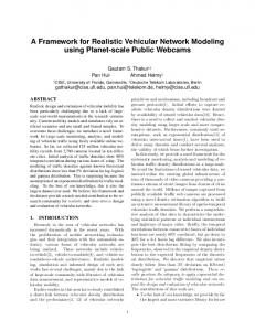
founded projects, such as EuroFOT, have given way to a new set of national and international initiatives. The German simTD, the French SOCOR@F, or the European DRIVE C2X and FOTsis are some examples. Hence, current lines of publicly founded projects are implementing communication stacks that conform with recent standardization efforts, which could be used in FOTs [2]. Many of these initiatives have shown an interest on IPv6 communications, since numerous ITS services will be based on current Internet standards. However, essential issues such as global addressing or network mobility of nodes (i.e. hosts on vehicles) have not been considered in implementations until recent dates. The ITSSv6 project is currently working on this line, proposing an implementation of a communication stack based on current standardized Internet protocols, which is being ported to several FOT initiatives, such as FOTsis and SCOR@F. In parallel to the progress on vehicular communications in research projects, additional efforts have been put on standardizing a communication architecture that assures the future compatibility among different providers. First, the ISO TC 204 released the Communications Access for Land Mobiles (CALM) concept, but the later created group ETSI TC ITS improved CALM based on the results of the COMeSafety European project. The architecture of the current European ITS communication stack [3] (illustrated in Fig. 1) should be instantiated totally or partially on vehicles, nomadic devices, roadside units and central points. As observed, two management and security planes surround four horizontal layers based on the well-known OSI communication stack. The different layers exchange information through a set of well-defined Service Access Points (SAPs). However, the current ITS communication stack lacks on the necessary functionality to achieve continuous communications in such a manner that interactions within the vehicle, with the surrounding environment and directly with nearby vehicles happen in a uninterrupted manner.
Fig. 1: ISO/ETSI reference communication stack
IEEE INTELLIGENT TRANSPORTATION SYSTEMS MAGAZINE, VOL. X, NO. X, OCTOBER 2012
Due to the current deployment of wide-range communication technologies, in the form of 3G access, and the penetration issues that imply V2V communications, it is first envisaged that communications with the infrastructure (V2I/I2V) will be gradually available through technologies such as 802.11p (ETSI G5). It is in the V2I/I2V segment where novel traffic efficiency, comfort services and relaxed safety applications can be initially tested and deployed. This is the reason why this work is especially interested on providing a useful solution for V2I/I2V IPv6 communications. More precisely, based on the concepts standardized by ISO and ETSI, this paper develops a communication stack intended to achieve continuous and secure IPv6 communications by obtaining seamless transitions between points of attachment to the infrastructure. Using as starting point our previous work [4], we have developed an ITS communication stack integrating multiple communication technologies (802.11b/g/n, 802.11p-ETSI G5, WiMAX and 3G/UMTS). Additionally, the IPv6 mobility support provided by the Network Mobility (NEMO) protocol has been enhanced with a handover management system based on the IEEE 802.21 technology, which is an standardized framework for achieving fast and effective handovers in heterogeneous networks. Compared to existing works, the novelty of our proposal is that the developed communication stack follows the standardized ISO/ETSI station reference architecture. The paper is structured as follows. Section II provides a background review about important technologies employed in this proposal. Section III describes the communication stack proposed in the paper. Next, Section IV presents an use case of the optimized handover support, detailing the messages exchanged among the various platform entities. The communication stack is then validated in Section V, presenting the deployed testbed and relevant performance results obtained. Finally, Section VI places the work in the literature and Section VII summarizes the most important conclusions. II. R ELEVANT T ECHNOLOGIES TO ACHIEVE S EAMLESS M OBILITY Mobility is one of the main research topics in wireless networks, due to the benefits offered to end users. For the case of vehicular communications, wireless infrastructures must provide efficient mobility capabilities along the road to maintain vehicles moving at high speed connected to the road operator’s network. In order to cope with this, a vehicle connected to a wireless network should be able to move freely, using different access points that are available along its path. These access points could belong to different administrative domains or, even in the same administrative domain they could also belong to different networks or implement different wireless technologies, like 802.11a/b/g/n, 802.11p, WiMAX or 3G. For this reason, due to this heterogeneity, several types of handovers must be taken into account [5]: a) Intra/inter-network handover: According to the networks involved in the process, during an intra-network handover the vehicle changes between points of attachment
2
deployed within the same network. Conversely, an inter-network handover supposes the vehicle to roam between points of attachment located in different networks. This type of handover implies an IP address reassignment, thus requiring the use of complementary mechanisms such as mobility management protocols. b) Intra/inter-technology handover: Depending on the technology employed before and after the handover, we can distinguish between intra-technology and inter-technology handover. While in the former the vehicle transits between point of attachments based on the same wireless technology, the latter implies the change to a point of attachment employing a different wireless technology. According to current network deployments, inter-technology handovers typically imply a change of network, thus being intimately related to inter-network handovers. c) Intra/inter-domain handover: Depending on whether the new point of attachment is controlled by the same or a different administrative authority, we can distinguish between intra-domain and inter-domain handovers, respectively. Inter-domain handovers are one of the most complex type of handovers since they also imply a change of network (inter-network handover) and a possible change of technology (inter-technology handover). An intra-technology handover is usually referred to as horizontal handover, whereas a vertical handover usually denotes an inter-technology handover. In vehicular communications, each roadside unit could be provided with an attachment point controlled by an access router that manages a network with its own addressing scheme. In this way, changing the attachment point would imply entering a new network. Internet Protocol version 6 (IPv6) is envisaged to be the cornerstone for the future development of ITS services. Both research communities and standardization forums are considering the use of IPv6 as a media-agnostic carrier for non time critical safety applications as well as for traffic management. This interest is based on the numerous benefits brought by IPv6: large addressing space able to cope with ambitious deployment scenarios such as the vehicular one, easier support of management operations related to node auto configuration and native support of security mechanisms thanks to the inclusion of Internet Protocol security (IPsec). Despite current standards in ITS cooperative systems consider IPv6 communications [6], its support is being defined among the different layers of the reference communication stack at the moment. The next parts of this section give an introduction to some of the most important technologies that, in conjunction with IPv6, are considered in this paper to address the network continuity issue within a vehicular communication stack. A. NEMO Network Mobility Basic Support (NEMO) [7] allows terminals within a mobile network to be globally connected to the Internet. Mobility capabilities are distributed between the Mobile Router (MR) and the Home Agent (HA) entities, in order to maintain the IPv6 addressing for the mobile network.
IEEE INTELLIGENT TRANSPORTATION SYSTEMS MAGAZINE, VOL. X, NO. X, OCTOBER 2012
An unchangeable IPv6 Mobile Network Prefix (MNP) is delegated by the home network to MR for assigning addresses to the Mobile Network Nodes (MNN). Following the NEMO model, upon the reception of a Router Advertisement (RA) message from an Access Router (AR), the MR is aware of the existence of a new network. In this case, the MR, which already has a fixed IPv6 address within its home network (Home Address or HoA), generates a new auto configured IPv6 address within the new visited network. This address is called Care-of address (CoA), and it is immediately notified to HA. This notification is performed by the MR through a Binding Update message, which is acknowledged with a Binding ACK sent by HA. Only MR and HA are aware of the network change, since MNNs continue connected with MR using the same address configured using the MNP. Hence, when any computer outside the home network (Correspondent Node or CN) communicates with any of the MNNs, it uses the MNP-generated address as destination and, hence, packets follow the route towards the home network. Then, HA redirects these IPv6 packets to the current IPv6 CoA of MR, which finally distributes the packets within the mobile network. In the same way, when packets are sent from any MNN to a CN, they are routed by MR towards the HA, which forwards them to the destination. As observed, HA and MR perform an IPv6 into IPv6 encapsulation to create a mobility tunnel. B. MCoA MRs can be provided with multiple network interfaces such as IEEE 802.11b/g, IEEE 802.11p, WiMAX or UMTS, for instance. When a MR maintains these interfaces simultaneously up and has multiple paths to the Internet, it is said to be multihomed. In mobile environments, multihoming capabilities can alleviate problems suffered by MRs such as scarce bandwidth, frequent link failures and limited coverage. Multiple Care of Addresses Registration (MCoA) [8] is proposed as an extension of both Mobile IPv6 and NEMO Basic Support to manage mobility in those situations where the MR is simultaneously using multiple communication interfaces. Basically, MCoA defines extensions to allow the establishment of multiple tunnels (distinguished by a Binding Identification number - BID) between MR and HA. This capability is specially useful in vehicular communications, where a continuous UMTS connectivity could be complemented, for instance, with an intermittent 802.11p channel.
3
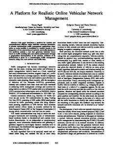
transport within the IP packet. These protocols can be applied in two different operation modes. In transport mode, the security services are applied to next layer protocols, i.e., the information carried within the IP packet. Conversely, in tunnel mode, the protection is applied to the whole IP packet which is sent through a tunnel. The IPsec operation relies on the fundamental concept of Security Association (SA). A SA conceptually represents a secure connection between two entities. The establishment of an SA implies the negotiation of a set of security parameters such as cryptographic algorithms or key material that is used by the AH or ESP protocols. In particular, IKEv2 is an application layer protocol that has been specially conceived to provide such functionality. D. IEEE 802.21 IEEE 802.21 [9] is a media independent handover framework aimed at assisting the handover between heterogeneous networks for providing seamless transitions and continuous connectivity. This is achieved thanks to the definition of a logical entity called Media Independent Handover Function (MIHF), which facilitates the mobility management and handover processes. As depicted in Fig. 2, the MIHF module is located above the media-dependent interfaces (link-layer) and provides a single media independent interface to upper-layers (e.g. mobility protocols). From the MIHF perspective, each node has a set of MIH users (e.g. NEMO) that employ the MIHF functionality to perform handover-related tasks such as monitoring available networks, control the status of active communication interfaces or coordinate the handover execution. The IEEE 802.21 standard defines three types of handover services: •
•
•
Media-Independent Event Service (MIES). This service provides to upper layers information about dynamic changes in link characteristics, link status, etc. Media-Independent Command Service (MICS). This service enables upper layers to control the link behaviour during the handover execution. Media-Independent Information Service (MIIS). This service allows mobile terminals to discover network information within a geographical area, thus enabling a more effective handover decision.
C. IPsec and IKEv2 The IP Security (IPsec) protocol is an enhancement to the basic IP protocol that defines a set of security services for protecting IP traffic. Since it is defined at IP level, the security protection is transparent to other protocols carried over IP. The IPsec packet protection to IP packets can be applied through two security protocols: Authentication Header (AH) and Encapsulating Security Payload (ESP). While the former provides authentication and integrity protection to the IP packet, the latter also provides confidentiality to the data
Fig. 2: IEEE 802.21 framework
IEEE INTELLIGENT TRANSPORTATION SYSTEMS MAGAZINE, VOL. X, NO. X, OCTOBER 2012
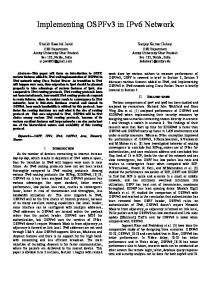
Furthermore, as depicted in Fig. 2, these kind of services can be local or remote. For example, while local MIH Commands are sent by MIH users to the MIHF in the local protocol stack, remote MIH Commands are sent by MIH Users to the MIHF implemented in the protocol stack of a remote entity. Similarly, a MIHF can notify MIH users about events originated by lower layers located either in the local protocol stack or in a remote network entity. Finally, the same behaviour is observed for the information service, since requests from MIH users can be dispatched locally by the MIHF or by a remote network entity. To enable remote communication, the IEEE 802.21 standard defines a protocol for transporting MIH protocol messages between MIH-enabled entities. In particular, the IEEE 802.21 communication model defines an MIH mobile node (MIH MN) that communicates with an MIH Point of Service (MIH PoS), which is a network entity located in the infrastructure that offers MIH services. This communication typically happens through a Point of Attachment (PoA), which represents the network side endpoint offering link layer connectivity. Despite the standard defines different configurations, the most typical scenario consists of an MIH PoS controlling a set of PoAs. Finally, the standard also defines the existence of an MIIS server, in charge of delivering network information requested by MIH entities. III. E NHANCED ITS C OMMUNICATION S TACK The designed communication stack follows the guidelines given by ISO/ETSI communication architecture [10], [11] and, hence, it is usually instantiated in the form of ITS station nodes in vehicles, roadside units and central systems (see Fig. 3). The network design proposed in this paper bets on IPv6-capable technologies for providing V2I and I2V communications. As can observed in the figure, each ITS station type implements a subset of the functionalities of the general communication architecture according to the played role, connectivity requirements and supported applications. For example, while a vehicle host only requires 802.11g to connect with the vehicle’s MR and gain Internet access, the roadside units may use a set of short and medium wireless communication technologies to serve as a network point of attachment for vehicles. Conversely, central systems are mainly accessed through wired communication media (e.g. Ethernet). The remaining of this section details the different features supported by the proposed communication stack, explaining not only the different technologies used but also how they are integrated. A. Secure Multihomed Mobility The designed communication architecture supports a communication model where in-vehicle hosts (e.g., passengers with a tablet PC or an smartphone) can access to the ITS network in a transparent manner, thus not being required to support mobility protocols. To accomplish this objective, vehicles are equipped with a MR in charge of managing an in-vehicle network to which in-vehicle hosts can attach to gain network access. In particular, the MR implements the needed
4
functionalities to maintain global reachability of the in-vehicle network and hide mobility tasks to in-vehicle hosts. Fig. 3a depicts the communication stack instantiation for in-vehicle hosts (stack on the left) and MRs (stack on the right) located within a vehicle ITS station. As observed, hosts include standard networking functionality already implemented by commercial mobile devices. On the one hand, the lower layer is based on typical technologies for wired (e.g. Ethernet) and wireless (e.g. 802.11b based WiFi) connectivity. Additionally, a GPS device could be part of the lower layer to enable the host to be geo-located. On the other hand, the networking and transport layer is based on IPv6 and typical middleware protocols such as Transport Control Protocol (TCP) and User Datagram Protocol (UDP). Unlike in-vehicle hosts, the MR is equipped with additional modules due to this entity is responsible for supporting mobility of the in-vehicle network. First, in the lower layer, we find technologies used for communicating with in-vehicle hosts and roadside units. Regarding the former, as described in the host communication stack, common wired and wireless technologies are employed. For communicating with the infrastructure, the designed communication stack contemplates the use of multiple external communication interfaces: 3G/UMTS, WiMAX, 802.11a/b/g and 802.11p. 802.11a/b/g is considered in infrastructure mode, while 802.11p is used for one-hop communication with roadside units. In the networking and transport layer, several elements have been included to support secure mobility of the in-vehicle network. The core feature of this part is the Network Mobility (NEMO) module, which is in charge of maintaining reachability for the whole in-vehicle network. Among the available alternatives for IPv6 mobility management support in vehicular networks [12], NEMO has been selected due to its wide usage and the existence of implementations. According to the NEMO operation, the MR is delegated a MNP by the home network. When the MR changes of location (i.e., performs a handover to a new point of attachment), the HA is notified of the new CoA. Therefore, the network traffic destined to the MNP is redirected by the HA to the MR via an IPv6 over IPv6 tunnel. To support the multihomed configuration of the MR, NEMO operation is assisted with MCoA. Thanks to these extensions, network mobility in the MR is maintained across multiple interfaces and the HA is aware that the MR is reachable through multiple interfaces (i.e., through a set of CoAs). Apart from the modules in charge of mobility-related operations, the MR is equipped with the needed elements to secure mobility-related traffic exchanged with the HA by means of IPsec [13]. As we observe in Fig. 3a, IPsec employs security associations (stored in the security plane) which are negotiated by means of IKEv2, based on pre-established security policies. In turn, IKEv2 uses EAP [14] to perform mutual authentication between MR and HA, a mandatory step prior to the SA establishment. The communication stack employed by ARs is depicted in Fig. 3b. To provide connectivity to the roadside infrastructure, its communication stack consists of the required IPv6
IEEE INTELLIGENT TRANSPORTATION SYSTEMS MAGAZINE, VOL. X, NO. X, OCTOBER 2012
5
(a) Vehicle ITS Station
(b) Roadside ITS Station
(c) Central ITS Station
Fig. 3: Communication stack design
functionality operating over different lower layer technologies: wireless interfaces for communicating with MRs and wired interfaces to connect with the roadside operator’s network infrastructure. Finally, Fig. 3c shows the communication stack instantiation for a server located in the central ITS station. In addition to other functionalities (described in next section III-B), this entity acts as HA and, consequently, deploys the same modules described for the MR to implement mobility and security operations. B. Vehicular handover management One of the most critical aspects in vehicular communications relies on the definition of a mechanism enabling a constant and reliable access to the infrastructure. As explained in section III-A, the MR of the vehicle is
equipped with multiple interfaces. This allows a multihoming operation using NEMO and MCoA protocols. Nevertheless, this capability is not enough to achieve vehicle mobility without communication interruptions. Apart from this multihoming capabilities, it is necessary some mechanism destined to maximize the network connectivity of each interface by determining both the most appropriate point of attachment and when to perform a handover. To provide this functionality, IEEE 802.21 technology has been integrated within the proposed communication stack. The integration of the IEEE 802.21 framework within the communication stack brings important benefits. On the one hand, as described in section II-D, the important advantage of IEEE 802.21 is that the handover services are made available to upper layers applications in a media independent fashion.
IEEE INTELLIGENT TRANSPORTATION SYSTEMS MAGAZINE, VOL. X, NO. X, OCTOBER 2012
i.e., upper layers can invoke these services regardless the specific link layer technology. This is of paramount importance for future vehicular systems, since current standardization efforts consider that communications will happen through different access technologies. On the other, IEEE 802.21 supports handovers between heterogeneous networks that can be either mobile-initiated and network-initiated, thus being adaptable to different handover schemes that may appear in vehicular communications. To correctly integrate the IEEE 802.21 framework within the ITS scenario, we must both determine how the different IEEE 802.21 entities are implemented in the reference ITS communication architecture and integrate the IEEE 802.21 framework within the communication stack. Regarding the former, we propose the following correspondence: •
•
•
•
The MR will implement the MIH MN functionality, since this entity is responsible for the handover in the vehicle ITS station. Note that in-vehicle hosts are not required to implement IEEE 802.21 because the handover is managed by the MR and, consequently, they are not required to participate in the process. The access point located in the roadside ITS station will represent the MIH PoA, since this entity is the link-layer endpoint of the ITS network. The AR of the roadside ITS station will implement the MIH PoS functionality. Despite other configurations are also possible, we have opted for this configuration that favours the deployment since only roadside access routers must be updated to support MIH functionality in the roadside infrastructure. The server implementing the MIIS service is deployed by the road operator and located within the central ITS station. This server stores information about the different networks managed by the road operator that is delivered to MIH MNs (i.e. MRs) when requested.
With regard to the integration of the IEEE 802.21 framework within the communication stack, the most important decision relies on the situation of the MIHF module. In this sense, as observed in Fig.3, we have opted for placing the MIHF module in the management plane. This decision is based on several reasons. First, according to the ISO/ETSI specifications [10], [11], the management plane is in charge of managing communication links and, among other functionalities, is responsible for controlling the handover process of each interface. For this reason, it seems reasonable to put the MIHF module in the management plane since this is precisely its functionality. Second, considering that MIH services should be made accessible to any module (MIH user) located in the Networking and Transport, Facilities or Applications layer, the location of the MIHF in the management plane allows to expose the MIHF services through the SAPs between the management plane and these layers. Third, the placement of the MIHF in the management plane facilitates the MIHF operation. On the one hand, the MIHF can be in contact with the specific link-layer technologies through the SAP connecting the management and access layer. On the other hand, the communication
6
capabilities needed by the MIHF to exchange MIH messages with remote entities can be implemented either at network (by interacting with the IPv6 protocol block) or link layer (by interacting with the specific access technologies). In fact, current specifications in ISO [15] already conceive that modules located in the management plane can use the transport services for the purpose of remote communication between management planes of ITS station nodes. Another interesting aspect worth discussing is related to the interaction between the MIHF and the access technologies. The MIHF is an abstraction module allowing MIH users to employ handover services (e.g. solicit the activation of an interface) without being aware of the particular details of the specific technology. The MIHF implements the generic services invoked by MIH users using the specific services offered by each link-layer technology. This communication between the MIHF and the access technologies happens through the existing SAP between the management and access layer. It is over this SAP where a mapping between generic MIH services and the specific functionality offered by link technologies is implemented. For the interested reader, the IEEE 802.21 standard [9] provides a guidance about this correspondence for relevant technologies like the ones included in our communication stack. The handover management solution we present is not limited to simply integrate the IEEE 802.21 framework into the communication stack but also defines the necessary functionality to enable optimized handovers. As observed in Fig.3, depending on the type of node, we have defined several modules that, acting as MIH users, will use the MIH services to achieve seamless handovers and avoid communication disruption. In the following, we explain in detail the different modules defined for the MR, AR and central server. 1) Handover management in the Mobile Router: The MR plays an important role in the handover management since this entity acts as MIH MN and will be in charge of controlling the vehicle handover among ARs located along the road. As observed in Fig.3a (stack on the right), the management plane of this entity will maintain a Management Database (MD) containing information that will be used by other modules (described below) responsible for performing handover related tasks. The information contained in the MD has already been partly specified by ISO [15] and covers the following aspects: • Network interfaces status: for each communication interface it is maintained relevant information like type of technology, link-layer address (e.g. MAC) or interface status (active, connected, suspended, etc.). • Network interfaces performance parameters: this refers to information describing specific properties of the network interfaces like data rate, cost, reliability, etc. • Application requirements: for every application it is maintained information about the required communication capabilities like minimum data rate or delay, maximum cost or required networking protocols. • Network information: the MD will also maintain information about available networks either being used or that are available and could be potentially accessed
IEEE INTELLIGENT TRANSPORTATION SYSTEMS MAGAZINE, VOL. X, NO. X, OCTOBER 2012
after a handover. Example of relevant information is the network type, service provider, level of security, data rate or cost. The information contained in the MD feeds two new modules called Handover Decision Module (HDM) and Flow Management Module (FMM). These modules carry out their operation by using relevant information from the MD. In particular, the HDM controls the handover itself and decides not only when to perform a handover over certain interface, but also selecting the network to which roam. The HDM uses different information available in the MD like application requirements, available networks in the vicinity or status of communication links. The decisions made by the HDM are communicated to the mobility management protocols located in the networking and transport layer (NEMO/MCoA) that are ultimately responsible for executing the handover. The FMM complements the HDM functionality since it is responsible for distributing the application traffic over the network interfaces. The FMM operation also takes as input information maintained in the MD like user preferences, connectivity requirements demanded by applications, interface status and or information about access networks. The decisions made by the FMM regarding the traffic flow organization are communicated to the networking and transport layer in order to update the forwarding tables with proper routing policies. The operation of the HDM and FMM modules is not only supported by the information available in the MD but they also rely on the MIH services offered by the MIHF. The communication between these modules with the MIHF is based on the well-defined service primitives specified in the IEEE 802.21 standard [9]. For example, the HDM will typically use the MIH services to be informed of changes of link status by subscribing to MIES, recover additional information about neighbouring networks by using the MIIS or start the handover process by using the MICS. Similarly, the FMM operation will be supported by the MIHF services when soliciting information about network operators through the MIH information service. For more information on this aspect, please refer to section IV where we provide an use case example describing the type of information exchanged among the different modules during a handover. 2) Handover management in the Access Router: The communication stack of the AR also integrates IEEE 802.21 handover services since this entity acts as MIH PoS and plays an active role to assist the vehicle handover. In particular, the AR will exchange MIH messages with the vehicle MR to coordinate during the handover. For example, the MRs need to consult candidate ARs their capacity of holding a handover or solicit the reservation of resources (e.g. bandwidth). Similarly, communication between MR and AR is necessary to notify when a handover is initiated and finished, as well as for releasing resources when MRs abandon the coverage area controlled by an AR. With the support of the MIH services, the handover related taks on the AR are performed by a new module called Handover Controller Module (HCM). The HCM is located in the management plane and interacts with the MIHF by invoking MIES, MICS and MIIS services.
7
3) Handover management in the central server: The IEEE 802.21-based handover management requires the road operator to deploy a server supporting the MIH information service. This server will maintain information about the road operator’s network and manage information requests received from MIH-enabled entities. Without loss of generality, Fig.3c depicts a stack instantiation for a server acting as both MIIS and HA. Nevertheless, it is worth noting that these functionalities can be deployed in different physical servers within the central ITS station. As observed, the management plane includes a MIHF module, which is the basic component of the IEEE 802.21 framework. In this case, there only exists one module acting as MIH user called MIIS Module (MIISM). The MIISM implements the MIIS service itself and processes MIH network information requests. The MIISM uses the Network Database (ND) that contains information about the different networks deployed by the road operator. The information contained in the ND follows the guidelines provided by the IEEE 802.21 standard [9], where three different categories are distinguished: • Network provider information: country, network provider identifier, etc. • Access networks information: network identifier, roaming partners, cost, data rate, access network capabilities, supported mobility protocols, etc. • Point of attachments information: access technology, link-layer address (e.g. MAC), geographical location, supported security protection, etc. C. Application support The stack on the left in Fig. 3a represents an in-vehicle host, which is in charge of executing final applications that could access remote services. As explained in Section III-A, a GPS device in the lower layer enables the host to be geo-located while the networking middleware includes TCP and UDP. An essential part of the host protocol stack is, however, the facilities layer. As can be seen in Fig. 3, a Java virtual machine is used as the basis for the Open Service Gateway Initiative (OSGi) framework. OSGi acts as the manager of the lifecycle of middleware parts and applications, and makes easier the communication among software modules installed in the host. Above OSGi, the most relevant facilities are: the Session Initiation Protocol (SIP), which is used by the IP Multimedia Subsystem (IMS) client as an enabler for signaling communications; the IMS client, which is directly used by applications to access remote services in a normalized way; and the Presence Service, also described in IMS specifications, which could be directly used by applications that depend on the terminal status (location, temperature, vehicle in emergency state, etc.). More details about the IMS integration performed for accessing ITS services can be found in a previous work [16]. IV. M OBILITY U SE C ASE E XAMPLE For a better understanding of our solution, in the following we present a usage scenario in order to show how the different features supported by the proposed ITS communication stack
IEEE INTELLIGENT TRANSPORTATION SYSTEMS MAGAZINE, VOL. X, NO. X, OCTOBER 2012
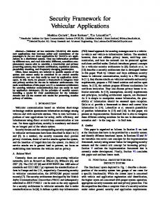
can optimize the handover process in V2I communications. In the scenario, we suppose a vehicle ITS station moving across a highway managed by a roadside operator that deploys both a roadside and a central ITS station. While the roadside ITS station consists of several ARs offering wireless connectivity to vehicles, the central ITS station holds the core network of the road operator, where ITS services are implemented. In our case, without loss of generality, we assume a roadside ITS station integrated by two ARs offering wireless connectivity through 802.11p (AR1) and WiMAX (AR2). Similarly, the central ITS station comprises a single server implementing the HA and MIIS servers. Throughout the use case example, we are going to refer to MIH services defined in the IEEE 802.21 standard [9]. We follow the name convention MIH Service Primitive, where “Service Primitive” refers to the specific type of MIH service. Also note that, in the diagram, normal formatting is used to indicate MIH services locally demanded between modules of the same entity, and bold formatting is reserved to indicate messages remotely exchanged between modules of different entities. It is worth clarifying that, for simplicity, the use case explanation focuses on the MIH messages exchanged over the network between the different entities. Nevertheless, the reader can easily realize in the diagram that these messages are exchanged as a consequence of local communication through MIH service primitives among MIH Users, MIHF and lower layers within a stack. Let us suppose a vehicle’s MR communicating with the AR based on 802.11p technology (AR1). The HDM of the MR is subscribed to receive events from lower-layer and receives a notification from the MIHF (MIH Link Going Down) indicating that the 802.11p interface connectivity loss is imminent1 After checking available networks from the MD database, the HDM concludes that the best decision is to perform an intra-domain, inter-network and inter-technology handover to AR2. As depicted in Fig. 4, the handover process takes place in four different phases: 1) Handover preparation. The handover begins when the MIH MN (located in the MR) notifies the current MIH PoS (located in AR1) the intention of performing a handover to AR2 by sending an MIH MN HO Commit request message. Upon the reception of this message, the current MIH PoS solicits a resource reservation in the target MIH PoS (located in AR2) by sending an MIH N2N HO Commit request message that contains a set of resource parameters (e.g. bandwidth or packet delay). If the target MIH PoS manages to reserve requested resources for the MIH MN, the current MIH PoS is notified with an MIH N2N HO Commit response message. The process finalizes when the current MIH PoS informs the MIH MN by sending an MIH MN HO Commit response message, informing that the network is ready to afford the handover. 2) Link-Layer connectivity establishment. In this phase, the MR performs the physical link switch to the target 1 Due to the ad-hoc nature of IEEE 802.11p, the implementation of certain MIH service primitives is not trivial and needs to be carefully analyzed.
8
AR (AR2). Through the MIH Link Actions.request service primitive, the HDM solicits the MIHF the activation of the WiMAX interface. The MIHF invokes the specific Link Action.request primitive particular to the WiMAX technology and, once the interface is activated, the HDM is informed through the MIH Link Actions.confirm primitive. After that, the link-layer connectivity establishment tooks places following the specific procedure associated to the WiMAX technology. Once the connectivity is established, both MIH MN and target MIH PoS are notified by the MIHF through the MIH Link Up.indication service primitive. 3) Handover execution. In the next step, the HDM solicits the mobility protocols (NEMO/MCoA) to perform the management procedures. For the sake of simplicity, note that in Fig. 4 this functionality is grouped within a module called Upper Entity (UE). According to the features supported by the proposed communication stack, this phase may imply the new CoA configuration when the network prefix is announced by AR2, the duplicate address detection (DAD) 2 process to verify that the configured CoA is unique within the access network, and the notification of the new CoA to the HA located in the central ITS station. 4) Handover finalization. When the handover is completed and the traffic flow enabled through AR2, the MIH MN sends an MIH MN HO Complete request message to the target MIH PoS. Upon reception of this message, the MIH PoS informs about the handover completion to the previous serving PoS (MIH PoS in AR1) through an MIH N2N HO Complete request. This notification is useful for AR1, since resources allocated for the MR can be released. When the target MIH PoS receives an MIH N2N HO Complete response from the previous MIH PoS informing that resources have been successfully released, it sends a final MIH MN HO Complete response message to the MIH MN. As we can observe, the IEEE 802.21 framework assists the handover execution when the MR changes between point of attachments to the infrastructure. The MIH services enable to precisely detect the need of performing a handover and to carry out its execution in a coordinated way between the involved entities. Despite Fig. 4 depicts a basic use case, it is worth mentioning that IEEE 802.21 is flexible enough to support handovers controlled not only by the MR but also by the roadside operator’s network. V. C OMMUNICATION S TACK VALIDATION The communication stack presented in the paper has been validated by setting up a testbed including most of the capabilities described above, and evaluating its operation through an experimental assessment in a real urban environment. 2 The use of IP protocols based on multicast in IEEE 802.16 networks requires the application of some mechanisms as described in [17].
IEEE INTELLIGENT TRANSPORTATION SYSTEMS MAGAZINE, VOL. X, NO. X, OCTOBER 2012
Fig. 4: IEEE 802.21-assisted handover in cooperative ITS
9
IEEE INTELLIGENT TRANSPORTATION SYSTEMS MAGAZINE, VOL. X, NO. X, OCTOBER 2012
Fig. 5: Deployed scenario
A. Testbed Description As observed in Fig. 5, the set-up scenario consists of one vehicle, one roadside station and the home central ITS station for the vehicle. This equipment has been deployed at the University of Murcia, near the Faculty of Computer Engineering and taking advantage of the ring road that surrounds the campus. By means of the three communication interfaces of the MR, the vehicle ITS station can be connected with roadside units supporting 802.11b/g/n, 802.11p, or directly with the central ITS through the 3G/UMTS network. In the last case it is necessary to provide an IPv4 to IPv6 transition solution, since most of the 3G providers (including the used one) still offer IPv4 Internet. In this case, OpenVPN is used between the MR and an AR within the central ITS station. Communications through our 802.11b/g/n and 802.11p roadside units are directly performed using IPv6, since the University of Murcia infrastructure supports this protocol natively. Home Internal Router and the ARs in Fig. 5 execute a common communication stack with IPv6 features. Additionally, the router included in the Central ITS Station also serves as the ending point of the OpenVPN tunnel when 3G is used. The Border Router element uses an IPv4/IPv6 dual stack, since it provides Internet connectivity to the ITS network. Additionally, this border router offers network address translation from IPv6 to IPv4 (NAT64) and a domain name system for getting IPv6 addresses of external IPv4 services (DNS64). In this way, it is possible to provide access to IPv4 resources on the Internet. The Vehicle Home Network is where the vehicle maintains its home addressing. In other words, when any computer outside this network communicates with the vehicle host, it uses the home IPv6 address and
10
packets follow the route towards the home network (within the central ITS station), and the NEMO Home Agent (HA) will redirect these IPv6 packets to the current IPv6 address of the vehicle, which is assigned to the MR by each visited roadside station. The other important part of the central ITS station is the service centre, which is in fact distributed in a set of nodes that run the IMS core network. Connected with the IMS core, an application server hosts the various services offered to vehicles. According to the design presented in Section III, the developed prototype implements most of the network entities and modules comprising the communication stack. The basic mobility and security capabilities are exploited in a recent work [18]. Regarding the vehicular handover management, IEEE 802.21 is a technology recently standardized and, for the time being, there no exists mature implementations [19] that can be integrated within our communication stack. For this reason, the presented stack prototype does not include all the envisaged handover management features, but implements essential parts of the described architecture to assist the handover. This way, part of the flow management functionality is currently modeled with the BID used by NEMO/MCoA when a new CoA is registered with the HA. Upon the reception of a Router Advertisement message from a new network, the NEMO daemon adds a new routing entry in the Linux kernel of the MR with a priority assigned in accordance to the BID of the communication interface involved in the communication. These BIDs are set in order to assist the handoff decision by selecting 802.11p and 3G, in this preference order. The handover management logic is currently implemented in the form of an automatic CoA registration with the HA upon the detection of a new network when a Router Advertisement message is received from a new AR. Networks are understood to be unavailable when no Router Advertisement messages are received from the corresponding AR after a configurable timeout period. Several software modules have been also implemented over the network and transport layer for the case of the host. The most representative ones are the IMS service access layer, the OSGi middleware to host all facilities and applications, and a generic human-machine interface (HMI) for presenting applications in a unified way to the user. The capabilities have been previously presented in [16] and [4]. The list of hardware and associated software used for each node can be found in Table I. B. Performance Analysis In the tests included in this section, the vehicle moves within the Espinardo Campus (University of Murcia), using the previous testbed to evaluate the handoff operation and the network performance from the application perspective between 3G (UMTS) and 802.11p. NEMO, IPsec and IKEv2 are enabled. Additionally, the MCoA extensions are disabled in order to better appreciate the performance degradation caused by the handover. A roadside unit connected on the top of the Faculty of Computer Science is used as 802.11p network attachment point. This has been installed to only give 802.11p
IEEE INTELLIGENT TRANSPORTATION SYSTEMS MAGAZINE, VOL. X, NO. X, OCTOBER 2012
11
TABLE I: List of hardware equipment Networked nodes Node
Model
CPU/Mem
Operating System
PC Viliv X70
Atom 1.3Ghz/1GB
Windows 7
Mobile Router
Commsignia Laguna
Dual Core ARM11/128MB
Modified ITSSv6 distribution
Access Router
Commsignia Laguna
Dual Core ARM11/128MB
ITSSv6 distribution
mini-ITX PC
Via 532Mhz/476MB
Ubuntu 10.4
PC
i5 3.1Ghz/3GB
Ubuntu 10.4
IMS core x 4
Xen virtual machine
PentiumD 2Ghz/256MB
Ubuntu 10.4
IMS Apps Server
Xen virtual machine
PentiumD 2Ghz/1GB
Ubuntu 10.4
Vehicle Host
Home Agent Central ITS AR
Network interfaces Technology 3G/UMTS 802.11p
Hardware Ovation MC950D modem Unex DCMA-86P2 mini-PCI (integrated in AR and MR) Relevant software
Node Vehicle Host
Description OSGi Equinox framework 3.6
Mobile Router
NEMO (UMIP 0.4), IKEv2 (OpenIKEv2 0.96) and RA daemon (radvd 1.8)
Access Router
RA daemon (radvd 1.8)
Home Agent IMS core IMS Apps Server
NEMO (UMIP 0.4) and IKEv2 (OpenIKEv2 0.96) Fraunhoffer Open IMS Kamailio 3.1.2
coverage to a small stretch of a near road. A common vehicle mounting the on-board equipment drives around the building at a urban-like speed between 20 and 40 km/h and, when it is in the communication range of the roadside unit, the MR automatically performs a handoff from 3G to 802.11p. The next three metrics have been considered in three independent tests: •
•
•
Bandwidth, measured in Mbps. It has been evaluated with a TCP flow maintained at the maximum allowable speed from the vehicle host to a CN connected within the central ITS station network. Packet Delivery Ratio (PDR), measured in percentage of packets lost. It has been evaluated with a UDP flow in the downlink direction at 500 Kbps from the CN to the vehicle host. The UDP packet size has been set to 1470 bytes. Round-trip delay time (RTT), measured in ms. It has been evaluated with ICMPv6 traffic generated from the vehicle host to the CN. ICMPv6 Echo Request messages have been generated at a 1 Hz rate with a size of 64 bytes.
UDP and TCP traffics have been generated with the Iperf utility3 (version 2.0.4), while the ICMPv6 traffic has been obtained from the common Ping6 Unix command. The period of RA notifications from the AR is set to a random time between three and four seconds (to avoid RA collisions with possible nearby ARs). Additionally, the expiration time of the pair CoA-HoA used is set to 30 seconds in both the MR and the HA. The bandwidth results obtained in the TCP tests are showed in Fig. 6. As can be seen, the slow-start algorithm of TCP tries to adapt to the wireless medium during the whole test, 3 http://sourceforge.net/projects/iperf/
affected by the mobility of the vehicle. The first handoff from 3G to 802.11p occurs at time 310 s (6b), and the second one, from 802.11p to 3G, at time 445 s (6c). At these moments the data rate is null for a while, due to the time needed to change the CoA used against the HA. Nevertheless, the connectivity gap is more evident in the second handoff, due to 802.11p technology is preferred when both 3G and 802.11p technologies are present. The handover mechanism waits for a Router Advertisement through 802.11p interface but, if this is is not received, the CoA-HoA association timeout indicates that the 802.11p connectivity is over and the handoff to the 3G technology is performed. This effect is also noticeable in the rest of the tests. Moreover, it is evident the quite better performance obtained while the 802.11p link is maintained, with peaks near to 6 Mbps. Between times around 100 and 200 s the HSPA (High Speed Packet Access) channel allocation algorithm adapts better, since the vehicle moves near the UMTS base station. It can be noted that the performance of the 3G link is similar at the beginning and the end of each test because the circuit is circular. Regarding packet looses, the PDR results for the UDP data transfer are plotted in Fig. 7. A performance degradation has not been observed in the first handoff, as can be seen in Fig. 7b, but the second handoff implies two seconds of null connectivity (Fig. 7c). Moreover a great number of packet looses appear while the 802.11p link is used. This is explained by the fact that the 802.11p channels are located in the 5.9 Ghz band, given to suffer more from obstructions to the signal propagation, such as other vehicles, building blocks or vegetation. Finally, the network latency has been evaluated and results are given in Fig. 8. These results have been obtained by generating ICMPv6 traffic from the vehicle host to the CN. As
IEEE INTELLIGENT TRANSPORTATION SYSTEMS MAGAZINE, VOL. X, NO. X, OCTOBER 2012
6000
can be seen in the results, the 802.11p area is clearly visible with most of the RTT values under 10 ms, while 3G RTT results are more scattered (consider the logarithmic scale in the ordinate). Losses only appear during the second handoff depicted in Fig.8c. Here four messages are lost until the UMTS link is again used.
umts wifi 5000
4000 Bandwidth (Kbps)
12
3000
2000
1000
0 0
100
200
300 Time (s)
400
500
600
(a) Bandwidth obtained during the whole test
(a) RTT delay obtained during the whole test
(b) First handoff
(c) Second handoff
Fig. 6: Maximum bandwidth using TCP
(b) First handoff
(c) Second handoff
Fig. 8: RTT delay using ICMPv6 Echo/Request traffic at 1 Hz
(a) PDR obtained during the whole test
(b) First handoff
Considering the results, network mobility and security modules perform efficiently under real inter-technology handoffs, the most difficult to accomplish. The communication stack operates correctly, maintaining the in-vehicle network connectivity in all tests and showing performance results that enable the communication stack to be used in many vehicular services. Unless high-quality multimedia transmissions are required, the bandwidth results indicate that the data rate required by most of the traffic efficiency and comfort cooperative services can be covered and, according to latency tests, even non-critical security services could be implemented, such as emergency assistance, variable traffic signaling or kamikaze warning. Moreover, it is important to remark that this infrastructure-based vehicular communication approach is a real solution that could deployed in the short term and it is also capable of allowing indirect V2V communications, thanks to the global IPv6 scope of all in-vehicle hosts.
(c) Second handoff
Fig. 7: PDR using UDP flow of 500 Kbps
VI. R ELATED W ORK The research community is concerned with the problem of providing network continuity in vehicular communications. In particular, the continuity in IPv6 communications is
IEEE INTELLIGENT TRANSPORTATION SYSTEMS MAGAZINE, VOL. X, NO. X, OCTOBER 2012
known to be a requisite of paramount importance for traffic efficiency and infotainment applications relying on IP-based communications. Existing works in the literature have addressed the problem considering the mobility management problem. For example, authors in [20] propose a new mobility protocol based on PMIPv6 to speed up the tasks associated to mobility management of vehicles. The same objective is addressed by the work presented in [21], but developing a mobility procedure at link-layer. Unlike existing works, our proposal completely relies on standardized technologies to manage not only the vehicle mobility (i.e. NEMO), but also securing the process (i.e. combining IKEv2 and IPsec). In [22] the authors review the NEMO applicability in vehicular communications and lists the current lines for optimizing its operation. A key technique identified here to improve the operation of NEMO is MCoA, which has been considered in the proposal included in this paper for speeding up the handover and adding potential flow management strategies. Additionally, in [22] the security is identified as one of the prime challenges in NEMO-based vehicular communications. As said, our proposal, based on IPsec and IKEv2, deals with this requirement. Additionally, another noteworthy weakness of existing works is that they completely ignore other problems associated to the provision of network continuity. In this sense, this work presents a novel architecture to achieve seamless and smooth handovers by applying the standardized IEEE 802.21 framework. In fact, this is a novel research topic that has been little explored and only a few works can be found proposing the assistance of IEEE 802.21 technology to vehicular communication handovers. For example, authors in [23] present a proposal for integrating an extended set of IEEE 802.21 primitives with NEMO and MCoA, anticipating the handover by registering a new CoA as soon as it is detected that the signal strength of current link is under a certain threshold. Nevertheless, this proposal does not consider the ISO/ETSI station reference architecture, which constitutes the base for the development of future vehicular communications. Authors in [24] develop an IEEE 802.21-assisted handover for vehicular communications that considers the vehicle as a single entity, thus not contemplating the existence of an in-vehicle network as proposed by ISO/ETSI standards. The same idea is applied in [25], where some IEEE 802.21 handover services are integrated within a specific ITS architecture developed by the GeoNet project that does not follow the ISO/ETSI concepts. A recent work presented in [26] presents an hybrid V2V/V2I communication model to provide Internet access to vehicles using WLAN and 3G communications. This work presents an interesting base, where NEMO is also used together with IEEE 802.21 in a descriptive design, although architectural and development details are not given about the integration of these functionalities on a communication stack. Finally, another work is conducted in [27], where authors present an initial proposal for implementing the MIIS service in vehicular networks with the aim of assisting vehicles in handovers. Nevertheless, this work is not aligned with the ISO/ETSI communication model. Another noticeable contribution of this work relies on the
13
development not only of a complete communication stack but also of a testbed which allows the experimental evaluation of vehicular networks. In fact, this is an aspect not frequent in the literature due to the tough design and development efforts needed. In the context of FOT projects, since they are intended to supply a framework for implementing integral communication modules, one could find some articles in this line. The authors of [28], for instance, present the testing framework for the DRIVE C2X project, including test methodology, system specification and implementation, tools for text execution, etc. Nevertheless, this work is not concerned with the use of IP-based communications that are left out for management and testing purposes. As individual contributions, the work presented in [29] develops an experimental testbed to validate an on-board solution for providing vehicular communications through a “car gateway”, which is similar to the concept of MR. However, this solution is highly coupled with the vehicular platform and does not follow the ISO/ETSI guidelines recommending the development of a generic communication stack that can be instantiated on the different elements of an ITS network. The work presented in [30] is nearer to the testbed and tests presented in this paper, although a constrained communication stack is used for an experimental evaluation of a concrete routing and flow management subsystem. Results here expose a NEMO behavior similar to the results reported in this paper, allowing in this case a manual change between 3G and WiFi. Results are slightly better in our tests, which is attributed to the improvement of UMTS networks in the last years and the use of 802.11p communications. Nevertheless, no security measures are evaluated here and, as far as the authors know, in any other paper regarding IPv6 vehicular communications. In [31] a recent evaluation of NEMO and MCoA in a real environment with two WiFi access points supports our idea of integrating this synergy to reduce the handover delay, however, the good results obtained in this work (no data looses during handovers) are attributed to the limited testbed where a trolley is used to move the “on-board” equipment. This scenario is far from the real evaluation carried out in this paper in a urban environment. Although there are not prior works on network mobility evaluated on the top of 802.11p, according to the authors background, it is interesting to bear in mind some recent works analyzing this technology at link level in vehicular field trials. Initial packet delivery ratio tests have been carried out in [32], according to the Received Signal Strength Indication (RSSI) at the MR and the distance to be access point. Comparing with our results, better communication ranges are obtained, up to 800 meters, but these tests have been performed in a straight road with direct line of sight, and our scenario considers a more common case where buildings and vegetation complicate communication. Although the results are analyzed from the link layer point of view, the data traffic has been generated using IPv6 UDP flows. The work presented in [33] describes an exhaustive evaluation of roadside to vehicle communications using 802.11p and, in addition to the conclusions given in [32], it is said that vehicle speed does not cause a great performance degradation when
IEEE INTELLIGENT TRANSPORTATION SYSTEMS MAGAZINE, VOL. X, NO. X, OCTOBER 2012
this communication technology is used. Packet delivery ratio decreases 6% and network latency increases 0.8 ms when vehicle speed varies from 20 km/h to 100 km/h. Authors in [34] performs a similar evaluation, but this time carrying out a great testing campaign in a city. The most interesting analysis is the one attending to the impact of the physical environment in the expected performance of the network. In our case, the signal blockage of the surrounding buildings bound the 802.11p communication area. In summary, unlike the work presented in this paper, we can point out that existing contributions are not focused neither on integrating IEEE 802.21 in the reference ISO/ETSI ITS communication architecture, nor on the experimental validation of mechanisms enabling continuous and secure IPv6 vehicular communications. VII. C ONCLUSION The achievement of a continuous IPv6 communication experience is a sine qua non for the development of future ITS services, specially those related with the traffic efficiency and infotainment applications. For this reason, future cooperative ITS systems require the urgent development of mechanisms enabling an uninterrupted network access. In this paper we have developed an ITS communication stack supporting secure multihomed mobility of the vehicle as well as handover optimization by using the IEEE 802.21 standard. Taking as reference the standardization efforts jointly developed by ISO and ETSI, the proposed stack achieves these features by integrating standardized technologies for the support of network mobility (NEMO), multihoming (MCoA), mobility traffic securization (IPsec and IKEv2) and handover management (IEEE 802.21). Additionally, the communication stack has been provided with facility layer features through the use of OSGi and IMS overlay capabilities. A real case of study is also presented by using a real testbed and analyzing a set of experimental trials where handoffs occurs between 3G and 802.11p technologies. This demonstrates how the proposed communication stack assists the handover optimization and paves the way towards a seamless transition between attachment points in vehicular networks. Future work lines comprise a tight integration of IEEE 802.21 primitives with the network mobility subsystem, in the line presented in [35], and an exhaustive analysis of the IPv6 networking part regarding the improvement of the presented IEEE 802.21 enabled mobility features with security capabilities. In this sense, it is our priority to study the integration of the recently approved IEEE 802.21a [36] standard within the ITS architecture, since this security extension is expected to optimize the network access control process performed during the handover. In this sense, we also plan to explore other alternatives allowing to optimize the handover execution itself since some processes like DAD are known to be costly processes. Finally, it is worth mentioning our intention of conducting more exhaustive tests using the experimental testbed developed in this research work and simulating the operation of the network continuity solution in realistic vehicular scenarios.
14
ACKNOWLEDGMENT This work has been sponsored by the European Seventh Framework Program, through the ITSSv6 (contract 270519) and FOTsis (contract 270447) projects; the Ministry of Science and Innovation, through the Walkie-Talkie project (TIN2011-27543-C03); and the Seneca Foundation, by means of the GERM program (04552/GERM/06). R EFERENCES [1] C. Weib, “V2X communication in Europe: From research projects towards standardization and field testing of vehicle communication technology,” Computer Networks, vol. 55, no. 14, pp. 3103 – 3119, 2011. [2] A. Festag, L. Le, and M. Goleva, “Field operational tests for cooperative systems: a tussle between research, standardization and deployment,” in Proceedings of the Eighth ACM international workshop on Vehicular inter-networking, ser. VANET ’11. New York, NY, USA: ACM, 2011, pp. 73–78. [3] T. Kosch, I. Kulp, M. Bechler, M. Strassberger, B. Weyl, and R. Lasowski, “Communication architecture for cooperative systems in Europe,” IEEE Commun. Mag., vol. 47, no. 5, pp. 116 –125, may 2009. [4] J. Santa, P. J. Fern´andez, A. Morag´on, A. S. Garc´ıa, F. Bernal, and A. F. G´omez-Skarmeta, “Architecture and development of a networking stack for secure and continuous service access in vehicular environments,” in 19th ITS World Congress, October 2012, pp. 1 – 12. [5] N. Nasser, A. Hasswa, and H. Hassanein, “Handoffs in Fourth Generation Heterogenous Networks,” IEEE Communications Magazine, vol. vol. 44, no. 10, pp. pp. 96–103, Oct. 2006. [6] ISO, Intelligent transport systems – Communications Access for Land Mobiles (CALM) – IPv6 Networking, ISO TC 204 WG16 Std., January 2012, ISO 21210:2012. [7] V. Devarapalli, R. Wakikawa, A. Petrescu, and P. Thubert, “Network Mobility (NEMO) Basic Support Protocol,” RFC 3963, Jan. 2005. [Online]. Available: http://www.ietf.org/rfc/rfc3963.txt [8] R. Wakikawa, V. Devarapalli, G. Tsirtsis, T. Ernst, and K. Nagami, “ Multiple Care-of Addresses Registration,” RFC 5648, Oct. 2009. [Online]. Available: http://www.ietf.org/rfc/rfc5648.txt [9] Institute of Electrical and Electronics Engineers, Draft IEEE Standard for Local and Metropolitan Area Networks: Media Independent Handover Services, 2008, iEEE Standards for Information Technology. [10] ISO 21217:2010 Intelligent transport systems – Communications Access for Land Mobiles (CALM) – Architecture, ISO TC204 WG16 Std., February 2013. [11] Intelligent Transport Systems (ITS); Communications Architecture, ETSI Std., September 2010, ETSI EN 302 665 V1.1.1. [12] K. Zhu, D. Niyato, P. Wang, E. Hossain, and D. In Kim, “Mobility and handoff management in vehicular networks: a survey,” Wireless Communications and Mobile Computing, vol. 11, no. 4, pp. 459–476, 2011. [Online]. Available: http://dx.doi.org/10.1002/wcm.853 [13] V. Devarapalli and F. Dupont, “Mobile IPv6 Operation with IKEv2 and the Revised IPsec Architecture,” RFC 4877, Internet Engineering Task Force, april 2007. [Online]. Available: http://www.ietf.org/rfc/rfc4877.txt [14] B. Aboba, L. Blunk, J. Vollbrecht, J. Carlson, and H. Levkowetz, “Extensible Authentication Protocol (EAP),” June 2004, RFC3748. [15] ISO, Intelligent transport systems – Communications Access for Land Mobiles (CALM) – Management, ISO TC 204 WG16 Std., September 2010, iSO/FDIS 24102:2010(E). [16] A. Garcia, J. Santa, A. Moragon, and A. F. Gomez-Skarmeta, “IMS and Presence Service Integration on Intelligent Transportation Systems for Future Services,” in Advances in Computing and Communications, ser. Communications in Computer and Information Science, A. Abraham, J. L. Mauri, J. F. Buford, J. Suzuki, and S. M. Thampi, Eds. Springer Berlin Heidelberg, 2011, vol. 192, pp. 664–675. [17] S. Madanapalli, “Analysis of IPv6 Link Models for IEEE 802.16 Based Networks,” RFC 4968, Internet Engineering Task Force, August 2007. [18] P. J. Fernandez and A. F. Skarmeta, “Providing security using IKEv2 in a vehicular network based on WiMAX technology,” in Consumer Communications and Networking Conference (CCNC), 2011 IEEE, Jan 2011, pp. 282 –286. [19] “Open dot twenty one (ODTONE): An open-source multiple-plaftorm IEEE 802.21 MIHF implementation,” http://hng.av.it.pt/odtone.
IEEE INTELLIGENT TRANSPORTATION SYSTEMS MAGAZINE, VOL. X, NO. X, OCTOBER 2012
[20] H. Oh, J. Yoo, C.-K. Kim, and S. h. Ahn, “A novel mobility management for seamless handover in vehicle-to-vehicle/vehicle-to-infrastructure (v2v/v2i) networks,” in Proceedings of the 9th international conference on Communications and information technologies, ser. ISCIT’09. Piscataway, NJ, USA: IEEE Press, 2009, pp. 259–260. [21] S. Annese, C. Casetti, C. F. Chiasserini, N. Di Maio, A. Ghittino, and M. Reineri, “Seamless connectivity and routing in vehicular networks with infrastructure,” IEEE J.Sel. A. Commun., vol. 29, no. 3, pp. 501–514, Mar. 2011. [22] S. Cespedes, X. Shen, and C. Lazo, “IP mobility management for vehicular communication networks: challenges and solutions,” IEEE Commun. Mag., vol. 49, no. 5, pp. 187 –194, may 2011. [23] Z. Slimane, M. Feham, and A. Abdelmalek, “Seamless infrastructure independent multi homed NEMO handoff using effective and timely IEEE 802.21 MIH triggers,” International Journal of Wireless & Mobile Networks, vol. 4, no. 3, pp. 119 –139, june 2012. [24] Q. Mussabbir, W. Yao, Z. Niu, and X. Fu, “Optimized FMIPv6 Using IEEE 802.21 MIH Services in Vehicular Networks,” IEEE Transactions on Vehicular Technology, vol. 56, no. 6, pp. 3397 –3407, nov. 2007. [25] A. Widhiasi, V. Mohanan, M. Pasha, and R. Budiarto, “Vertical Handover Scheme for Car-to-Car Communication Based on IEEE 802.21 Standard,” in Second International Conference on Computer Engineering and Applications (ICCEA), vol. 1, March 2010, pp. 143 –147. [26] M. Gramaglia, C. Bernardos, and M. Calderon, “Seamless internet 3g and opportunistic wlan vehicular connectivity,” EURASIP Journal on Wireless Communications and Networking, vol. 2011, no. 1, p. 183, 2011. [Online]. Available: http://jwcn.eurasipjournals.com/content/ 2011/1/183 [27] L. A. Fl´etscher and A. F. G´omez-Skarmeta, “Proposal for implementation of 802.21 Information Services (MIIS) as Handover support in VANET networks,” Revista Cientfica Ingeniera y Desarrollo, vol. 28, no. 28, 2011. [Online]. Available: http://rcientificas.uninorte. edu.co/index.php/ingenieria/article/view/1447/1043 [28] R. Stahlmann, A. Festag, A. Tomatis, I. Radusch, and F. Fischer, “Starting European Field Tests for Car-2-X Communication: The Drive C2X Framework,” in 18th ITS World Congress and Exhibition 2011, ser. ITS World Congress ’11, 2011. [29] C. Pinart, P. Sanz, I. Lequerica, D. Garc´ıa, I. Barona, and D. S´anchez-Aparisi, “DRIVE: a reconfigurable testbed for advanced vehicular services and communications,” in Proceedings of the 4th International Conference on Testbeds and research infrastructures for the development of networks & communities, ser. TridentCom ’08, 2008, pp. 16:1–16:8. [30] M. Tsukada, J. Santa, O. Mehani, Y. Khaled, and T. Ernst, “Design and Experimental Evaluation of a Vehicular Network Based on NEMO and MANETS,” EURASIP Journal on Advances in Signal Processing, vol. 2010, no. 656407, pp. 1– 18, september 2010. [31] M. Hossain, M. Atiquzzaman, and W. Ivancic, “Performance evaluation of multihomed nemo,” in Communications (ICC), 2012 IEEE International Conference on, june 2012, pp. 5429 –5433. [32] O. Shagdar, M. Tsukada, M. Kakiuchi, T. Toukabri, and T. Ernst, “Experimentation towards IPv6 over IEEE 802.11p with ITS Station Architecture,” in Intelligent Vehicles Symposium (IV’12), 2012 IEEE. Madrid, Spain: IEEE, jun. 2012, pp. 1–6. [33] J.-C. Lin, C.-S. Lin, C.-N. Liang, and B.-C. Chen, “Wireless communication performance based on IEEE 802.11p R2V field trials,” IEEE Commun. Mag., vol. 50, no. 5, pp. 184 –191, may 2012. [34] J. Gozalvez, M. Sepulcre, and R. Bauza, “IEEE 802.11p vehicle to infrastructure communications in urban environments,” IEEE Commun. Mag., vol. 50, no. 5, pp. 176 –183, may 2012. [35] D. Corujo, C. Guimaraes, B. Santos, and R. Aguiar, “Using an open-source ieee 802.21 implementation for network-based localized mobility management,” Communications Magazine, IEEE, vol. 49, no. 9, pp. 114 –123, september 2011. [36] Institute of Electrical and Electronics Engineers, IEEE Standard for Local and Metropolitan Area Networks: Media Independent Handover Services - Amendment for Security Extensions to Media Independent Handover Services and Protocol, March 2012.
15