192
JOURNAL OF COMMUNICATIONS, VOL. 7, NO. 3, MARCH 2012
A Framework for Video Network Coding with Multi-generation Mixing M. Halloush Yarmouk University/Department of Computer Engineering, Irbid, Jordan Email:
[email protected]
H. Radha Michigan State University/Department of Electrical and Computer Engineering, East Lansing MI, USA Email:
[email protected]
Abstract—Multi-Generation Mixing (MGM) is a generalized approach of Network Coding (NC) that has its improvements when applied in packet loss networks. In this paper we apply MGM network coding in networks communicating video contents. NC has shown viable improvements when applied in packet loss networks. With practical network coding (generation based network coding), packets are grouped in chunks called generations. Generation is the unit of network coding encoding and decoding. The generation grouping of packets is necessary for the practical deployment of network coding. On the other hand it increases the cost of NC losses. NC losses reduce the ability of receiver to decode packets, and hence can severely degrade the quality of recovered video. Video is encoded in layers with Scalable Video Coding (SVC) a base layer and one or more enhancement layers. MGM employs the layering of scalable video to enhance the reliability of communication. MGM provides different levels of reliable communication for the different video layers to improve the overall reliability of video communication. SVC enhancement layers are dependent on lower layers to be recovered. With MGM enhancement layers support the recovery of lower layers. This is done by network encoding lower video layers in higher layers. Through extensive simulations, we show that MGM highly improves the quality of recovered video Index Terms— Scalable video, Network coding, Multigeneration mixing..
I.
INTRODUCTION
Many video communication applications have emerged through the past few years. Improving the quality of video communicated over packet loss networks is a QoS requirement for a wide range of applications. There are many challenges in delivering high quality video in packet loss networks. Packet loss degrades the ability of receivers to decode video frames. Due to the dependency among video frames, the effect of packet loss can be severe. Packet loss can cause the loss of video frames and all video frames that are dependent on the lost frames. Network coding [2] has shown promising improvements when applied in packet loss networks [1,3-5,14]. The improvements of NC are in terms of enhanced robustness
© 2012 ACADEMY PUBLISHER doi:10.4304/jcm.7.3.192-201
and bandwidth utilization [6]. Multi-Generation Mixing (MGM) has been proposed as a generalized approach for practical network coding [7, 8]. MGM improves the performance of practical network coding by allowing the mixing among sender packets in a way that improves network coding decodable rates. The improvements achieved by MGM network coding make it a viable approach to improve the quality of video communicated over packet loss networks. H.264 Scalable Video Coding (SVC) is the scalable extension of the H.264 Advanced Video Coding (AVC). H.264 SVC has been standardized by the Joint Video Team (JVT) [9]. With SVC video is encoded in layers; a base layer and one or more enhancement layers. This allows the decoding of video in different temporal rates, picture sizes, and fidelity. SVC is an attractive solution to many of the challenges faced in video communication systems. With SVC there is no need to encode the video more than once to meet the different requirements of receivers in a heterogeneous environment [10]. Lower SVC video layers are referenced by higher layers which makes the frames of lower video layers necessary for the decoding of higher video layers. Prioritizing the transmission of lower video layers without sacrificing the reliability of communicating higher layers improves video decodable rates. Providing different levels of reliable communication to the different video layers is the goal of applying multi-generation mixing in networks communicating video contents. With practical network coding, sender packets are grouped in generations. Network encoding/decoding is performed on generations separately. Grouping packets in generations makes a generation the minimum unit of network coding data recovery. In other words if insufficient number of encoded packets were received of a generation the whole generation is lost [11]. From here we can see that depending on the generation size network coding losses can be expensive. Network coding with multi-generation mixing has been proposed to improve NC decodable rates by allowing the cooperative encoding and decoding among generations.
JOURNAL OF COMMUNICATIONS, VOL. 7, NO. 3, MARCH 2012
193
L
L
L
L
L
L
L
L
L
L
L
L
L
L
L
L
Figure 1: Data partitioning with multi-generation mixing into different layers of priority. Mixing set size is m, generation size is k. Multi-generation mixing has been proposed as a generalized approach for practical network coding. With Multi-generation mixing generations are grouped in mixing sets where encoding/decoding is performed among mixing set generations in a particular way such that multiple decoding options at receiver are supported for each generation. Multi-generation mixing supports different levels of reliable communication for the different mixing set generations. In other words the different mixing set generations are communicated with varying degrees of protection against losses. This feature makes MGM suitable for applications where priority transmission is recommended for improved performance. A special case of MGM is generation based network coding [11] (as we will see shortly). With traditional generation based network coding all sender packets are communicated with the same level of reliability. In other words no layered communication is supported. In this paper network coding with multi-generation mixing is deployed in networks communicating video contents. The communication of scalable as well as nonscalable video is evaluated under multi-generation mixing. The goal is to show how video communication can benefit from network coding. The rest of the paper is organized as follows. In Section II an overview of network coding with multi-generation mixing is provided. In Section III the unequal protection characteristic of multi-generation mixing is analyzed and evaluated. In Section IV an overview of scalable video structure is presented. In Section V MGM deployment for scalable and non-scalable video is discussed. In Section VI the performance of MGM video network coding is evaluated. Finally, In Section VII the paper is concluded. II.
MULTI-GENERATION MIXING
With MGM, generations are grouped in mixing sets where the size of a mixing set is m generations. Each generation in the mixing set has a position index l, where 0 ≤ l < m . The position index of a generation indicates its relative position within the mixing set. Figure 1 illustrates the structure of the J th mixing set. In this section we give a brief overview of multi-generation mixing encoding and decoding. Detailed discussion is in [1]. a) MGM Encoding © 2012 ACADEMY PUBLISHER
With traditional generation based network coding, encoding is performed on packets of the same generation. For a generation of size k at least k independent encodings are generated and transmitted. With MGM, encoding is performed on packets that may belong to different generations in the mixing set. For a node to send a packet of a generation with position index l , that node encodes all the packets it has that are associated with all generations in the same mixing set that have position indices less than or equal to l . b) MGM decoding With Generation based network coding, generations are decoded separately. When sufficient number of useful (independent) packets associated with a generation is received, that generation is decodable. On the other hand if insufficient number of independent encodings is received, the generation is un-decodable (lost). With MGM network coding, packets associated with generation of position index l where 0 ≤ l < m can be successfully decoded in one of two possible scenarios. The first scenario is Incremental Decoding. In this scenario all generations with position indices less than l ' (i.e., for 0 ≤ l ' < l ) in the same mixing set were decoded and at least k independent MGM packets associated with generation of position index l have been received. The second scenario is Collective Decoding, when incremental decoding is not possible due to receiving insufficient number of independent encodings for one or more mixing set generations. In this case generations are decoded collectively in subsets of mixing set generations. With collective decoding no more than (l '+1) ⋅ k independent packets associated with generation of position index l ' where 0 ≤ l ' ≤ l can be used in decoding the subset of generations that starts from the first generation with position index zero to the generation with position index l where 0 ≤ l < m . This is necessary for successfully formulating a decoding matrix of full rank ( (l + 1) ⋅ k ) [1, 7]. With MGM each generation supports the recovery of all previous generations in the mixing set. This means that the lower the generation position index the more mixing
194
JOURNAL OF COMMUNICATIONS, VOL. 7, NO. 3, MARCH 2012
Table 1: Guaranteed delivery conditions for generations of size k within mixing sets of sizes m=1, 2, 3 and the corresponding probabilities of successful delivery. For each generation at least k independent packets are sent in addition to extra independent packets to protect against packet loss. The extra packets are independent encodings associated with the transmitted generation. Mixing set size
Generation position index
m =1
g0
g0
m=2
Condition for generation recovery
k0+
p ( r0 ≥ k )
k0 +
p ( r0 ≥ k )
k0 − , (k0 + k1 ) +
p (r0 < k ) ⋅ p (r0 + r1 ≥ 2 ⋅ k )
+
g1
k0 , k1+
p (r0 ≥ k ) ⋅ p( r1 ≥ k )
k0 − , (k0 + k1 ) +
p (r0 < k ) ⋅ p (r0 + r1 ≥ 2 ⋅ k )
k0
+
p ( r0 ≥ k )
k0 − , k1+ , (k0 + k1 ) +
g0
m=3
g1
p (r0 < k ) ⋅ p (r1 ≥ k ) ⋅ p( r0 + r1 ≥ 2 ⋅ k )
k0 − , k1+ , (k0 + k1 ) − , (k0 + k1 + k2 ) +
⋅ p (r0 + r1 + r2 ≥ 3 ⋅ k ) p (r0 < k ) ⋅ p (r1 < k ) ⋅ p (r0 + r1 + r2 ≥ 3 ⋅ k )
k0 + , k1+
p (r0 ≥ k ) ⋅ p( r1 ≥ k )
k0 − , k1+ , (k0 + k1 ) +
p (r0 < k ) ⋅ p (r1 ≥ k ) ⋅ p( r0 + r1 ≥ 2 ⋅ k )
k0 − , k1+ , (k0 + k1 ) − , (k0 + k1 + k2 ) + k0 , k1− , (k0
+ k1 + k2 )
k 0 + , k1 + , k 2 + −
p(r0 < k ) ⋅ p( r1 ≥ k ) ⋅ p (r0 + r1 < 2 ⋅ k ) ⋅ p (r0 + r1 + r2 ≥ 3 ⋅ k )
p (r0 < k ) ⋅ p (r1 < k ) ⋅ p( r0 + r1 + r2 ≥ 3.k )
+
k0 + , k1− , (k0 + k1 + k2 ) + , ( k1 + k2 ) +
p(r0 ≥ k ) ⋅ p( r1 < k ) ⋅ p( r0 + r1 + r2 ≥ 3 ⋅ k ) ⋅ p (r1 + r2 ≥ 2 ⋅ k )
p (r0 ≥ k ) ⋅ p (r1 ≥ k ) ⋅ p (r2 ≥ k )
−
k 0 , k1 , ( k 0 + k1 + k 2 ) +
p (r0 < k ) ⋅ p(r1 < k ) ⋅ p (r0 + r1 + r2 ≥ 3 ⋅ k )
k 0 − , k1 + , ( k 0 + k1 ) + , k 2 +
p (r0 < k ) ⋅ p(r1 ≥ k ) ⋅ p (r0 + r1 ≥ 2k ) ⋅ p (r2 ≥ k )
k0 − , k1+ , (k0 + k1 ) − , (k0 + k1 + k2 ) + k0 + , k1− , (k1 + k2 ) +
set encoded packets transmitted that carry information from that generation. From here we can see that MGM supports the unequal protection of mixing set generations depending on the generation position within the mixing set. Also we can see that generation based network coding is a special case of MGM when mixing set size is one (m=1). In this case there is only one generation in the mixing set and hence no inter-generation mixing is supported [11]. MGM network coding improves the performance of practical network coding. This comes on the cost of increased network coding computational overhead. The computational overhead of MGM is investigated in [1].
© 2012 ACADEMY PUBLISHER
p(r0 < k ) ⋅ p( r1 ≥ k ) ⋅ p (r0 + r1 < 2 ⋅ k )
k 0 − , k1 − , ( k 0 + k1 + k 2 ) +
−
g2
Probability of generation successful recovery
p(r0 < k ) ⋅ p( r1 ≥ k ) ⋅ p (r0 + r1 < 2 ⋅ k ) ⋅ p (r0 + r1 + r2 ≥ 3 ⋅ k ) p (r0 ≥ k ) ⋅ p( r1 < k ) ⋅ p (r0 + r2 ≥ 2 ⋅ k )
III.
MGM UNEQUAL PROTECTION
MGM allows inter-generation mixing within a mixing set to improve generation’s decodable rates. An encoded packet associated with a generation carries information from its generation as well as all generations that have lower position indices in the mixing set. The lower generation position index the larger number of encoded packets transmitted that carry that generation information and hence the higher reliability of generation delivery [1]. Consequently, generation position index can be considered as a priority level for that generation. More specifically each generation in the mixing set has a priority level such that generations with lower position indices have higher levels of protection against losses
JOURNAL OF COMMUNICATIONS, VOL. 7, NO. 3, MARCH 2012
than succeeding generations (with higher position indices) in the same mixing set. Among the different mixing sets, generations with the same position index are in the same priority level. Figure 1 illustrates the different priority levels of generations in different mixing sets. In Figure 1 the first priority level consists of generations with position index zero in consecutive mixing sets. The second priority level consists of generations with position index one in consecutive mixing sets and so on. From here we can see that the number of priority levels equals the size of the mixing set. For different mixing set sizes and for each generation within the mixing set, Table 1 summarizes the different conditions of recovering (decoding) sender generations and the probability of having each condition satisfied. In Table 1, (k 0 + L + k l ) + indicates that at least (l + 1) ⋅ k independent packets of the (l + 1) generations have been received. On the other hand ( k 0 + L + k l ) − indicates that less than (l + 1) ⋅ k independent packets of the (l + 1) generations have been received. A generation in the table is recovered if any of its recovery conditions is satisfied. The entries in Table 1 satisfy the incremental/collective MGM decoding conditions explained previously. In Table 1, for each generation g i in a mixing set of size m there is at least one entry that shows the condition of delivery of that generation. For example, for mixing set size two (m=2) and for the generation with position index zero ( g 0 ), k 0 + is the condition of delivery of that +
generation. k 0 indicates that at least k independent packets associated with generation of position index zero ( g 0 ) necessary to recover that generation have been received. If this condition is not satisfied, it is still possible to recover g 0 if the second condition ( k 0 − , (k 0 + k1 ) + ) is satisfied. k 0 − , (k 0 + k1 ) + indicates that less than k independent packets associated with generation g 0 were received (first condition is not satisfied) and the overall number of independent packets received of the two mixing set generations ( g 0 and g 1 ) is greater than 2k and hence the two generations are collectively decodable. This is possible since more than k encoded packets associated with each generation in the mixing set can be sent. The fourth column in the table is the probability of the corresponding guaranteed recovery condition. In the fourth column rl is the number of independent packets received that are associated with generation of position index l ( g l ) . For the same previous example (m=2 and
g0 ), p(r0 ≥ k ) is the probability that the receiver receives at least k independent packets of generation with position index zero ( g 0 ). With losses characterized by binomial distribution, let p be the probability packet loss. The probability of successful delivery of the first generation is:
© 2012 ACADEMY PUBLISHER
195
Ps = Pk +
(1)
0
n
⎛n⎞
∑ ⎜⎜⎝ j ⎟⎟⎠ ⋅ (1 − p)
Ps =
j
⋅ pn− j
(2)
j=k
For a generation of size k, the sender transmits n = k + ( R ⋅ k ) packets, where R is the portion of extra independent packets that are used to protect the generation against losses. For the second guaranteed recovery condition, p (r0 < k ) ⋅ p (r0 + r1 ≥ 2 ⋅ k ) is the probability of receiving less than k independent packets of the first generation multiplied by the probability of receiving an overall number of independent packets of the first two generations ( g 0 , g 1 ) that is at least 2k, which is sufficient for the collective recovery of the two generations. In this case: (3) Ps = Pk − ( k + k ) + 0
n
Ps = (1−
⎛ n⎞
∑⎜⎜⎝ j ⎟⎟⎠ ⋅ (1− p) ⋅ p j =k
j
n− j
0
1
⎛ 2 ⋅ n⎞ ⎟⎟ ⋅ (1− p) j ⋅ pn− j ) ⎠ j =2k 2n
)⋅(
∑⎜⎜⎝ j
(4)
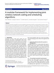
Figure 2 shows how the different generations ( g 0 , g1 ) within a mixing set of size two (m=2) differs by the probability of successful delivery. The first generation ( g 0 ) has a higher probability of successful delivery; since it is protected by the succeeding generation that has higher position index ( g 1 ).The second generation ( g 1 ) is the last generation in the mixing set. Figure 3 shows how the different generations ( g 0 , g1 , g 2 ) within a mixing set of size three (m=3) differs by the probability of successful delivery. The first generation ( g 0 ) has the highest probability of successful delivery; since it is protected by the two succeeding generations that have higher position indices ( g 1 , g 2 ).The second generation ( g 1 ) has higher probability of successful delivery than the third generation ( g 2 ) ( g1 is protected by g 2 which is the last generation in the mixing set). Figure 5 compares the average probability of generation successful delivery for mixing sets of sizes one, two and three (m=1, 2, 3). For a mixing set of size m, the probability of successful delivery is averaged over all mixing set generations. This figure shows that generally, by increasing the size of a mixing set MGM achieves an improvement in the probability of successful delivery. Figure 8 compares the probability of successful delivery for the last generations of mixing sets of sizes one, two and three (m=1, 2, 3). All these generations are last generations in there mixing sets; they are not protected by any other generations. These generations achieve close probabilities of successful delivery. This means that although MGM enhances the reliability of delivering generations of lower position indices, it does not degrade the reliability of delivering generations of higher position indices. For mixing sets of sizes two and three (m=2, 3) the last generation in these mixing sets achieves a decodable rate that is close to the case of the single
196
JOURNAL OF COMMUNICATIONS, VOL. 7, NO. 3, MARCH 2012
1
Probability of successful delivery
Probability of successful delivery
1
0.9
0.8
0.7
0.6
0.5 m=2 g0 m=2 g1 0.4
0
0.01
0.02
0.03
0.04
0.05
0.06
0.07
0.08
0.09
0.9
0.8
0.7
0.6
0.5
0.4
0.1
m=3 g0 m=3 g1 m=3 g2 0
0.01
0.02
Probability of packet loss
Figure 2: Probability of successful delivery for the two generations of a mixing set of size two (m=2). k=50, R=0.1.
0.05
0.06
0.07
0.08
0.09
0.1
1
Probability of successful delivery
Avg. Probability of generation delivery
0.04
Figure 3: Probability of successful delivery for the three generations of a mixing set of size three (m=3). k=50, R=0.1.
1 0.95 0.9 0.85 0.8 0.75 0.7 0.65 0.6 m=1 m=2 m=3
0.55 0.5
0.03
Probability of packet loss
0
0.01
0.02
0.03
0.04
0.05
0.06
0.07
0.08
0.09
0.1
Probability of packet loss
Figure 4: Average probability of successful delivery of generations in mixing sets of different sizes (m=1, 2, 3). k=50, R=0.1.
generation of mixing set of size one (m=1), which is the case of generation based network coding (no multigeneration mixing). IV.
SVC STRUCTURE
By using scalable video coding, video is encoded in layers a base layer and one or more enhancement layers. Video layers support the decoding of video in varying reconstruction quality. Higher video layers enhance the video of base layer. Enhancement is in terms of temporal resolution, spatial resolution, and fidelity. Scalable video stream consists of sub-streams that allow the decoding of video with a reconstruction quality that depends on the decoded sub-streams. From received substreams video can be recovered in different frame rates (temporal scalability), picture size (spatial scalability), and quality (fidelity). Supporting video recovery from received sub-streams has many benefits in a video communication system, this appears in a heterogeneous environment of a multicast scenario where a set of receivers request the same video content with different frame rate, size and quality. With SVC video is encoded once with sub-streams from which the receivers can decode video with requested quality. With SVC video there is dependency among coded video frames. Intra and inter layer video frames dependencies are among frames of the same layer or different layers respectively. The loss of a video frame can cause the © 2012 ACADEMY PUBLISHER
0.9
0.8
0.7
0.6
0.5
0.4
m=1 g0 m=2 g1 m=3 g2 0
0.01
0.02
0.03
0.04
0.05
0.06
0.07
0.08
0.09
0.1
Probability of packet loss
Figure 5: Probability of successful delivery for the last generations in mixing sets with sizes (m=1, 2, 3). k=50, R=0.1.
inability to decode other video frames in the same layer or among the different layers. With SVC the coded video stream is organized in NAL (Network Abstraction Layers) units. A NAL unit consists of a header and a payload. The header is one byte that specifies the type of payload of the NAL unit. Each NAL unit is identified by a tuple (D, T, Q). (D, T, Q) tuple specifies the Dependency ID (D), Temporal ID (T) and Quality ID (Q) of the NAL unit [10, 12]. NAL units identified by (0, *, 0) constitute the base layer of the video stream. * represents all possible levels of temporal resolution. NAL units of the base layer are the most important since they are referenced by NAL units of other video layers and they don’t reference any other layers. Figure 6 shows the dependency among NAL units of the different video layers. Spatial, temporal and SNR resolutions increase in the arrow direction. The loss of one NAL unit will cause the inability to
Figure 6: NAL units dependency among different video layers.
JOURNAL OF COMMUNICATIONS, VOL. 7, NO. 3, MARCH 2012
L
L
L
197
L
L M0
M1
L
L
L
L
L
L
L
L
M h −1
L
Figure 7: Non-scalable video packets grouped in generations for network encoding. Mixing set size is one (m=1), this is the case of generation based network coding.
L M1
M0
M ⎡h / 2 ⎤
Figure 8: Scalable video of two layers. Packets of each layer are grouped in generations that have the same position index in consecutive mixing sets. Mixing set size is two (m=2). L
L
L
L
L
L
L
L
L
L
L
L
L L L M0
M1
M ⎡h / 3 ⎤ Figure 9: Scalable video of three layers. Packets of one layer each grouped in generations that have the same position index in consecutive mixing sets. Mixing set size is one (m=3).
decode other NAL units. For example a NAL unit with (D, T, Q) = (1, 1, 0) cannot be decoded due to its dependency on NAL unit (D, T, Q) = (0, 1, 0) that was lost or not decoded. This means a NAL unit that is either lost or not decoded (due to its dependency on a nondecodable NAL unit) will spread to have more NAL units un-decodable. Due to the importance of lower layers to decode higher video layers, it will be of high advantage to prioritize the communication in a way that provides higher levels of reliable communication to lower video layers. This is the goal of applying MGM on scalable video; enhancing the reliability of communicating lower video layers without sacrificing the reliability of communicating higher layers. Next, we will discuss how to apply MGM network coding on video contents. V.
MGM FOR SCALABLE AND NONSCALABLE VIDEO
In packet loss networks, video is communicated in packets. NAL units are packettized in packets of limitted size. To apply practical network coding on video, video packets are grouped in generations. Hence a generation is a consecutive sequence of video packets. To apply multigeneration mixing, video generations are mapped to mixing sets. Hence a mixing set is a consecutive sequence of generations. Multi-generation mixing is applied by mapping video generations to mixing sets of size equals the number of video layers. We will focus on three scenarios. The first is non-scalable video with generation based network coding which is MGM with mixing set size one (m=1). The second scenario is © 2012 ACADEMY PUBLISHER
scalable video of two layers where MGM has mixing set size two (m=2). The third scenario is scalable video of three layers where MGM has mixing set size three (m=3). In Figures 7, 8 and 9, gx is the generation with index x. Py is the packet with index y. For the scenario of non-scalable video, video packets are grouped in generations that are mapped to mixing sets where the size of mixing set is one (m=1). In this case there is no inter-generation mixing and hence this is the case of traditional generation based network coding. Figure 7 shows the grouping of non-scalable video packets in generations that constitute mixing sets of size one. On the other hand, for the scenario of scalable video of two layers, video generations are mapped to mixing sets of size two (m=2). The first generation in consecutive mixing sets (generations with position index zero) consist of packets of video base layer. Second generation in consecutive mixing sets (generations with position index one) consist of packets of first enhancement video layer. In this case packets of base layer (first generations in consecutive mixing sets) are provided with higher level of reliable communication than packets of enhancement layer (second generations in consecutive mixing sets). This is because of encoding first mixing set generation in the second which allows the collective decoding of first mixing set generations as was explained previously. Figure 8 shows the grouping of video packets in generations that constiute mixing sets of size two. For the case of scalable video of three layers, video generations are mapped to mixing sets of size three (m=3). Generations with position index zero in consecutive mixing sets consist of video packets of base
198
JOURNAL OF COMMUNICATIONS, VOL. 7, NO. 3, MARCH 2012
layer. Generations with position index one in consecutive mixing sets consist of video packets of first enhancement layer. Generations with position index two in consecutive mixing sets consist of video packets of second enhancement layer. Figure 9 shows the grouping of video packets in generations that constiute mixing sets of size three. Next, we evaluate video network coding using extensive simulations. VI.
mixing with mixing set size two. m=3 is the case of scalable video of three layers and multi-generation mixing with mixing set size three.
PERFORMANCE EVALUATION
In this Section we evaluate the performance of practical network coding in video networks and with extensive simulations. Foreman video sequence of 300 video frames is encoded in one, two and three CGS layers so that a particular bit rate is targeted for each layer. In the scenario of single layer video (non-scalable) the target bit rate is 300Kbps. For the scenario of video of two layers, each layer is encoded with a target bit rate of 150 Kbps. And finally for the scenario of three video layers each layer is encoded with a target bit rate of 100 Kbps. Each layer is encoded with five temporal levels with 1.875, 3.75, 7.7, 15 and 30 fps Table 2 summarizes the stream layers bit rates and overall PSNR. Video sequence is encoded, decoded packetized and evaluated using JSVM 9.4 [13]. The packetized video streams are communicated using a round based network simulator that was developed for the purpose of evaluating practical network coding (Multi-generation mixing and traditional generation based network coding which is a special case of MGM). For the network topology, 400 nodes are distributed randomly in an area of 20×20. In each 1×1 unit area there is a randomly positioned node that can communicate directly with all nodes within a radius of 1.5. The network is of broadcast nature. At each round of simulation, only one node transmits within the transmission radius. Receiving nodes in a particular round are candidate senders in the following rounds. senders in the following round are selected so that there is no collision among their transmission. Source is a node at one corner of the topology and receiver is selected randomly to be close to the other corner. Each node transmits an encoded packet for every useful encoded packet received. A large number of simulations were done where performance was evaluated using different generation sizes. The quality of video at the selected receiver is evaluated at the same time we evaluated network coding decodable rates achieved by all nodes to show the improvement of achieving efficient spread of useful data across communicating nodes. In Figures 10, 11, and 12, m=1 is the case of single layer video and generation based network coding. m=2 is the case of scalable video of two layers and multi-generation
© 2012 ACADEMY PUBLISHER
Figure 10: PSNR of video communicated under network coding, m is mixing set size. m=1 is the case of generation based NC for non-scalable video. m=2 is MGM for scalable video of two layers. m=3 is MGM for scalable video of three layers.
Figure 11: Percent of unrecovered packets at receiver. , m is mixing set size. m=1 is the case of generation based NC for non-scalable video. m=2 is MGM for scalable video of two layers. m=3 is MGM for scalable video of three layers.
Figure 12: Ratio of network coding decodable packets received with generation based, and MGM m=2 to that received with MGM m=3, averaged over all nodes. This shows the overall network performance in decoding packets in comparison with MGM, m=3.
JOURNAL OF COMMUNICATIONS, VOL. 7, NO. 3, MARCH 2012
199
(a)
(b)
(c) Figure 13 :Five consecutive frames (78-82) of Foreman video sequence. (a) Generation based NC (MGM with m=1) applied on video sequence of single layer. (b) MGM with m=2 applied on video sequence of two layers. (c) MGM with m=3 applied on video sequence of three layers. Generation size k=10.
(a)
(b)
(c) Figure 14: Five consecutive frames (78-82) of Foreman video sequence. (a) Generation based NC (MGM with m=1) applied on video sequence of single layer. (b) MGM with m=2 applied on video sequence of two layers. (c) MGM with m=3 applied on video sequence of three layers. Generation size k=30.
PSNR values in Figure 10 are relative to those in Table 2. More precisely, for single layer video, PSNR values of PSNR in Figure 10 are relative to the maximum PSNR value of 34.5 (PSNR for single layer video). For scalable video of two layers, PSNR values in the figure are relative to the maximum PSNR value of 32.9 (PSNR for video of two layers). For scalable video of three layers, PSNR values in the figure are relative to the maximum PSNR value of 30.7 (PSNR for video of three layers). The goal is to show the ability of network coding in supporting the recovery of maximum video quality at receiver node for each of the three scenarios. For the selected receiver Figure 10 shows the PSNR of recovered video for the three scenarios of Figures 7, 8, and 9. When MGM is applied to scalable video of three layers (m=3) almost full video quality is achieved at Table 2: Bit rates and Y-PSNR for 300 video frames, SVC Foreman sequence. Number of Video Layers Single layer Two Layers Three Layers
Layer1 305.3 145.96 95.59
Bit Rate (Kbps) Layer 2 Layer 3 301.07 198.28 295.91
© 2012 ACADEMY PUBLISHER
Y-PSNR 34.5 32.9 30.7
receiver. It is higher than scalable video of two layers. For the scenario of non-scalable video we notice a poor quality of recovered video. This is due to the expensive losses of generation based network coding (explained previously). Figure 11 shows the percent of unrecovered packets at receiver for the three scenarios. Results shown in Figure 11 lead to the PSNR values shown in Figure 10, and follow the same justification. As seen in Figure 11 the cases of m=3 and m=2 looks similar to the cases of m=3 and m=2 of Figure 10. The case of m=1 in Figure 11 differs from that in Figure 10. In Figure 11 and for m=1, the increase in the percent of unrecovered packets is higher than the resulted decrease in PSNR shown in Figure 10. The reason for that is the deployment of video concealment technique upon the loss of video frames. Each lost frame is replaced by the last frame decoded correctly. This leads to the lowered effect of frame loss on the PSNR values of recovered video. In Figure 12 the percent of decoded packets of m=1 and m=2 relative to m=3 is evaluated. The percent of decoded packets is evaluated over all topology nodes for different
JOURNAL OF COMMUNICATIONS, VOL. 7, NO. 3, MARCH 2012
1
1
0.9
0.9
0.8
0.8
0.7
0.7
0.6
0.6
PSNR
PSNR
200
0.5
0.5
0.4
0.4
0.3
0.3
0.2
0.2 G based MGM, m=2
0.1 0 10
15
20
25
30
35
40
45
G based MGM, m=3
0.1 0 10
50
15
20
Generation size
G based MGM m=2
0.5
0.4
0.3
0.2
0.1
0 10
15
20
25
30
35
40
45
50
Generation size
Figure 17: Percent of unrecovered packets at the selected receiver. With MGM m=2 an improved decodable rate is achieved.
generation sizes. This gives a clear idea about the improvements achieved by multi-generation mixing in increasing the spread of useful packets among network nodes. As shown in the figure for MGM with m=2, over 90% of MGM, m=3 decodable rate is achieved. On the other hand with Generation based network coding (m=1) the decodable rate is between 40% - 75% of that for MGM with m=3. In Figures 13 and 14 the visual effect of loss on the recovered frames of Foreman video sequence is shown. In both figures (a) is for generation based network coding applied on video encoded in a single layer, (b) is for MGM with m=2 applied on video encoded in two layers, and (c) is for MGM with m=3 applied on video encoded in three layers. In Figure 13 losses incur distortion on the recovered pictures (frames of a). On the other hand we notice correct recovery of the pictures when MGM is applied on two and three layerd video (frames of b and c). In some scenarios MGM with m=2 losses degrade the quality of recovered video (as shown in Figures (10, 11, and 12). Figure 14 shows a scenario in which no frames are decoded with generation based network coding (frames of a). The five consecutive frames of (a) are copies of the last correctly decoded frame. Substiuting the last correctly received frame in the place of lost frames is the loss concealment approach used. At the same time as shown in (b) losses incur distortion on the recoverd frames when MGM with m=2 is applied. On the other © 2012 ACADEMY PUBLISHER
30
35
40
45
50
Figure 16: PSNR with multi-generation mixing and generation based for Foreman SVC sequence of three layers.
Percent of unrecovered packets
Percent of unrecovered packets
Figure 15: PSNR with multi-generation mixing and generation based for Foreman SVC sequence of two layers.
0.6
25
Generation size
0.6
G based MGM m=3
0.5
0.4
0.3
0.2
0.1
0 10
15
20
25
30
35
40
45
50
Generation size
Figure 18: Percent of unrecovered packets at the selected receiver. With MGM m=3 almost full decodable rate is achieved.
hand (c) shows the correct decoding of the five consecutive frames when MGM with m=3 is applied. Now we apply generation based network coding to scalable video and evaluate the quality of recovered video. More specifically, for video of two layers we apply generation based network coding (G-based) as well as MGM with mixing set size two (MGM, m=2). For video of three layers we apply generation based network coding (G-based) as well as MGM with mixing set size three (MGM, m=3). The goal here is to show that the improvement in video quality is mainly due to the deployment of MGM. Generation based network coding is applied on video encoded in two and three layers in Figures 15-18. Video packets are grouped into generations without distinguishing between the different video layers. In other words all video packets have the same level of reliable communication supported by generation based network coding. In Figures 15 and 16 MGM achieves major improvements in the quality of recovered video at receiver. In Figures 15 and 16 the improvement of MGM with m=2 (Figure 15) and m=3 (Figure 16) is over generation based network coding (G-based) applied on scalable video of two layers (Figure 15) and three layers (Figure 16). These improvements are achieved over the different generation sizes (generation size from 10 to 50). We note that MGM with m=3 (Figure 16) achieves almost full video quality at receiver. On the other hand
JOURNAL OF COMMUNICATIONS, VOL. 7, NO. 3, MARCH 2012
for MGM with m=2 (Figure 15) the quality of recovered video is degraded in some scenarios (generation size 30). This indicates that by increasing the size of mixing set reliable video delivery is assured. Hence the larger the mixing set the more reliable video communication. Figures 17 and 18 show the percent of unrecovered packets at receiver. With generation based NC (G-based), as the generation size increases there is an increase in the percent of unrecovered packets and hence a degradation in the quality of recovered video (as shown in Figures 15 and 16). The reason behind this is the increased cost of network coding losses as the generation size increases. On the other hand with MGM the percent of unrecovered packets is very low due to the supported inter-generation mixing.
201
[11]
[12]
[13]
[14]
P Chou, Y Wu, and K Jain, "Practical network coding," Allerton Conference on Communication, Control, and Computing, Monticello, IL, October 20, 2003. Jânio M. Monteiro, Carlos T. Calafate, and Mário S. Nunes, "Evaluation of the H.264 Scalable Video Coding in Error Prone IP Networks," IEEE TRANSACTIONS ON BROADCASTING, vol. 54, NO. 3, SEPTEMBER 2008. J. Vieron, M. Wien, H. Schwarz, “, "JSVM-9.4 Software, Joint Video Team (JVT) of ISO/IEC MPEG & ITU-T VCEG," 2007. S. Mirshokraie and M. HefeedaLive, “Peer-to-Peer Streaming with Scalable Video Coding and Network Coding", In Proc. of ACM Multimedia Systems (MMSys'10), pp. 123-132, Scottsdale, AZ, February 2010. Slides
VII. CONCLUSION In this paper network coding with multi-generation mixing was applied and evaluated in networks communicating video contents. Results showed major improvements in the quality of recovered video when multi-generation mixing is applied. The improvments in video quality is achieved due to the improved network coding decodable rates of multi-generation mixing. References [1]
[2]
[3]
[4]
[5]
[6]
[7] [8]
[9]
[10]
M. Halloush, and H. Radha, "Network Coding with Multi-generation Mixing: A Generalized Framework for Practical Network Coding," IEEE Transactions on Wireless Communications, vol. 10, pp. 466 - 473, December, 2010. R Ahlswede, N Cai, S Li, and R Yeung, "Network Information Flow," IEEE Transactions in Information Theory, July 2000. Abhinav Kamra, Vishal Misra, Jon Feldman, and Dan Rubenstein, "Growth codes: maximizing sensor network data persistence," SIGCOMM Comput. Commun. Rev., vol. 36, pp. 255-266 2006 C Gkantsidis, and P Rodriguez, "Network Coding for Large Scale Content Distribution," INFOCOM, Miami, 2005. S. Katti, D. Katabi, W. Hu Hariharan, and R. Medard, "The Importance of Being Opportunistic:Practical Network Coding for Wireless Environments," Allerton, 2005. C Fragouli, J Le Boudec, and J Widmer, "Network coding: an instant primer," Computer Communication Review, ACM SIGCOMM, Jan 2006. M. Halloush, and H. Radha, "Network Coding with Multi-generation Mixing," CISS, 2008. M. Halloush, and H. Radha, "Network Coding with Multi-generation Mixing: Analysis and Applications for Video Communication," ICC, 2008. "ISO/IEC 14496-10:2003 Information technology – Coding of audiovisual objects – Part 10: Advanced Video Coding." Heiko Schwarz, Detlev Marpe, and Thomas Wiegand, "Overview of the Scalable Video Coding Extension of the H.264/AVC Standard," IEEE Transactions on Circuits and Systems for Video Technology, vol. 17, NO. 9, SEPTEMBER 2007.
© 2012 ACADEMY PUBLISHER
Mohammed Halloush received the B.S. degree from Jordan University of Science and Technology, Irbid, Jordan in 2004, the M.S. and the Ph.D. degrees in Electrical Engineering from Michigan State University, East Lansing, MI, USA in 2005, 2009 respectively. Currently he is an Assistant professor in the department of Computer Engineering at Yarmouk University, Irbid Jordan. His research interests include network coding, multimedia communications, wireless communications and networking. Hayder Radha received the B.S. degree (with honors) from Michigan State University (MSU) in 1984, the M.S. degree from Purdue University, West Lafayette, IN, in 1986, and the Ph.M. and Ph.D. degrees from Columbia University, New York, in 1991 and 1993, respectively, all in electrical engineering. Currently, he is a Professor of electrical and computer engineering (ECE) at MSU, the associate Chair for Research and Graduate Studies of the ECE Department, and the Director of the Wireless and Video Communications Laboratory at MSU. His current research areas include wireless communications and networking, sensor networks, network coding, video coding, stochastic modeling of communication networks, and image and video processing. He has more than 100 peer-reviewed papers and 30 U.S. patents in these areas. Prof. Radha serves on the Editorial Board of IEEE Transactions on Multimedia and the Journal on Advances in Multimedia. He is an elected member of the IEEE Technical Committee on Multimedia Signal Processing and the IEEE Technical Committee on Image and Multidimensional Signal Processing (IMDSP). He is a recipient of the Bell Labs Distinguished Member of Technical Staff Award, the A&T Bell Labs Ambassador Award, the AT&T Circle of Excellence Award, the MSU College of Engineering Withrow Distinguished Scholar Award for outstanding contributions to engineering, and the Microsoft Research Content and Curriculum Award. He is also a recipient of National Science Foundation (NSF) Theoretical Foundation, Network Systems, and Cyber-Trust awards.