WeD01-01
Proceedings of the 2005 IEEE 9th International Conference on Rehabilitation Robotics June 28 - July 1, 2005, Chicago, IL, USA
A Framework of Interface Improvements for Designing New User Interfaces for the MANUS Robot Arm Hylke A. Tijsma, Freek Liefhebber, Just L. Herder Abstract— Users of the MANUS robot arm experience a high cognitive and physical load when performing activities of daily living with the arm. These high loads originate from user interface problems and limitations. To reduce these high loads the user interface of the MANUS needs to be improved. Because large differences exist between the residual capabilities of MANUS users, different user interfaces need to be developed. As a design aid, a framework with user interface improvements and new features was developed. With this framework several new user interfaces can be designed. Most interface features in the framework can be adjusted to the residual body functions of the users and thereby reduce the high loads that users experience.
T
I. INTRODUCTION
HE MANUS robot arm [1], which will be further referred to as ‘the arm’, was developed to aid physically disabled people that are confined to a wheelchair and have lost most of their hand and arm function due to a severe upper limb disability. The arm can partly compensate for this lost hand and arm function. The arm can literally provide ‘a helping hand’ to those disabled people and make them less dependent on aid [7] from others. The arm has seven degrees of freedom (DOFs) and is designed to be attached to the wheelchair of the user. In most cases the user controls the arm with the joystick of the wheelchair. Because the joystick is a 2 DOF input device and the arm has seven DOFs, the user must switch between the DOFs in order to manipulate with the arm in 3D space. This switching is done in a menu structure that is stored in the user interface of the arm. This so-called ‘mode switching’ between the DOFs, as well as other interface problems puts a high cognitive and physical load on the arm users. The result of these problems is that users get fatigued and stop using the arm. To reduce these problems the interface needs to be improved.
Manuscript received May 2, 2005. H. A. Tijsma was with the Department of Biomechanical Engineering of Delft Universtity of Technology as well as with the TNO Science & Industry during the research project (e-mail:
[email protected]) F. Liefhebber is with TNO Science & Industry, PO Box 155, 2600 AD Delft, The Netherlands (phone +31 15 2692267; fax +31 15 2692111; email:
[email protected]) J. L. Herder is Assistant Professor at the Department of Biomechanical Engineering, Faculty of Mechanical Engineering, Delft University of Technology (e-mail:
[email protected]).
0-7803-9003-2/05/$20.00 ©2005 IEEE
In this paper a framework of user interface improvements and new interface features is presented. This framework can be used as an aid with which several user interfaces can be designed. The framework was designed because every user is different and uses different residual body functions for the control of the user interface. From the framework we can choose different interface components that meet the wishes of the users. Most of the components can be adjusted to the residual body functions of the users. With the framework new user interface configurations were developed. We focused on interfaces that are controlled using a 2 DOF joystick as input device. By means of a case study, one interface that was designed with the aid of the framework will be discussed and evaluated. This paper concludes with a discussion into the functionality and limitations of the framework. For the comprehensiveness of the interface improvements and new features, and for the completeness of the framework, first the current (joystick controlled) user interface and interface problems will be discussed. Note that the manufacturer of the arm, Exact Dynamics, built several user interfaces, which are controlled using different input devices (e.g. keypad control) [1, 2, 3]. II. CURRENT USER INTERFACE The arm is currently controlled with the same 2 DOF joystick used for the control of the wheelchair. The speed of the arm is proportional to the joystick deflection. A dead zone of 30% of the total joystick deflection prevents the user from making unwanted arm movements at small unintentional joystick deflections. Currently only 1 DOF of the arm can be controlled simultaneously, even though it is possible to control 2 DOFs simultaneously with the wheelchair joystick. Because a maximum of only 2 movements can be controlled simultaneously, all movements are categorized in a hierarchical menu structure. The hierarchical menu structure consists of a main menu, from which 4 menus can be activated (in the up, down, left and right direction of the joystick). For the remainder of this paper these menus will be called the ‘control modes’. The control modes that can be selected are: --The drinking mode, in which a drinking movement can be mimicked. --The folding mode, in which the arm can be unfolded
235
before use, or folded after use. --Joint mode, in which all joints of the arm can be controlled separately. --Cartesian mode, in which the ‘position’ of the gripper of the arm is controlled using a Cartesian coordinate system. The ‘orientation’ of the gripper is controlled by rotations about the vertical world axis, and about the lateral and longitudinal gripper axes. In an activate control mode the user can manipulate with the arm by making joystick deflections at normal speed. In the drinking and folding mode the arm movements can be made directly. The Cartesian and Joint modes each have 4 submodes, in which the accompanying movements are categorized. If one of those submodes is activated, the user can make the arm movements stored in that submode. The user activates a control mode by making a normal joystick deflection in the direction of the desired control mode (in the up, down, left or right direction of the joystick). By giving a short flick with the joystick the user returns to a higher level in the menu structure and thereby deactivates the control mode. In figure 1, this method of activating and deactivating control modes is explained. In the remainder of this paper we call changing control modes ‘mode switching’. Note that, because short flicks are used for deactivating control modes, the user cannot slightly change the position or orientation of the arm by giving short flicks as this would lead to unwanted mode switches. Visual feedback of the activate control mode to the user is presented through a 5x7 LED display that is usually mounted on the worktable of the wheelchair. In this display a distinct symbol, which represents the active control mode, is displayed. In a previous study [4] the functionality of this user interface was investigated. Amongst the most important problems that emerged during this functionality study were: --The lack of ability to adjust the user interface to the wishes and residual body functions of the user;
Fig. 1. Cross-shaped menu structure: Activating and deactivating control modes (grey is an optional menu).
--User interface only allows simultaneous control of 1 DOF instead of 2. --Hierarchical menu structure difficult to understand.
--Too little feedback of current control mode. --Unintentional mode switching. --Gripper orientation difficult to understand. --Users have difficulties performing accurate arm movements. --The arm speed too low. These problems cause the high cognitive and physical loads that users experience. Because of these high loads, the users get fatigued and stop using the arm. Because every user is different, and uses different residual body capabilities for the control of the arm, it is of utmost importance that the interfaces are designed in such a way that they can be adjusted to these residual body capabilities of the users. Other design criteria that emerged from the study [4] and that were used during the design of the interface improvements and new interface features are: --The system must be usable in unstructured environments. --The system must be easy to operate using a low mental load. --The system must behave as expected by the user. --The system must simplify manipulation with the gripper. --In the new system the number of required mode switches and the time needed for performing a task must be reduced. III. FRAMEWORK OF INTERFACE IMPROVEMENTS AND NEW INTERFACE FEATURES The interface improvements and new features that will be presented in this section are categorized in a framework. A good interface should consist of one or more features of each topic of the framework. The topics of which the framework consists are: input device, speed profile, methods of mode switching, control modes, menu structures, graphic interface and the Set-Up menu. At the end of this section the framework (figure 6.) with the interface features and improvements is presented. A. Input Device The arm functionality can be improved by making it possible to control 2 DOFs simultaneously, making use of both DOFs of the joystick. Besides the joystick, additional input devices can be used for the control of the arm. Almost every user is capable of controlling a simple switch. Such an additional switch provides many possibilities to improve the control of the arm. Furthermore, for instance voice control can be used for mode switching and/or making arm movements. B. Speed-Profile During the functionality study we learned that users have problems performing accurate arm movements. The accuracy of the arm at low speeds can be improved by replacing the proportional joystick speed profile by quadratic and third order profiles.
236
In addition, we can make the dead zone and gain of the joystick adjustable to the wishes of the user. Also the arm speed is made adjustable. C. Mode Switching Using the conventional method of mode switching (discussed in ‘II. Current User Interface’), the user must always pass through the centre of the cross-shaped menu structure. Besides this, normal joystick deflections and fast joystick flicks are both necessary to change from one control mode to the other, which can be confusing. A more logical and intuitive way is to always use a fast flick for mode switching. This leads to the alternative methods of mode switching that are displayed in figures 2A and 2B. The idea behind this method is that the user gives a flick in the direction of the control mode he wishes to activate. By using this method of mode switching the user can go straight from one control mode to another by making a single flick. This method is less ambiguous and can save a substantial number of mode switches. Because every user has got different strength and residual hand and finger speed the fast flick time is made adjustable to the wishes of the user (in all joystick directions). Besides using the joystick to switch modes, it is also possible to use voice control. When using voice control, we are not bound by any menu structure at all; we can ‘command’ a control mode to become active. D. Control Modes Besides the Cartesian mode and joint mode, which are implemented in the current user interface of the arm, additional control modes, like pilot mode and cylindrical mode can be introduced [2, 3, 4]. 1) Pilot Mode This is a control mode that is based on the orientation of the gripper frame. The gripper displacements are defined along the vertical, lateral and longitudinal gripper axes; the orientation is defined by three rotations (yaw, pitch and roll) about these gripper axes. In this control mode, the user must first orient the gripper towards the object of interest, after this the gripper can be steered towards this object by moving forward.
Fig. 2. Using fast flicks to switch mode. A = new method of mode switching applied on current menu structure. B = another version of a menu structure.
2) Cylindrical Mode This is another possibility; here the coordinate system is based on cylindrical coordinates, with the arm base used as a reference. 3) Position Mode Besides these control modes that are based on speed, we can also introduce control modes based on positions. Using such a control mode the user can for example get the gripper of the arm to the worktable of the wheelchair by giving the proper position commands. 4) Collaborative Control Mode A small camera can be mounted on the gripper of the arm; the images coming from this camera can be used to control the arm. This can be done manually or automatically. By looking at the camera images displayed in a graphic interface the user can control the arm. Such a new control method could expand the functionality of the arm, new tasks are made possible; for example inspection tasks, or tasks like getting objects from the floor or from a high shelf. These tasks are currently not possible because the user cannot see objects at these locations; most users are physically so weak that their heads are tied to a head support that is attached to the wheelchair to prevent them from falling over; the result is that the users can only look forward. We can also use the images coming from the grippermounted camera to let a computer system control some of the DOFs of the arm automatically. The automatic control on the basis of camera images is known as ‘visual servoing’. If we distribute the to be controlled DOFs between this computer system and the user we use a technique known as ‘collaborative control’ [5, 6]. In figure 3, a control scheme of the arm in which this collaborative controller is implemented is shown. For controlling even more DOFs with the computer system we can mount a distance sensor on the gripper. With this distance sensor the distance to the object of interest can be determined and controlled (this is known as ‘distance servoing’). This distance servoing can also be incorporated in the collaborative controller. The collaborative controller that can be implemented in the user interface of the arm, as shown in figure 3, works in three successive phases: 1. The selection of the object of interest. This can be done using several different procedures: --The user can pinpoint the location of the object of interest by moving a crosshair over the camera image using the joystick. By pressing a switch, giving a fast flick with the joystick or a voice command, the object of interest can be selected. --In the graphic interface a grid can be projected over the camera image. The user selects the segment of the grid in which the object of interest is situated, this segment is magnified and a new grid is projected over the magnified area. This procedure can be repeated several times until only the object of interest is visible in the camera image. Selecting
237
Fig. 3. Arm control scheme with collaborative controller: the DOFs are divided between the user and the computer system.
Fig. 4. Centre of rotation of the gripper: A = conventional, B = Adjusted.
the segments of the grids can be done by giving voice commands. --We can also use an object recognition algorithm to label all objects visible in the camera image. The user simply selects the proper object by giving a voice command. 2. Orienting (and moving) the gripper towards the object of interest (this is dependent on which DOFs are controlled automatically). 3. Turning off of the collaborative controller. This can be done automatically if certain criteria are satisfied, or if the user gives the command to turn off the controller.
welcome if more control modes are introduced. If we decide to implement the collaborative controller we have to make the camera images visible. If we use a TFT display the camera images can be displayed and the menu structure can be visualized
E. Menu Structure In new user interfaces it is likely that the functionality of the arm is expanded with new (additional) control modes and menus. Because the current hierarchical cross-shaped menu structure only allows for four sub-menus, different menu structures need to be designed in which more control modes can be accommodated. Menu structures where this is possible are menu structures in which all menus are aligned in rows or columns. In figure 5, an example of such a menu structure is displayed. By making a fast flick in the appropriate direction (in this case to the left or to the right) the user can scroll through all available control modes and menus. By making a flick in another appropriate direction (in this case downwards), the user activates the control mode. The menu structures in which the menus are aligned can be combined with cross-shaped menu structures. Such combinations can offer advantages: We have a menu structure in which the user scrolls through the main control modes as indicated in figure 5, and he changes from one submode to another using the cross-shaped structure displayed in figure 2B. In this way the user can switch from one submode to another by making one flick, and he can also scroll though numerous control modes without a difficult to understand hierarchical menu structure.
G. The Set-Up Menu Most interface features that were discussed above can be tuned to the wishes of the user with the aid of an occupational therapist, examples of such adjustable features are: the fast flick time, the joystick gain, the joystick dead zone and the speed profile. For other features it is wise to implement a Set-Up menu in the user interface in which the user can adjust the interface to the situation. Examples of possible parameters that can be adjusted are: the arm speed, the number of DOFs controlled by the collaborative controller and the centre of rotation of the gripper, that will be discussed next. 1) Centre of Rotation of the Gripper Currently the orientation of the gripper is defined by three angles about the vertical world axis and the lateral and longitudinal gripper axes. The centre of rotation of the gripper lies in the crossing of the three axes (in figure 4A, the coordinate system and rotation angles of this centre of rotation are displayed). We can alter this centre of rotation of the gripper by defining a ‘virtual’ joint along the longitudinal gripper axis. For example, by defining the virtual joint in the centre of the fingertips of the gripper we can rotate about these fingertips. This makes new gripper movements possible. By rotating about the vertical axis of this new centre of rotation a screw bottle can be opened. By making a rotation about the lateral axis a bottle of beer can be uncorked. This centre of rotation is displayed in figure 4B. Such alternative centres of rotation may possibly simplify arm movements and/or the difficult to understand gripper orientation.
F. Graphic Display From the functionality study we have learned that sometimes the users get lost in the menu structure. By providing more visual feedback of the menu structure we can reduce this problem. Providing more feedback is also
H. Summary of the Framework The above discussed interface improvements and new interface features provide possibilities for the design of different new user interfaces and are added in the framework. Many of the interface improvements and new features in this
238
Fig. 5. Menu structure in which the main control modes are aligned in a row.
framework can be adjusted to the residual capabilities of the users. In figure 6 the framework is presented. This framework has at least three applications. It can be used by interface designers as an aid for the design of new user interfaces and new interface features. It can help designers check if their interfaces are complete and what topics and features are necessary to build a good user interface. Furthermore, occupational therapists can use this framework for adapting user interfaces to the wishes and residual capabilities of users. The framework also serves as an overview of the possible interface features. By selecting different features from each topic of this framework different user interfaces can be designed or can be adjusted. The bold interface features in the table represent the current user interface. The grey cells in the framework represent interface features that were used for the user interface that is described in the next section. Not all combinations of the features can be combined into new user interfaces. For instance, some interface features represented in the framework are related to the input device: e.g. if the joystick is not chosen as input device, the speed profiles and some methods of mode switching cannot be chosen. The framework from figure 6 can be easily expanded with new features (such as new input devices). When this is done, the functionality of this framework expands and can be used for the design of interfaces for even more different arm users. IV. CASE STUDY The largest group of arm users are still capable of properly moving their wheelchair joystick in all joystick directions. In this case study, we will explain an interface design for this group of arm users, making use of the proposed framework. For controlling this user interface the wheelchair joystick will be used. The functionality of the arm is improved by making it possible to simultaneously control two DOFs with the joystick. A third order speed profile is chosen to make more accurate arm movements possible. The dead zone and the gain of the joystick can be adjusted in four separate joystick directions according to the wishes of each user. A switch is added with which a collaborative controller will be controlled. For switching between control modes, we use the method of mode switching using ‘fast flicks’ (see figure 2B). The fast flick time is adjustable to the wishes of each user.
Fig. 6. Framework of possible interface features: Bold terms denote current interface, grey cells denote interface discussed in the case study.
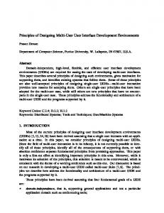
In this user interface the user can switch between the following menus/control modes: joint mode, pilot mode, Cartesian mode, position mode, folding mode, drink mode and the Set-up menu. Besides the above-mentioned control modes, a collaborative controller and a control switch are implemented. By pressing the switch the selection procedure of the collaborative controller is activated. The location of the object of interest can be pinpointed on the graphic display using the joystick. Pressing the switch again actually activates the controller (i.e. the collaborative controller starts to generate control signals). The controller can be deactivated any time by again pressing the switch. The number of DOFs that are controlled automatically can be adjusted to the wishes of the user. The collaborative controller works separately from the menu structure; in this way it can always be activated and does not increase the size of the menu structure. In the Set-up menu, the user can change the centre of rotation of the gripper from the conventional (wrist) joint to the virtual joint that is located between the gripper fingers. The user can change the maximum speed of the arm in 50% or 100% of the maximum arm speed. This 100% maximum speed can moreover be adjusted according to the wishes of each user. The graphical user interface (see figure 8) is displayed on a 7-inch widescreen TFT display. In this user interface, we aligned all the main control modes/menus in a row. This row is displayed in the upper part of the figure. Giving fast flicks to the left or to the right allows the user to scroll through these control modes/menus. A control mode can be activated by giving a fast flick downwards. If the control mode is active, the sub modes of this control mode will be displayed to the left of the camera image of the gripper-mounted
239
camera. The user can change from the one sub mode to the other by giving a fast flick in the appropriate direction. A control mode is deactivated by giving one or two flicks upwards (depending on the activated submode). Before each individual user gets to work with the new interface, the dead zone and gain of the joystick, the fast flick time and the maximum arm speed is adjusted to the wishes of the user by the interface designer or an occupational therapist. V. EVALUATION CASE STUDY When we perform an ex ante evaluation of the interface discussed in the case study, we see that the user problems, which were briefly discussed in this paper, can largely be solved. In the user interface it is now made possible to control 2 DOFs simultaneously. More accurate arm movements can be made with the quadratic and third order speed profiles. Besides this, the arm speed is made adjustable to the wishes of the user. It is likely that the number of unintentional mode switches is reduced because we use a less ambiguous method (fast flicks) for mode switching. Another advantage is that the fast flick time is made adjustable to the wishes of the user. By adding pilot mode, the collaborative controller and the possibility to change the centre of rotation of the gripper, some arm movements are made more understandable and thereby also the functionality of the arm is extended. The difficult to understand hierarchical menu structure is replaced by an improved, easier to understand and more intuitive menu structure. The feedback to the user is increased using the TFT display in which the whole menu structure is displayed. In the companion paper “Evaluation of new user interface features for the MANUS robot arm” [8], this interface will extensively evaluated.
the users; this makes the new interfaces designed with the framework easier to operate. There are however limitations to the adjustability of the interface parameters. Some users have such specific residual capabilities for which no suitable interface features were developed. The first step in the design of a good interface is always the selection of the proper input device. This is because the input device is of major importance for the control of many other components in the interface. Designing a good user interface for users that cannot control a joystick anymore begins with the investigation of what kinds of input devices these users can still control. The framework can be used to check for which topics new interface features, adjusted to that input device, need to be designed. A big problem arises if users are physically so weak that they have difficulties controlling any input device in general. For these users we have to try to find other solutions so these users can also benefit from the arm. VII. CONCLUSION The interfaces designed with the framework presented in this paper solve part of the problems that emerged during the functionality study. With the current framework we can design a number of different user interfaces that are easier to operate than the current interface. The current framework is easily expandable and can be used for different purposes. The framework provides a good overview of the current possible interface features. User interface designers can use the framework as an aid during the design of new interfaces and new interface features. Occupational therapists can use the framework to adapt an existing interface to specific user wishes. REFERENCES
VI. DISCUSSION
[1] [2]
A considerable improvement is that most interface features in the framework can be adjusted to the wishes of
[3]
[4]
[5]
[6]
[7] [8]
Fig. 7. Screenshot of the graphical arm user interface.
240
Exact-Dynamics: http://www.exactdynamics.nl/english/index.html Kwee, H.H. et al., Integrated control of manus manipulator and wheelchair enhanced by environmental docking. Robotica, 1998, Vol. 16, p. 491-498 Kwee H.H., et al. Adapting the control of the MANUS manipulator for persons with cerebral palsy: An exploratory study. Technology and Disability 2002 Vol. 14, p. 31–42 Tijsma, H.A. et al., Manus, ‘a helping hand’ designing a new intuitive user interface for the manus robot arm, masters thesis A-1000, Delft University of technology, 2004, p. 12-19 Versluis A.H.G. et al., Enhancing the usability of the MANUS manipulator by using visual servoing. Proceedings of the International Conference On Rehabilitation Robotics (ICORR) 2003 Versluis A.H.G, et al., Collaborative Control Aspects for Rehabilitation Robots. Proceedings 2nd Cambridge Workshop on Universal Access and Assistive Technology (CWUAAT) 2004 de Witte P, et al. MANUS: Een helpende hand. iRV 2000 (translated from Dutch: A helping hand) Tijsma, H.A. et al., Evaluation of new user interface features for the MANUS robot arm. Submitted to International Conference On Rehabilitation Robotics (ICCOR) 2005