2 ML and Concurrent ML. Figure 1 shows the software development flowchart for the methodology. Conventional parallel development in- volves taking a serial ...
A FUNCTIONAL METHODOLOGY FOR PARALLEL IMAGE PROCESSING DEVELOPMENT
D J Johnston, M Fleury, A C Downton University of Essex, UK
1 INTRODUCTION Parallel Image Processing has been a topic of interest for many years, but has not yet delivered a design methodology which can maintain portability across rapidly changing parallel implementation technologies. The two hurdles to be overcome are the difficulties of re-arranging application code into a parallel form and the lack of a general and universally supported parallel machine model. This paper addresses these problems using a functional language transformation, illustrated in the context of a particular application. We show that the overhead introduced by the transformation is relatively small, but the benefit derived is substantial, since the functional programming discipline enforces an implementation-independent definition of core parallel requirements, which can then be mapped onto a broad set of parallel architectures, ranging from shared and distributed memory conventional multiprocessors to direct hardware implementations constructed using silicon compilers and FPGA technology.
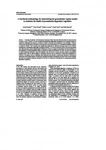
2 ML and Concurrent ML Figure 1 shows the software development flowchart for the methodology. Conventional parallel in������ development volves taking a serial application ( ) and converting ������� ) which interfaces with a parallel it into a form (
� � � � � � harness ( : software which controls the runtime execution on a parallel architecture. This is a difficult process because the harness is normally inflexible thirdparty software which was abstracted with an imperative language mind-set. The proposed methodology takes a sequential application in the functional � � ); portsexpressed ���� �lan ) guage ML ( this to a parallel form ( in the language CML (this is ML with a parallel library designed by Reppy [4] based on the CSP model due to Hoare [1]); and then finally into both a par�� �abstracts
) and a this allel harness��in� CML ( sequential applica � ). tion in ML ( Although the overall development methodology may seem more complex, the application only � � �developer ���� �� ,iswhich asked to perform the transform by careful choice of the parallel abstractions is actually a very minimal change, unlike the equivalent conventional parallelisation in C++. All other transformations only need to be implemented once as part of developing the methodology. Ultimately, the user still has to translate
SPECIFICATION implementation
A
ML
translation parallelisation parallelisation
A’
A
CML
C++
abstraction
parallelisation
abstraction
H
CML
A’’
ML
translation
H
A’
C++
C++
translation
system transformation
A
L
H
L
application in language L
user transformation third party transformation
harness in language L
Figure 1. intermediate ML development ML software to C++ (this stage has not yet been automated, though previous work shows it is possible [5]), and this is done at the end of the development cycle. Translating at the earlier stage is pure sequential ML prototyping, though it is then also possible to parallelise within C++ using the proposed method by interfacing to the harness C++ API which is the same as the ML �� API. ��� For C++ coders, the method introduces a new module, but one providing flexibility and composability, deriving from the functional way it was conceived.
3 SIMPLE EXAMPLE Before introducing the application under discussion, it is useful to illustrate the functional style by the tractable and complete expression of a convolution algorithm. fun convolve2D (src, filter) = let (* get sizes of src image and filter val (sh,sw) = dimensions src; val (fh,fw) = dimensions filter;
*)
(* produces a single element of convolution matrix *) fun single_convolve (r0,c0) = let (* multiply corresponding filter and src elements *) (* offset into src is (r0,c0) *) val product = tabulate (fh,fw,fn(i,j) => sub(src,i+r0,j+c0) * sub(filter,i,j) ); in (* add together elements of product matrix *) (* reduction/fold operation is add *) fold ( fn (a,b) => a + b ) 0.0 product; end; in (* result is size of src minus size of filter *) tabulate ( (sh-fh)+1, (sw-fw)+1, single_convolve ); end;
camera digitising
i 256
256−level image
filtering
i3
3−level image
ir
region image
painting
t
region table (geometry)
g
region adjacency graph (topology)
Figure 3.
������
target location position determination
Figure 2. serial image processing In (C)ML, functions can be manipulated with the facility of data, so a result matrix is specified solely by its dimensions and a rule (or function) to produce each element. These are passed to a higher-order function tabulate. Traditionally the low execution performance of ML has relegated it from the development of “real” applications. However, with advances in software and hardware even compute intensive operations, such as this convolution, are now becoming practical under ML.
4 PAINTER’S ALGORITHM Position determination within an Augmented Reality system is a typical combined image processing and computer vision application [2]. Targets are identified within a video stream, by decomposing each frame into regions using the “Painter’s Algorithm”. This does not fit comfortably into existing parallel paradigms and so presents a realistic challenge for parallel image processing. The target identification image processing pipeline is shown in Figure 2. The captured 256-level greyscale image (Figure 3) is filtered to a 3-level greyscale image (Figure 4) to enhance the visibility of regions within black and white targets. Each distinct connected region within the 3-level greyscale image is then painted a unique colour (Figure 5). Indeed this colouring algorithm, the “Painter’s Algorithm”, is the means by which distinct regions are computed. Eventually this image information is distilled into a Region Adjacency Graph (RAG) which holds topological information of region connectivity and a region table which contains geometric information, such as the centroid, for each region in the graph. The RAG and table are used to identify the targets. Then from the known locations of these targets in the real world, it is possible to work out the position of the camera (for fixed targets) or target-tagged objects
Figure 4.
��
(for fixed camera). The super-position of a wireframe cube in Figure 3 indicates that the location of the cube has been successful. Consider the conceptual parallelisation in Figure 6. For simplicity, it is assumed that the processing is split geometrically into just two parts: a right-hand and a lefthand half image. As the corresponding 3-level greyscale images are produced by adaptive spatial filtering, edges of the input 256-level greyscale half-images have to be swapped at their join. The Painter’s Algorithm can be run independently on each half to produce the conventional serial output of a table and graph. (The parallelisation of either the target detection or subsequent position determination is not addressed. However, these only constitute around 2% of the overall processing time.)
How are the right and left RAGs (� and � respectively) and the right and left tables (� and � respectively) joined? This requires further information describing the region connectivity across the split, which is derived from the along each
line of pixels
and
side of the split
��� images. from the ��� , ��� , ���
To appreciate the problem consider the painted image and the corresponding two painted half-images in Figure 7. It can be seen that the painting (or region numbering) occurs scanning top-left to bottom-right. We cannot put the two painted half images together and get automatic agreement on region numbering. Instances of all possible cases occur: the same region numbered differently � � and ��� � wrong different numbered the same ��� and � regions � � wrong the same region numbered the same � � and � � � coincidentally consistent Figure 5. �
different regions numbered differently � � and � � � coincidentally consistent
i 256 ( i 256 )L
( i 256 )R
swap edges
( i 3)L
( i 3)R
( i r)L
( i r)R
gL
tL
gR
tR gm
tm
type serial_input = image; type serial_output = graph * table; type serial_process = serial_input -> serial_output;
target location position determination
Figure 6. parallel image processing
1
The parallel algorithm to reconcile region numbering is similar to the serial Painter’s Algorithm. In fact, only the numbering in one half image has to be changed - and indeed only the pixels at the boundary of this half-image have to be physically repainted for the algorithm to work. Note that an image is not part of the original serial output, but partial images (edges) need to form part of the output of the parallel processing for edge-data accumulation. These are calculated anyhow (as intermediate results) so this is no great hardship. We can categorise the serial and parallel processing by their CML type signatures:
What further infrastructure is required to run the application in parallel? We require functions to split the input and combine the output:
3
2
4
5
type parallel_input = image; type parallel_output = graph * table * edge * edge; type parallel_process = parallel_input -> parallel_output;
type split_input = parallel_input -> parallel_input * parallel_input;
6
type combine_output = parallel_output * parallel_output -> parallel_output; 1
2 1
2 3
4
3
4
Figure 7. geometric subdivision of the Painter’s Algorithm
Splitting a geometric structure such as an image is sufficiently regular, that a function matching split input does not have to be supplied by the programmer. Interestingly, the final output from the parallel and serial implementations of the Painter’s Algorithm is different in general, but they will be equivalent up to a re-ordering. The remaining concern is how to swap the edge data for initial filtering? A compromise was reached that though this communication has still to be explicitly actioned by
2 1 4
1 2
1
1
3
1
2 1
3 1
2
2
3
1
4
1
2 1
2 5
1
3
4
1
1
2 1
3
2 1
4 2
1 3 5
Figure 8. two accumulation patterns the programmer, the fact that it is a communication is hidden. The programmer makes a system call of type window to bring in edge data from the associated subimages on other processors, creating an image which is bigger by the extent of a specified “halo”. type window = image * int -> image; (* the integer is the edge width being added *)
The functional version of the application is in a form which describes the inherent potential parallelism but makes no effort to exploit it in any way. In short, the application should be portable across a variety of parallel architectures and indeed generations of the same parallel architecture where conventionally a upgrade would mean a new tuning phase. This moves forward from existing approaches, such as that of Michaelson and Scaife [3] who prototyped image processing systems in sequential ML but ported to and parallelised with occam. Here the parallelisation forms such an integral part of the prototyping process, that it can be abstracted in a flexible functional manner and re-used composably.
6 CONCLUSION The use of a functional language has been demonstrated in the development of a parallel image processing application. The advantages are: quick prototyping and program transformation
In summary, an underlying harness is able to run the application in parallel providing the programmer supplies two function: one of type parallel process and the other of type combine output. If the programmer wants to slot the parallel code into the existing serial slot then the following trivial conversion routines are convenient:
fewer errors (from enforced type checking) reduced overall development time elegant encapsulation of parallelism The disadvantages are: manual translation from CML to C++ is required.
fun serial_input_to_parallel_input (i:serial_input) = (i:parallel_input);
absence of I/O libraries within CML.
fun parallel_output_to_serial_output ((g,t,e1,e2):parallel_output) = ((g,t):serial_output);
poor performance of CML relative to C++.
5 DISCUSSION The function with signature parallel process is little different to the serial code and it must use a function of type window. The latter is optional, though good practice, for the serial code. However, the function with signature combine output is new in conception and contains the tricky accumulate operation necessary for parallel operation. It would be almost impossible for a parallelising compiler to invent this algorithm, so there is an equitable separation of concerns. The programmer knows about the application and describes how objects should be split and combined: all this code is purely sequential and makes no mention of granularity or communication. The runtime system knows about the underlying parallel architecture but not the application, but can dynamically tune the division of work across processors to obtain optimum performance. On a processor grid, the final binary accumulation can be done in a variety of ways. For example, the two communication patterns in Figure 8 were both used - illustrating a particular instance of the decoupling of expression and implementation. The numbers show the ordering of phases within the accumulation.
It is possible to interface CML to C++ to take advantage of the facilities and speed of the latter language, without translating the whole of an application. Overall, a translation is essential if real-time image processing is required but with faster machines ML is now practical for image processing development.
References [1] C. A. R. Hoare. Communicating Sequential Processes. Prentice Hall, first edition, 1985. ASIN: 0131532715. [2] D. J. Johnston. Position Sensing and Augmented Reality. PhD thesis, University of Essex, 2002. [3] G. Michaelson and N. Scaife. Prototyping a parallel vision system in standard ML. Journal of Functional Programming, 5(3):345–382, 1995. [4] J. H. Reppy. Concurrent ML: Design, application and semantics. In Functional Programming, Concurrency, Simulation and Automated Reasoning, pages 165–198, 1993. [5] D. Tarditi, P. Lee, and A. Acharya. No assembly required: Compiling standard ML to C. ACM Letters on Programming Languages and Systems, 1(2):161–177, June 1992.