A SEMI-FORMAL METHODOLOGY FOR THE FUNCTIONAL VALIDATION OF AN INDUSTRIAL DSP SYSTEM Laurent Arditi and Gaël Clavé Texas Instruments. BP 5, Mail Stop 21 06270 Villeneuve Loubet. France
[email protected] [email protected]
ABSTRACT This paper describes a new methodology allowing to increase the efficiency of functional validation. The approach is based on a combination of simulation and formal techniques. It consists in first building formal models of digital hardware modules. The coverage of a test suite can then be accurately measured and new test cases are automatically generated to increase the coverage. This methodology has been applied during the development of a commercial DSP system. It has shown that, in spite of a very large test suite constituted of 300 Millions of simulation cycles, there was still a room for coverage improvement.
1. INTRODUCTION It is now recognized that the functional verification is the bottleneck of industrial design projects. Simulation of hand-written or randomly generated test cases is too time and resource consuming so that it usually provides a poor coverage, leading to many undiscovered bugs. Formal verification techniques are more exhaustive and powerful but they are difficult to use and do not apply to large designs. Therefore, there have been recent efforts in closing the gap between formal and simulation-based verification [8]. On the one hand, some projects have used formal verification to cover validation aspects which where not, or not enough, addressed by simulation [6]. For example, equivalence checking can prove a RTL design and a gatelevel description are equivalent. Model checking can prove temporal properties such as the absence of dead-lock or live-lock which is impossible by simulation. On the other hand, some projects have used formal techniques while still relying on simulation [10]. Formal tools are used to generate test cases which will then be validated by simulation. The advantage is that the number of test cases is usually small but their quality is good [11][2][9]. The work presented in this paper is part of this last approach. The key points are: • The methodology does not break the traditional development flow: It is transparent for designers and verification engineers. • Formal models of the modules to be verified are written in the formal language Esterel [3]. They are then compiled in C code which is integrated in a software simulator. • The software simulator is run on an initial test suite. The results and the models are analyzed by formal tools to get a coverage measure. • Test cases are automatically generated to increase the coverage. • The test cases developed by our methodology can be reused at all the phases of the project flow, down to the test of the physical implementation of the chip. The methodology is generic since it may be applied to any digital hardware design. It has been adopted during the development of a commercial DSP system showing promising results.
Layout of the paper: the next Section presents the framework of our methodology. Section 3 details our coverage analysis while Section 4 shows how the new test cases are derived. We give some experimental results in Section 5, we compare our work to related ones and conclude in the last Section.
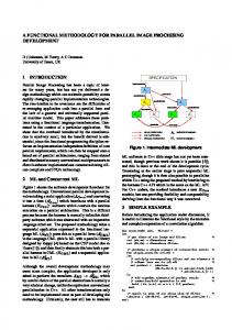
2. MODELS AND VERIFICATION 2.1 Software vs Hardware Verification The design we proposed our methodology for is a next-generation DSP. It consists of a DSP core (the CPU) and peripheral devices (memory controllers, DMA, bus controller, host processor interface,...). All the modules form a system-on-a-chip which is called a “Megacell”. Our verification effort is not only targeted at the CPU but also at the whole Megacell. Thus, we are doing system-level validation. The key-point of our verification methodology is the design of a software model of the DSP. That model is not an “instruction set simulator” of the CPU but it models the whole Megacell. Moreover, the software and hardware models are cycle and boundary accurate. That means both model outputs are equivalent at each cycle when run with the same input trace. The overall validation flow is shown on Figure 1 and detailed below. Specifications Software model (C-model)
signature check
Test suite
simulation and pattern extraction
Hardware model (VHDL-model)
mismatch detection
simulation
Figure 1. The Validation Flow
• • • •
•
The software model (C-model) is written in C/C++, following the system specifications. Parts of the model are also automatically generated. The hardware model (VHDL-model) is written in VHDL at the Register-Transfer Level. A test suite is developed. It contains automatically generated or hand-written test cases. They are binary or assembly language programs, including a mechanism of signature. Test cases are run on C-model. In case of signature failure, an analysis determines whether the cause is a bug in C-model, in the test case, in a bad understanding or the fuzziness of the specifications. When a test case produces a valid signature, input/output values are extracted from the simulation on C-model. Inputs are then injected for the simulation of VHDL-model. Outputs generated by both models are compared.
2.2 Test Suite Coverage
3.1 Coverage Measure and Improvement
One can see that the correctness of VHDL-model (hence the final chip) relies on the one of C-model, which in turn relies on the pertinence of the test suite. We have developed about 60000 test cases, representing 330 Millions of simulation cycles. We have also simulated real-world applications representing Billions of cycles. However, it was not clear whether the test suite provided an acceptable coverage. Our contribution is to provide techniques and tools to (1) get a coverage criterion, (2) determine functional areas for which the coverage is not satisfactory, (3) automatically improve the coverage. These goals could only be achieved by using formal languages and tools. But breaking the project flow listed above would not have been accepted. Therefore we have introduced a smooth move towards more formality as described below.
A coverage of a domain D is the ratio of the part of D which has been exercised over the part of D which may potentially be exercized. Therefore, a test suite is exhaustive if it provides a 100% coverage for D. We applied our technique on state coverage as an example. But other coverage metrics may also be considered: transitions, inputs, outputs [2][9]. As every Esterel model is compiled in a FSM, we have considered as most important that our test suite covers all reachable states of the FSMs. The outline of our methodology for state coverage measure and improvement is as follows. Three state sets are built: the sets of reachable states (Rable), of reached states (Red) and of missing states (Miss) which is their difference. Our goal is to reduce Miss as much as possible. That means we want to reduce Rable by removing unreachable states because of the environment constraints (M1 on Figure 3), and to extend Red (M2 on Figure 3) by producing new test cases which will exercise elements of Rable not initially in Red. To give the details of our methodology, we focus in the rest of the paper on a module called M which Esterel model is available.
We have chosen to rewrite parts of C-model using the Esterel language [3]. Esterel is a synchronous reactive language targeted at the high-level modeling of control-dominated systems. It has a formal semantics and so is considered as a specification language. The Esterel compiler generates a single Finite State Machine (FSM) from a behavioral description. Figure 2 shows a short example where a module M awaits for a request R, sends it to another module on the XR signal. It then waits for a ready XD, passes it to the module which sent R initially. Also, when a request arrives, if the request is a write, the signal W is present, M waits for one cycle before sending it on XW. R
XR
W
XW
M D
XD
loop await R; emit XR; await XD; emit D end || loop await R; present W then await tick; emit XW end end
Figure 2. An Esterel example. The module M contains two FSMs running in parallel. The Esterel code is on the right. The resulting FSM is shown on the bottom-left. A FSM is built by the Esterel compiler either explicitly as tables of states and transitions, or implicitly as a set of boolean equations. The FSM is then translated in a C program or a netlist. The advantages of building software models in Esterel instead of a programming language such as C are: (1) the models can be considered as being formal specifications, (2) the models are still executable, (3) models compiled in netlists can be formally analyzed and verified, (4) hardware modules are much simpler and more “elegant” when written in Esterel compared to C, VHDL or any formal language of our knowledge. This indicates that Esterel is adequate for specifying control-dominated hardware systems.
Rable Red
M2
Rable
Miss M1
Red
Miss
Figure 3. Reduction of Miss.
3.2 Generation of the Reachable States Rable is computed by a formal verification tool. We use the Xeve model checker [4]. It takes as input a netlist and implicitly builds the BDD [5] of the reachable states. Depending on the module, we have found a number of reachable states from 100 to 13 Millions. It strongly depends on the number of registers of the module but the state explosion is sometimes unpredictable. Optimization tools which reduce the logic and the number of registers are useful in these cases [12] [13].
3.3 Generation of the Reached States The next step is to determine which states are reached during the simulation of the initial test suite. This is done by a simple instrumentation of the C code generated by the Esterel compiler. At each simulation cycle, we dump the values of all registers of M’s FSM. Therefore we explicitly build Red. That process is also useful to select a part of our test suite which provides a coverage (for M) as good as the whole test suite does, while being much smaller. Indeed, several test cases do not reach new states and may be omitted for fast, routine validation (flat regions on Figure 4). 60 50
State coverage
2.3 Using Esterel and Formal Tools
40 30 20 10 0 0
3. COVERAGE ANALYSIS We present in this Section the details of our coverage analysis technique.
500
1000
1500 2000 Executed test cases
2500
3000
Figure 4. Two typical evolutions of the state coverage during the simulation of a test suite.
3.4 Generation of the Missing States Miss is the difference of Rable and Red. It may be computed either explicitly or implicitly. The first approach requires Rable to be enumerate which is not possible when the number of states is too large. The second approach converts Red in a BDD. A simple BDD operation between Rable and Red gives then the BDD representing Miss. Miss will be used to automatically generate new test cases as described in the next Section. It is also very useful to characterize the current test suite. We provide the possibility to point out a combination of Esterel statements which correspond to a given state. Therefore, one can detect parts of the code which are never reached. The same may be performed taking as input Rable. In that case, one can detect parts of the Esterel model which will never be reached whatever the inputs are. The model may then be simplified. This is much more powerful that simple code or statement coverage because the FSM computed by the Esterel compiler is the product of all FSMs put in parallel in the code.
4. TEST GENERATION 4.1 Input Sequence Generation Having built Miss, we want to generate new test cases as automatically as possible. A straightforward way to do so is to traverse the state space. Such an algorithm has been implemented in the Xeve tool [1]. Starting from an element of Miss, it computes the inverseimages back to the initial state while keeping track of the inputs which enable the transitions. At the end, the algorithm produces a sequence of inputs for each element of Miss. These sequences represent run scenari if we consider M alone. They are well-suited for unit testing of M. But our validation methodology is based on system-level test cases: assembly language programs which exercise the whole Megacell. Therefore, we must translate the input sequences of M into assembly programs: sequences of assembly instructions.
4.2 Test Case Generation Translating an input sequence to the corresponding instruction sequence is not trivial. The difficulty depends on the coupling between M and the CPU. Indeed, instructions are executed by the CPU and produce inputs to M. But some other modules may corrupt the CPU-M communication. Also, the CPU being pipelined and super-scalar, it is not always possible to accurately determine whether an instruction will actually issues M inputs. It depends on the other instructions present in the pipeline and on the behavior of the environment. For some modules, it is possible to write a direct translator from the input sequences to assembly instructions. The translator must have a knowledge of the execution scheme for each instruction to determine in which stage the pipeline issues M’s inputs. The translator also avoids pipeline conflicts so that the instructions are not stalled (see next Section). For other modules which are not directly connected to the CPU, such a translator would not be efficient enough. This is because the gap between the time the CPU issues M’s inputs and the time M actually receives the inputs is not accurately known or even indeterministic. In that case, other approaches based on random and probabilistic generation of instructions are more efficient. The generation is directed by an input sequence but there is no guarantee that the assembly instruction sequence will finally produce the targeted input sequence to M nor reach the targeted element of Miss. But an iteration of the verification flow may finally reach the goal.
The flow for the generation of the test cases is shown on Figure 5. M Esterel model
Test suite
Software model (C-model)
Esterel compiler
simulation Xeve
M netlist
Rable
Miss
Red M input sequences
New test cases
Figure 5. Test Case Generation Flow
5. RESULTS We have designed 6 Megacell modules in Esterel: SARAM and DARAM (internal memory controllers), a DMA controller, RHEA (a peripheral bus controller), MMIP and MMID (interfaces between the CPU and the external memory). Table 1 shows some representative experimental results. The CPU/DARAM communication being simple, we could develop a tool to automatically generate new test cases to increase the coverage on DARAM. Our tool takes as input a set of input sequences generated by Xeve. It returns assembly language programs. The difficulty lies in the fact that Xeve gives inputs of the DARAM whereas we need inputs of the CPU (assembly instructions). To derive the instructions, we have written an abstract model of the CPU pipeline in Esterel. It models the behavior (the signals sent to DARAM at each pipeline stage) of a small set of instructions. Then, we use Xeve, asking for an input trace leading to the generation of a given sequence of DARAM’s input. Xeve returns a sequence of instructions which are directly translated into assembly language. Thus, a completely automatic flow has been set up for DARAM. It allowed to increase the state coverage from 33% to 100%. Modules DARAM MMIP MMID
Regs 22 12 110
|Rable| |iRed| 225 75 130 46 >13 M 2485
icov pTCs gTCs |fRed| fcov 33% 102 95 205 100% 35% 45 95 73% ? - 10560 7050 ?
Table 1. Test Generation Results. Regs is the number of registers, |Rable| the number of reachable states, |iRed| the number of states reached after simulation of the initial test suite. icov is the state coverage the initial test suite provides. pTCs is the number of new test sequences automatically generated by our methodology. gTCs is the number of new test cases we could derived. |fRed| and fcov are the final number of reached states and the final coverage. The same flow could not be set up for MMIP because there is a important part of indeterminism in the MMIP communication protocols. Xeve generates input sequences to cover all missing states but we could not automatically translate the sequences into assembly programs. However, Xeve results gave interesting information which were exploited to manually develop new test cases. They allowed to increase the coverage from 35% to 73%. We applied the same technique for RHEA: a few new test cases were written following test sequences generated by our methodology. Those tests could increase the coverage of RHEA from 30% to 88%. We were faced with a state explosion for MMID so that we did not generate any new test case (if we did, we would have generated Millions). However, we adapted the tests generated for DARAM so that
they address MMID instead of DARAM. We also derived them in many different configurations. Therefore, new tests were automatically generated and they allowed to more than double the number of reached states for MMID. It is interesting to notice that the netlists of DARAM, MMIP and RHEA were sequentially optimized (several registers were removed so that Rable gets much smaller), MMID could only be combinationally optimized (no registers were removed and the state explosion could not be limited). Optimization is thus a key point of our methodology in order to scale to large modules (see Section 6.2). The run times and resources needed to run the whole flow are dominated by the computation of Rable: from 30 seconds for DARAM up to 2 days for MMID on a UltraSparc II 360Mhz, requiring up to 1.5Gb. For typical modules, running the flow (excluding the simulation of the initial test suite) is a matter of a couple of hours.
6. CONCLUSION 6.1 Comparison with Related Works Other works apply formal techniques for test generation [10][11]. They usually only focus at the CPU while we are at the system level. The recent work [2], is the closest to ours while relying on an extension of the Murphi model checker [7]. The module to verify is modeled in the Murphi input language. Then, the proposed technique tries to increase the state and transition coverages by semi-randomly generating new tests. The main differences between this work and ours are: • Our Esterel models are not only built for test generation purposes. They are also executable and integrated in C-model, which is the base of the DSP software simulator provided to the customers. • Murphi computes the reachable state space explicitly whereas Xeve computes it implicitly as a BDD. There are modules where the reachable states cannot be enumerated. • The test generation process presented in [2] is partially random. It is not clear how the method could reach a full coverage. • The tests generated in [2] are input sequences at the module level. Our intend is to generate system level test cases as assembly language programs even if the module we focus on is not the CPU. The advantage of doing so is that the test cases increase the coverage of the module, but they may also increase the coverage of the other Megacell modules. As an example, consider the simple system where M’s inputs (Sam) are sent by a module A. M’s outputs (Smb) are sent to the module B. Our methodology will generate new combinations of Sam. The newly generated test cases will force A to send those combinations. Thus, it is highly probable that the new test cases will also increase the coverage of A. Similarly, it is probable that M will send to B a combination of Smb which is new so that the coverage of B will also increase. As an example, the test cases generated for DARAM validation have also highlight some bugs in the CPU.
6.2 Perspectives We have presented in this paper a new methodology to increase the coverage of a test suite. It is based on the automatic generation of test cases oriented towards unreached states. Our first experiments are successful but more work remains. In the future, we plan to develop our approach in several directions: • The methodology easily extends to other coverages: transitions, inputs and outputs.
•
We will address the state explosion problem: we are currently experiencing optimization tools to reduce the number of reachable states. This optimization will be most efficient when performed hierarchically. We are also working on reducing the reachable space by modeling the external constraints. Abstraction techniques usually used for formal verification will also be required. • We need to progress towards the automation of the translation from input sequences to instruction sequences. A complete and accurate Esterel model of the pipeline may be useful to automatically derive inputs of the CPU (i.e. instructions) from its expected outputs as we already did for DARAM. We are currently working on a technique called “pipeline-inversion” which allows to use the pipeline model as an abstraction of the environment constraints. • The Esterel tool-set is expanding towards new powerful functionnalities: compilation in VHDL, compositional compilation and verification, handling of data paths. We will evaluate those new improvements. The authors would like to acknowledge the help of Amar Bouali, Hedi Boufaïed, Arnaud Cavanié, Mourad Hadj-Chaïb, Laure Leblanc, Robert de Simone and Vincent Stehle.
7. REFERENCES [1] L. Arditi et al. “Using Esterel and Formal Methods to Increase the Confidence in the Functional Validation of a Commercial DSP”. In Workshop on Formal Methods for Industrial Critical Systems, 1999. [2] M. Benjamin et al. “A Study in Coverage-Driven Test Generation”. In 36th Design Automation Conference, 1999. [3] G. Berry, et al. “The Esterel synchronous programming language: Design, semantics, implementation”. Science of Computer Programming, 19(2), 1992. [4] A. Bouali. “XEVE, an Esterel Verification Environment”. In Computer Aided Verification, 1998. [5] R.E. Bryant. “Graph-based algorithm for Boolean function manipulation”. In IEEE Trans. on Computers. vol C-25, No. 8, pages 677-691, 1986. [6] F. Casaubieilh et al. “Functional Verification Methodology of Chameleon Processor”. In 33rd Design Automation Conference, 1996. [7] D.L. Dill. “The Murphi verification system”. In Computer Aided Verification, 1996 [8] D.L Dill. “What’s Between Simulation and Formal Verification?”. In 35th Design Automation Conference, 1998. [9] F. Fallah et al. “Simulation Vector Generation from HDL Descriptions for Observability-Enhanced Statement Coverage”. In 36th Design Automation Conference, 1999. [10] R.C. Ho et al. “Architecture Validation for Processors”. In International Symposium of Computer Architecture, 1995. [11] D. Lewin et al. “A Methodology for Processor Implementation Verification”. In Formal Methods in Computer Aided Design, 1996. [12] E.M. Sentovitch et al. “Sequential Circuit Design Using Synthesis and Optimization”. In International Conference on Computer Design, 1992. [13] E.M. Sentovitch et al. “Latch Optimization in Circuits Generated from High-Level Descriptions”. In International Conference on Computer-Aided Design, 1996.