IEEE Int. Conf. on Systems, Man and Cybernetics, 2005.
A General Approach to Kinematics Modeling of All-Terrain Rovers Gregory McDermott
Mahmoud Tarokh
BAE Systems 16250 Technology Dr. San Diego, CA 92127-1806
[email protected]
Department of Computer Science San Diego State University San Diego, CA 92182-7720
[email protected]
Abstract - This paper describes a general approach to the
kinematics modeling of all-terrain rovers traversing uneven terrain. The model is derived for full six degree of freedom motion enabling movements in x, y, z directions, as well as pitch, roll, and yaw rotations. Differential kinematics is derived for the individual wheel motions in contact with the terrain. The resulting equations of the individual wheel motions are then combined to form the composite equation for the rover motion. Two useful types of kinematics, i.e. actuation and slip kinematics are identified, and the equations and application of each are discussed. For illustration, the method is specialized to Rocky 7, a highly articulated prototype Mars rover. Simulation results are provided for the motion of the Rocky 7 over bumpy and wavy terrain, and motion profiles are provided to explain the behavior of the rover
Keywords: Rover kinematics, rover-terrain interaction, allterrain rovers, slip detection.
shoulders with the goal of adapting and reconfiguring the rover to changes in the terrain topology [9]. Despite these efforts, a comprehensive kinematics model of an ATR that can address some of the challenges and problems associated with these rovers has not been developed [10]. The goal of this paper is to propose a methodology for developing a reasonably complete kinematics model of a general ATR and its interaction with the terrain, and to apply this methodology to a particular ATR, i.e. Rocky 7 Mars rover that has a complex mobility system. Such a model can provide information about various slips – i.e. side, rolling and turn slips, as described in this paper. This information may be useful for actuation and control to reduce undesirable motions such as sliding, skidding, grinding and fishtailing. A complete kinematics model is also useful for motion control and navigation of the rover.
2 1
Introduction
All-terrain rovers (ATRs) have sophisticated mobility systems for enabling their traversal over uneven terrain. These robots are being used increasingly in such diverse applications as planetary explorations [1]-[2], rescue operations, mine detection and de-mining [3], agriculture, military missions, inspection and cleanup operations of hazardous waste storage sites, remote ordinance neutralization, search and recovery, security, and fire fighting [4]. NASA has been very active in the development of ATRs. For example, Rocky series rovers developed at JPL include Rocky 4, Sojourner (based on Rocky 4 design and deployed on Mars in July 1997), Rocky 7, and Rocky 8 [1]-[2]. The Mars Explorer Rovers Spirit and Opportunity also have similar designs. Research in the area of ordinary wheeled mobile robots traversing over smooth and flat terrain has seen a tremendous growth in the past ten years. A fundamental contribution in the kinematics modeling of these ordinary robots is [5]. However, only limited research has been done on ATRs. A very simple kinematics model for the interaction of the rover with the ground and a Kalman filtering approach for estimating the rover wheel-ground contact angle for traction control is reported in [6]. A simple kinematics model and a state observer is proposed in [7] to estimate position, orientation, velocities and contact angles of a rover. The kinematics model of a high mobility rover is developed in [8]. More recently, JPL has developed reconfigurable ATRs that have a versatile mobility system, consisting of adjustable arms and
Kinematics Model Development
We define an ATR as a wheeled mobile robot consisting of a main body connected to wheels via a set of linkages and joints. The rover is capable of locomotion over uneven terrain by rolling of the wheels and adjusting its joints, and the only contact with the terrain is at the wheel surfaces. Fig. 1 illustrates the geometric definition of a general ATR. At any time t, the rover has an instantaneous coordinate frame R attached to its body that moves with the rover and is defined relative to a fixed, world coordinate frame. The rover configuration vector T U = X Y Z Φ x Φ y Φ z is defined relative to a world coordinate frame W, where ( X ,Y , Z ) is the position and ( Φ x ,Φ y ,Φ z ) is the orientation with roll Φ x , pitch Φ y and heading Φ z . Each rover wheel also has an instantaneous coordinate frame Ai, i =1,2, ...,n, attached to the wheel axle and defined relative to the rover body coordinate frame R, where n is the number of the wheels. The transformation between the rover coordinate frame R and each wheel axle coordinate frame Ai, denoted by the homogeneous transformation TR ,Ai ( q ) , depends on the specific rover linkages and joints represented here by the ν q × 1 joint variable vector q. The dashed line in Fig. 1(b) represents any set of links and joints that exist between these two frames including the steering mechanism. In our analysis, each wheel is assumed to be represented by a rigid disc with a single point of contact with the terrain surface. A coordinate frame Ci , i =1,...,n is defined at each
2019
[
]
IEEE Int. Conf. on Systems, Man and Cybernetics, 2005.
wheel's contact point as illustrated in Fig. 2, where its xaxis is tangent to the terrain at the point of contact and its zaxis is normal to the terrain. The contact angle δ i is the angle between the z-axes of the i-th wheel axle and contact coordinate frames as shown in Fig. 2. This contact angle is a key distinction between an ordinary mobile robot moving on flat surfaces and an ATR traversing uneven terrain. In the former case, the z-axis of the contact frame is aligned with the z-axis of the wheel axle and the contact angle is always zero whereas in the latter case δ i is variable. The contact angles play an important role in the kinematics of ATRs.
z
x
R
z Ai Ai
xAi
y C (t-Δt) η
Ai
ζ Ci (t)
i
The wheel motion from C i ( t − Δt ) ≡ C i to C i ( t ) ≡ Ci is defined by a coordinate transformation corresponding to a wheel rolling translation (rθ i + ξ i ) along the x-axis, where θ i is the angular rotation and ξi is the rolling slip, a wheel side slip translation η i along the y-axis, and a turn slip rotation ζi about the z-axis. Thus ⎡cζ i ⎢ sζ =⎢ i ⎢ 0 ⎢ ⎣⎢ 0
− sζ i
0 rθ i + ξ i ⎤ η i ⎥⎥ 0 1 0 ⎥ ⎥ 0 1 ⎦⎥
cζ i 0 0
(2)
The transformation from a wheel contact frame at time t − Δt denoted by Ci , to the rover frame R is
Ci
TCi , R = TCi, Ci (θi , εi )TCi , Ai (δi ) TAi, R (q )
x Ai
where
ε i = [ξi
ζi
ηi ] T
is
(3)
the
slip vector, and the TCi , Ai (δ i ) = (TAi ,Ci (δ i )) TAi ,R (q ) = (TR , Ai (q )) dependencies of the transformation matrices are shown with quantities inside the brackets. To quantify the motion, we relate the rover rate vector T &u = x& y& z& φ&x φ& y φ&z to the rover joint angle rates q& , wheel roll rates θ& , and wheel slip rate vector ε& . Note that −1 ,
x
Ci
Ci
[
Fig. 2. Coordinate frames for terrain contact at wheel i. The contact coordinate frame Ci is obtained from the axle coordinate frame Ai by rotating δ i about the axle, then translating by the wheel radius r in the negative z direction. The corresponding transformation matrix from the axle Ai to contact Ci denoted by T Ai ,Ci is given by ⎡ cδ i ⎢ 0 T Ai ,Ci ( δ i ) = ⎢ ⎢ − sδ i ⎢ ⎣⎢ 0
0 sδ i 1
0
0 cδ i 0 0
i
Fig.
3. Incremental motion by rolling and slip.
Fig. 1. Geometric description of a generalized ATR.
z
x
i i
i ,Ci
δi
y
rθ +ξ
TC
z Ai
x
i
− r sδ i ⎤ ⎥ 0 ⎥ − r cδ i ⎥ ⎥ 1 ⎦⎥
−1 ,
]
i
i
lower case variables in vector u are used for the rover frame R rather than the world frame W where upper case variables are used. To find the rover rate vector, we consider the matrix T R ,R that describes the transformation from the rover frame at time t − Δt to the rover frame at time t, which can be written as TR ,R = TR ,C i TC i ,R . Now TR ,C i = TR ,A T A ,C i is independent of time, and the i
i
derivative of T R ,R is (1)
T&R ,R = TR ,C i T&C i ,R
where i =1,2,…, n, and s and c denote sine and cosine. The transformation from the rover reference frame to wheel contact frame Ci is thus T R ,Ci ( q ,δ i ) = TR ,Ai ( q ) T Ai ,Ci ( δ i ) . However, this transformation does not include rolling or slip, and thus does not reflect motion. In order to include motion, we consider the instantaneous contact frames C i ( t − Δt ) and C(t), where Δt is a time increment as shown in Fig. 3.
(4)
The transformation derivative T&C i ,R defines the motion of the rover reference frame R relative to the wheel i coordinate frame Ci . For a specific rover, TC i ,R exists as given by (3) and its derivative can be computed as T&C i ,R =
2020
∂TC i ,R ∂q
q& +
∂TC i ,R ∂θ i
θ&i +
∂TC i ,R ∂ε i
ε&i +
∂TC i ,R ∂δ i
δ&i
(5)
IEEE Int. Conf. on Systems, Man and Cybernetics, 2005.
We evaluate the partial derivatives in (5) at the reference condition. Now, T&R ,R can also be found for a general body in motion using the position and orientation rates as [11]
T&R ,R
⎡ 0 ⎢ & φ =⎢ z ⎢− φ& ⎢ y ⎣⎢ 0
− φ&z 0
φ&x 0
φ&y − φ&x 0 0
x& ⎤ ⎥ y& ⎥ z& ⎥ ⎥ 1 ⎦⎥
(6 )
where the lower case quantities, i.e. position x, y, z, the roll φ x , pitch φ y and heading φ z are defined with respect to the instantaneous rover frame R. Note that T&R ,R is a skew symmetric matrix and the transformation product matrix on the right hand side of (4) also has the structure of (6). Substituting (5) and (6) into (4), evaluating the matrix product, and equating the like matrix elements on both sides of the resulting equation, we can determine rover configuration rate vector u& in terms of the joint angular rates vector q& , contact angle rate δ&i , wheel rolling rate θ&i , and wheel slip rate vector ε&i . Furthermore, these equations are linear in the time-derivatives q& , θ&i , δ&i , ε&i as seen from (5). These lead to an equation of the form
[x&
y&
z& φ&x
φ& y φ&z
]T = J i [q&
θ&i ε&i δ&i
]T
(7)
where Ji is the 6 × (ν q + 5 ) wheel Jacobian matrix and ν q is dimension of the joint vector q. Equation (7) describes the contribution of individual wheel motion and the connecting joints to the rover body motion. The net body motion is the composite effect of all wheels and can be obtained by combining (7) into a single matrix equation as ⎡ x& ⎤ ⎢&⎥ y ⎡ q& ⎤ ⎡ I6 ⎤ ⎢ ⎥ ⎢ &⎥ ⎢ ⎥ ⎢ z& ⎥ ⎢θ ⎥ ; or J M = ⎥ ⎢ ⎢ ⎥ φ& ⎢ε& ⎥ ⎢⎣ I6 ⎥⎦ ⎢ x ⎥ ⎢ &⎥ ⎢φ& ⎥ ⎣⎢δ ⎦⎥ ⎢ y⎥ ⎢⎣φ&z ⎥⎦
situation of interest. In particular three forms of kinematics, namely navigation, slip and actuation kinematics are useful for proper maneuvering of the rover as described below. Navigation kinematics relates rover position/heading rates and other unknown quantities to the known (sensed) quantities such as pitch and roll rates measured by accelerometers, joint angles and rolling angles. It is obtained from (8) by rearranging the equation as A χ& = B s&
(9)
where χ& is the vector of unknown (not-sensed) quantities x& , y& , z& , φ&z , ε& , δ& and s& is the vector of known (sensed) quantities φ x , φ y , q& , θ& , and A and B are matrices obtained from the identity matrices and Jacobin matrix in (8). The slip kinematics relates the slip vector and other unknown (not-sensed) quantities to known quantities. Thus The vector χ& can consist of ε& , δ& and s& can be q& , θ& , etc. The actuation kinematics determines the commands to wheel and steering motors based on the desired rover body motion. As in the navigation kinematics, some quantities are sensed and others are not. However, in the case of actuation kinematics, the desired rover motions such as rover velocity x& d and yaw rate φ&z d must also be specified. Furthermore, since it is desirable to actuate wheels and steering to reduce or remove rolling and side slip, we can
[
]T
specify ε d = ξ&d η&d = [0 0 ]T . We this in mind, equation (8) can be rearranged in the form of (9). The solution to (9) with a full rank matrix A is χ& = ( AT W A )−1 AT W B s&
(10)
where W is a weighting matrix. The quntities of interest can now be extracted from χ& E u& = J p&
4. Rover-Terrain Interaction
(8)
where E is a 6 n × 6 matrix that is obtained by stacking n 6x6 identity matrices, q& is the ν q × 1 vector of rover joint angles, θ& is the n × 1 vector of wheel rolling rates, ε& is the 3 n × 1 vector consisting of rolling ξ& , turn ζ& and side η& slip rates, and δ& is the n × 1 vector of contact angle rates. The rover Jacobian matrix J is a 6 n × (ν q + 5n ) matrix formed from the individual wheel Jacobian matrices J i , i = 1,2 ,L , n and p& is the (ν q + 5 n ) × 1 vector of composite angular rates. Observe from (7) and (8), that J is a sparse matrix.
The navigation, actuation and slip kinematics equations use the sensed quantities that are available whenever the rover traverses actual terrain. However, for simulation purposes. such a terrain must be supplied either using images of an actual terrain and extracting elevation Z ter at different ( X ,Y ) positions, or employing any function Zter ( X ,Y ) which returns elevation of the terrain. The objective is to estimate the sensed quantities when the rover moves over a given terrain topology and use these sensed quantities for verifying the navigation, slip and actuation kinematics. In order to achieve the above, we find the position and orientation of wheels at the terrain contact using the transformation TW ,Ci (U ,q ,δ i ) = TW ,R (U ) TR , Ai (q ) TAi ,Ci (δ i )
3 Forms of Rover Kinematics The composite equation (8) reflecting the contribution of various joint and wheel rates to the overall motion of the rover can be cast in several forms depending on the specific
( 11 )
where U is the rover reference position/orientation vector in the world coordinate frame. Suppose that the terrain elevation is given by Z ter ( X ,Y ) . If the rover has a wheel in
2021
IEEE Int. Conf. on Systems, Man and Cybernetics, 2005.
contact with the terrain then the elevation of the terrain at the wheel contact location obtained from (11) must be equal to the Z-component of the contact location, i.e. the contact error must be zero. We now form an error function and determine the the free parameters, namely rover elevation Z, pitch Φ y , roll Φ x and joint angle vector q to minimize this error function. The result is a rover configuration that conforms to the terrain for the given position (X,Y) and heading Φ z . Wheel rolling rates θ&i are obtained from estimates of how much each wheel rolled between consecutive time steps.
5. Example – Rocky 7 Mars Rover Fig. 4. Rocky 7 Mars rover
The Rocky 7 prototype Mars rover was designed by NASA’s Jet Propulsion Laboratory for missions requiring long traverses over rough terrain. It has a relatively complex mobility system enabling it to climb over rocks. A description of Rocky 7 rover including science instruments is given in [1]. In this section we describe only those attributes relevant to the kinematic modeling of the rover, and give a general description of the how the model of the Rocky 7 is derived. Detailed derivations including various transformations and the wheel Jacobian matrices are not given here due to space limitation, but are reported in [12].
5.1 General Description Rocky 7 consists of six wheels using a rocker-bogie design as illustrated in Fig. 4. The rover is approximately 48 cm wide, 64 cm long, and 32 cm high, and each wheel has a diameter of 13 cm. A main rocker is hinged to each side of the body. Figs. 4 and 5 show the left side of the rover, and the left main rocker. Each main rocker has a steerable front wheel at one end (wheel 1 in Fig. 5), and a smaller rocker at the other end. Two non-steerable back wheels (3 and 5 in Fig. 5) are attached to the smaller rockers. The right side similarly consists of the front wheel 2 and back wheels 4 and 6. The main rocker is connected to the smaller rocker via a joint called the bogie joint with an angle denoted by β1 for the left side (Fig. 5) and β 2 for right side. When the rover moves over a flat surface β 1 = β 2 = 0 and when the back wheels climb rocks, these angles become non-zero. The two main rockers are connected to the body via a differential such that the left and right rocker angles, denoted by ρ1 and ρ 2 respectively, can be represented by a single joint angle ρ = ρ1 = − ρ2 (Fig. 5). On a flat surface the rocker angle is zero but becomes non-zero when one side moves up or down with respect to the other side. The rocker-bogie joints, β1 and β 2 are un-actuated and provide for compliance with the terrain. These joint angles are measured by potentiometers. The two steerable front wheels are measured by encoders and have steering angles ψ 1 and ψ 2 with a physical steering range of 270 degrees. Thus Rocky 7 joint angle vector q consists of rocker-bogie and T steering angles, i.e. q = [ρ β 1 β 2 ψ 1 ψ 2 ] .
ψ1
ρ
θ1
θ3
wheel 1
wheel 3
β1
θ5
wheel 5
Fig. 5. Schematic diagram of Rocky 7 rover showing joint angles and wheel rolling angles. Each wheel is actuated independently and its angular rotation θi is measured by an encoder. The Rocky 7 rover senses body pitch and body roll via accelerometers. A sun sensor is available to compute heading information based on the rover's location, pitch, roll and time of day. Furthermore, an inertial rate gyro is available to measure motion but must periodically be adjusted to correct for drift.
5.2 Modeling Procedure In this section, we describe the general modeling procedure. Details and derivations can be found in [12]. The first step in setting up the model is to define coordinate frames. We choose these as the rover reference frame R, the differential frame D, left and right bogie joint frames B1 and B2, and the steering Si, axle Ai, and contact frames Ci, for wheel i=1,2,...,6, as shown in Fig. 4 for the left side of the rover. Next the Denavit-Hartenberg (D-H) parameters γ, d, a and α for for each of these frames is specified. Each coordinate frame represents one step in the kinematics chain from the rover's reference frame R to a wheel contact Ci (i=1,2,...,6), which can be written as T R ,Ci = ( T R ,D )( T D ,Si )( TSi ,Ai )( T AiCi );
i = 1,2
T R ,Ci = ( T R ,D )( T D ,B1 )( T B1,Si )( T Si ,Ai )( T Ai ,Ci ); i = 3 ,5 T R ,Ci = ( T R ,D )( T D ,B 2 )( T B 2 ,Si )( T Si ,Ai )( T Ai ,Ci );
i = 4 ,6
(19) The transformations from axle frames to contact frames, TAi , Ci , are given by (1) rather than by D-H parameters.
2022
IEEE Int. Conf. on Systems, Man and Cybernetics, 2005.
Substituting the transformation matrices in (19) and simplifying, the matrices TR ,Ci are found [12]. The rover Jacobian equations are derived from (1)-(7). This involves first forming TC i ,R = TC i ,C TC ,R and taking its derivative with respect to joint the angle vector q = [ρ β1 β 2 ψ 1 ψ 2 ] , contact angle δ i , wheel rotation θ i and slip vector ε i = [ ζ i
ξi
η i ] T to obtain T&C i ,R as in
(5). The acquired T&C i ,R , and T&R ,R given by (6) are substituted in (4) and the like elements of the matrices in both sides of (4) are equated. This gives an equation of the form (7) relating the rover position/orientation rates to the rover joint angle rates. The resulting equation for wheels 1 and 2 is [12] ⎡ x& ⎤ ⎡ 0 ⎢ & ⎥ ⎢0 ⎢y⎥ ⎢ ⎢ z& ⎥ ⎢ 0 ⎢& ⎥=⎢ ⎢φ x ⎥ ⎢ 0 ⎢φ& ⎥ ⎢bi ⎢ y⎥ ⎢ ⎢⎣φ&z ⎥⎦ ⎢⎣ 0
J x ,ψ
J x ,θ
J x ,ξ
J x ,ζ
J x ,η
k4 J z ,ψ Jφx ,ψ
J y ,θ J z ,θ 0
J y ,ξ J z ,ξ 0
J y ,ζ J z ,ζ Jφx ,ζ
J y ,η J z ,η 0
0 Jφz ,ψ
0 0
0 0
Jφy ,ζ Jφz ,ζ
0 0
⎡ ρ& ⎤ J x ,δ ⎤ ⎢ ⎥ ⎥ ψ& J y ,δ ⎥ ⎢ i ⎥ ⎢θ& ⎥ J z ,δ ⎥ ⎢ i ⎥ ⎥ ξ& Jφx ,δ ⎥ ⎢ i ⎥ ⎢ζ& ⎥ Jφy ,δ ⎥ ⎢ i ⎥ ⎥ ⎢η& ⎥ Jφz ,δ ⎥⎦ ⎢ i ⎥ & ⎣δ i ⎦
i =1,2
Fig. 6 A snap shot of the rover animation.
(20)
where the elements of the Jacobian matrix, i.e. J x ,ψ , J x ,θ , etc. are trigonometric function of rocker, steering and contact angles ρ ,ψ 1 ,ψ 2 ,δ 1 ,δ 2 [12]. The Jacobian matrices for wheels 3 through 6 are obtained similarly. The Rocky 7 quantities for slip kinematics (9) are u& s = [ x& y& z& φ&x φ& y φ&z ] T and q&s = [ ρ& β&1 β&2 ψ& 1 ψ& 2 ] T . All rates for position, attitude, and joint angles are sensed and thus u& n and q& n are removed from the left hand side of (9). The actuation kinematics is developed similar to the slip kinematics, and can be found in [12].
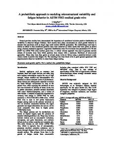
5.3 Simulation Results We have developed a simulation and animation package using Matlab/Simulink. Fig. 6 shows a snap shot of the animation as the rover moves over uneven terrain. It embodies the kinematics and rover-terrain interaction model, and displays time-varying rover quantities such as position, orientation, and joint angles. It also allows zooming and alternative perspective views, e.g. top, down and side. The terrain shown in Fig. 7, consists of a bump which is wavy (sinusoidal) on the left side and smooth on the right side under the rover. The rover moves on a straight path with a constant speed of 1 cm/s. The traces of the front wheels are shown in Fig. 7. The rover reference point is at the origin (X= Y=0) at time t = 0. Fig. 8 shows the rover body roll Φ x and pitch Φ y as the results of combined motion of six wheels. When the rover reference point moves about 9.1 cm, the front wheels hit the bump at X= 50 cm (Fig. 9), the rover pitch changes from zero to a positive value and then oscillates due to the wavy terrain profile. The rover pitch is initially positive until the rover reaches the top of the bump. The rover roll oscillates due to different terrain profile under the right and left wheels.
Fig. 9 shows the rover joint angles including the rocker angle ρ , and left and right bogie angles β1 and β 2 . The rocker and left bogie angles, ρ and β1 , oscillate as the left wheels traverse the wavy bump. There are both amplitude and phase differences between ρ and β1 , with the rocker having a lower amplitude than the left bogie due to the fact that the bogie is shorter in length than the rocker (See Fig. 5). The right bogie experiences transitions between the time when the middle and back wheels hit the bump, and again when these two wheels leave the bump. Note that the right bogie does not oscillate since the terrain is smooth on the right side. .The terrain shown in Fig. 7, consists of a bump which is wavy (sinusoidal) on the left side and smooth on the right side under the rover. The rover moves on a straight path with a constant speed of 1 cm/s. The traces of the front wheels are shown in Fig. 7. The rover reference point is at the origin (X= Y=0) at time t = 0. Fig. 8 shows the rover body roll Φ x and pitch Φ y as the results of combined motion of six wheels. When the rover reference point moves about 9.1 cm, the front wheels hit the bump at X= 50 cm (Fig. 9), the rover pitch changes from zero to a positive value and then oscillates due to the wavy terrain profile. The rover pitch is initially positive until the rover reaches the top of the bump. The rover roll oscillates due to different terrain profile under the right and left wheels. Fig. 9 shows the rover joint angles including the rocker angle ρ , and left and right bogie angles β1 and β 2 . The rocker and left bogie angles, ρ and β1 , oscillate as the left wheels traverse the wavy bump. There are both amplitude and phase differences between ρ and β1 , with the rocker having a lower amplitude than the left bogie due to the fact that the bogie is shorter in length than the rocker (See Fig. 5). The right bogie experiences transitions between the time when the middle and back wheels hit the bump, and again when these two wheels leave the bump. Note that the right bogie does not oscillate since the terrain is smooth on the right side.
2023
IEEE Int. Conf. on Systems, Man and Cybernetics, 2005.
Rocker and Bogie Joints 20 rocker left bogie right bogie
15 100
10 joint an gle (de gs)
z (cm)
80 60 40 20
5 0 -5
-10
0 50
-15
400 0
300 200
-20 0
100 -50
y (cm)
0
50
100
x (cm)
Fig. 7 Traces of front wheels over unsymmetrical wavy bump
150
200 t (secs)
250
300
350
400
Fig. 9 Rocker and bogie joint angles for straight path.
Rover Pitch and Roll
References
15 pitch roll
10
a ttitu d e (d e g s)
5
0
-5
-10
-15
-20 0
50
100
150
200 250 t (secs)
300
350
400
Fig. 8 Rover roll and pitch for straight path
6. Conclusions A methodology is presented for developing kinematic models of articulated rovers. The kinematic model allows full 6-DOF motion and is applicable to any high mobility wheeled rover traversing uneven terrain. Three types of kinematics are identified in the paper including navigation, slip, and actuation. In particular, slip kinematics can be used to detect various wheels slips to reduce undesirable motions. Actuation kinematics makes it possible to determine individual wheel speed and steering commands to achieve coordinated motion, which is important for rough terrain traversals. The kinematics modeling and analysis has been applied to a prototype Mars rover, and the simulations show consistent and expected results. Finally, there are several limitations of the proposed kinematics models and analyses that we are currently investigating. These include dealing with multiple and discontinuous wheel-terrain contact points, deformable terrain (e.g. sand). Nevertheless, the proposed models and analyses should provide useful tools for studying behaviors of articulated rovers under a variety of situations and terrain topologies. They can also be used at the design stage to investigate the rover performance under different kinematics arrangements and parameters.
[1] S. Hayati, R. Volpe, P. Backes, J. Balaram, R. Welsh, et al “The Rocky 7 Rover: A Mars Sciencecraft Prototype”, Proc. IEEE Int. Conf. Robotics and Automation, pp. 24582464, Albuquerque, N.M. 1997. [2]http://robotics.jpl.nasa.gov/tasks/scirover/homepage.html . [3] Ch. DeBolt, Ch. O’Donnell, S. Freed, and T. Nguyen, “The bugs ‘basic uxo gathering system’ project for uxo clearance and mine countermeasures,” Proc. IEEE Int. Conf. Robotics and Automation, pp. 329-334, Albuquerque, N.M., 1997. [4] Joint Robotic Program, UGV Master Plan, Department ofDefense,www.jointrobotics.com/activities_new/masterpl an.shtml, 2002. [5] P.F. Muir and C.P. Neumann, “Kinematic modeling of wheeled mobile robots,” J. Robotic Systems, vol. 4, no. 2, pp. 282-340, 1987. [6] K. Iagnemma and S. Dubowski, “Vehicle-ground contact angle estimation with application to mobile robot traction,” Proc. 7th Int. Conf. on Advances on Robot Kinematics, Ark ’00, pp. 137-146, 2000. [7] J. Balaram, “Kinematic observers for articulated rovers,”, Proc. IEEE Int. Conference on Robotics and Automation, pp. 2597-2604, San Francisco, CA, 2000. [8] M. Tarokh, G. McDermott, S. Hayati, and J. Hung, “Kinematic modeling of a high mobility Mars rover,” Proc. IEEE Int. Conf. Robotics and Automation, pp. 992-998, Detroit, MI, 1999. [9] P. S. Schenker, et al “Reconfigurable robots for all terrain exploration,” Proc. SPIE Vol. 4196, Sensor Fusion and Decentralized Control in Robotic Systems III, 15 pp., Boston, MA, Nov. 2000. [10] R. Volpe, "Navigation Results from Desert Field Tests of the Rocky 7 Mars Rover Prototype" International Journal of Robotics Research, Special Issue on Field and Service Robots, 18(7), July 1999. [11] J. J. Craig, Introduction to Robotics, 2nd Ed, Adelson-Wesley Publishing, 1989. [12] M. Tarokh and G. MacDermott, “Kinematics modeling and analyses of articulated rovers,” wwwrohan.sdsu.edu/~tarokh/lab/paper, 2004.
2024