(for re-localization), station descriptions for dock- ing and load ... This hierarchy authorizes a \light" cooperation, when possible, and .... Ethernet - TCP/IP. Central.
Preprints of the Fourth International Symposium on Experimental Robotics, ISER'95 Stanford, California, June 30{July 2, 1995
A General framework for multi-robot cooperation and its implementation on a set of three Hilare robots R. Alami, L. Aguilar, H. Bullata, S. Fleury, M. Herrb, F. Ingrand, M. Khatib, F. Robert LAAS / CNRS 7, Avenue du Colonel Roche 31077 Toulouse - France
1. Introduction
robot demonstration involving three Hilare robots.
We present an implemented system which allows to run a eet of autonomous mobile robots in a route network or an in-door environment with a very limited centralized activity. The robots are endowed with all the necessary ingredients for planning and executing navigation missions expressed at a very high level as well as for multi-robot cooperation. The system is based on a generic paradigm called Plan-Merging Paradigm, where robots incrementally merge their plans into a set of already coordinated plans. This is done through exchange of information, between robots, about their current state and their future plans. The robot architecture is derived from the generic architecture developed at LAAS. The software tools we use allow us to run the robot software under VxWorks on real robots (from the Hilare family) as well as on Unix workstation emulating the behavior of the robot. A test and evaluation environment has been developed which includes a 3D graphic system to display the complete eet of robots (dozen or even more) evolving in their environment (usually a route network connecting docking/un-docking areas). This testbed provides mechanisms such that each robot is fully functional and can be ran on independent Unix workstation. The same 3D graphic system can also be used as a server which draws periodically the positions of the real robots in the model as well the result of the various actions they perfrom (landmark-based localization, obstacle modelling, pick-up and put-down actions ). Numerous tests on various environments have been performed. Two examples will be presented in the following: (1) a simulation based example which runs ten robots in an in-door environment, and (2) a real
2. A �eet of Autonomous Mobile Robots The problem consists in devising a system which allows to run a large eet of autonomous mobile robots in a route network (resp. in-doors) composed of lanes (corridors), crossings and open areas (rooms). Typical applications of this problem are load transshipment as dealt with in the MARTHA project1 which requires the development of a large eet of autonomous mobile robots for the transportation of containers in harbors, airports and railway station environments. The Plan-Merging Paradigm we propose is well suited to such applications as it allows to deal with a great number of robots, locally dealing with con icts while maintaining a global coherence of the system. Indeed, it limits the role of the central system to the assignment of tasks and routes to the robots (without specifying any trajectory or any synchronization between robots) taking only into account global tra�c constraints.
2.1. Mission speci�cation
The system is composed of a Central Station and a set of autonomous mobile robots. As mentioned above, the environment is a route network composed of entities like lanes, crossings and open areas. Basically, the robots navigate through an oriented graph of cells. Lanes and crossings are composed of a set of connected cells, while areas consist of only one cell. Thus, the environment model, which is provided to each robot, mainly contains topological and geometric
:::
1 MARTHA: European ESPRIT Project No 6668. \Multiple Autonomous Robots for Transport and Handling Applications"
1
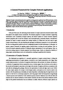
Figure 1. An environment model with 10 simulated robots the environment as well as the availability of such or such robot. However, it does not further specify the sequence of robots going through a crossing (this decision is left to the robot locally concerned), nor does it require the robot to remain on the speci ed lanes (in case it needs to move away from an unexpected obstacle).
information: A network describing the connections of areas and crossings by oriented lanes. This is the only information used by the Central Station to elaborate routes for robots. A lower level topological description (cell level). The graph of cells is oriented, in order to provide a nominal (but not exclusive) direction for lanes and crossings use. However, cells adjacency is also provided in order to allow robots to use complementary spatial resources when necessary. A geometrical description of cells (polygonal regions). Additional information concerning landmarks (for re-localization), station descriptions for docking and load handling actions.
2.2. A Plan-Merging Protocol for Multi-Robot Navigation The cooperation scheme we use is based on a general paradigm, called Plan-Merging Paradigm �2], where robots incrementally merge their plans into a set of already coordinated plans. This is done through exchange of information about their current state and their future actions. For the case of a number of mobile robots in a route network environment, we have devised a speci c PlanMerging Protocol based on spatial resource allocation (see �3]). It is an instance of the general protocol described in �2], but in this context, Plan-Merging Operation (PMO) is done for a limited list of required resources (a set of cells which will be traversed during the plan to merge). Due to place limitations, we will not describe in more detail this protocol. A full
Figure 1 illustrates a typical environment model and its associated cell topology. In the developed system, the central station is in charge of producing the high level plans. The plans produced takes into account the topological model of 2
description may be found in �2]. One of the most interesting attributes of this protocol is that it allows several PMOs to be performed simultaneously if they involve disjunctive resource sets. This is particularly useful when there are several local con icts at the same time. Plan-Merging for cell occupation In most situations, robot navigation and the associated Planmerging procedure are performed by trying to maintain each cell of the environment occupied by at most one robot. This allows the robots to plan their trajectories independently, to compute the set of cells they will cross and to perform Plan-Merging at cell allocation level. We have chosen an allocation strategy which makes the robots allocate one cell ahead when they move along lanes, while for crossing, they must allocate all the cells necessary to traverse and leave it. This is done in order not to constrain unnecessarily the other robots.
The Decisional Level which includes the re nement of the tasks and a coherent control of the actions, calls for centralized knowledges and decisions, whereas the Functional Level, the reactive part of the architecture, calls for a distribution of the low level functions (e.g. the sensor/actuator control loops).
3.1. The Decisional Level
From an architecture point of view, the decisional level is organized into three independent layers running in parallel: a mission layer, a coordination layer and a execution layer (Figure 2) . At each layer planning aspects and supervision or control aspects are independent and run separately to satisfy di�erent response time constraints �1]. Decisional level or Robot Supervisor
Planner
When reasoning about cells is not su�cient While, most of the time, the robots may restrict their cooperation to cells allocation, there are situations where this is not enough. This happens when they have to cross non-structured areas (rooms) or when an unexpected obstacle, encountered in a lane or in a crossing, forces a set of robots to maneuver simultaneously in a set of cells. In such situations, a more detailed cooperation (using the same protocol but a di�erent planner: the motion planner) takes place allowing robots to coordinate their actions at trajectory level. Thus, we have a hierarchy of PMOs 1. rst, at the cell level, based on resource (cells) allocation 2. then, depending on the context, at trajectory level: motion planning in a set of common cells determined by the rst level This hierarchy authorizes a \light" cooperation, when possible, and a more detailed one, when necessary.
Planner
Functional level
Figure 2. The robot supervisor architecture The mission layer deals with the mission re nement, the mission control and Central System interactions. The mission (see a typical mission in Figure 3) are rst re ned as if the robot was alone. Re nement consists in planning all trajectories2 according to the speci ed actions (dock, un-dock, load or un-load). The plan is annotated with cell entry and exit monitoring operations which will be used to maintain the execution state of the robot and to synchronize its action with other robots. Figure 4 shows a re ned plan corresponding to the re nement of the rst action of the mission in Figure 3 (the robot being at the end of the lane 0).
3. The Robot Control System
The Robot Control System (RCS) architecture is derived from the generic control architecture for autonomous mobile robots developed at LAAS �4, 1, 6]. The control architecture of an autonomous robot must include both some decision-making processes, embedded in the Decisional Level, and real-time execution processes which are gathered in the Functional Level.
2 Currently the route, is given by the Central Station, however we plan to add some route planning capabilities in a near future.
3
(mission (. (action 1 (goto (station 1)) (using (lane 10))) (action 2 (dock)) (action 3 (putdown)) (action 4 (undock)) (action 5 (goto (station 3)) (using (lane 12) (lane 8))) (action 6 (dock)) (action 7 (pick-up (container 5))) (action 8 (undock)) (action 5 (goto (end-lane 0)) (using (lane 9) (lane 0))) .))
(coordination-plan (.(exec-plan 1 (report (begin-action 1))) (exec-plan 2 (wait-exec-event robot-3 9)) (exec-plan 3 (wait-exec-event robot-7 48)) (exec-plan 4 (monitor (entry (cell 4)))) (exec-plan 5 (monitor (entry (cell 5)))) (exec-plan 6 (monitor (exit (cell 14)))) (exec-plan 7 (monitor (exit (cell 4)))) (exec-plan 8 (exec-traj 0)) (exec-plan 9 (exec-traj 1)) (exec-plan 10 (exec-traj 2)) .))
Figure 3. Example of mission sent by the Central Station
Figure 5. Example of coordination plan tored in order to produce exchanged execution events. If \trajectory level" plan merging has been necessary, then concerted curvilinear abscissa are monitored.
(plan (. (plan-step 1 (report (begin-action 1))) (plan-step 2 (monitor (entry (cell 4)))) (plan-step 3 (monitor (entry (cell 5)))) (plan-step 4 (monitor (exit (cell 14)))) (plan-step 5 (monitor (exit (cell 4)))) (plan-step 6 (exec-traj 0)) (plan-step 7 (exec-traj 1)) (plan-step 8 (exec-traj 2)) (plan-step 9 (monitor (entry (cell 0)))) (plan-step 10 (monitor (exit (cell 5)))) (plan-step 11 (monitor (entry (station 1)))) (plan-step 12 (exec-traj 3)) (plan-step 13 (exec-traj 4)) (plan-step 14 (exec-traj 5)) (plan-step 15 (report (end-action 1))) .))
3.2. The Functional Level
The functional level implements all the basic capabilities of the robot in sensing, acting and computing. These functionalities are grouped according to data or resource sharing, and integrated into modules. Beside real time capabilities to insure closed-loop control and reactivity, this level ful ll several conditions towards the others layers: bounded response time to request, observability and programmability. To make easier the integration of a module in the system, a standardization of the module behavior has been speci ed (see �6]) and used. Roughly, the structure of a module is composed of a control level and an execution level. The control capacities are related to the handling of requests and replies and the control of the functions of the execution level. At the execution level, the implemented functions (i.e. embedded algorithms) are classi ed in four categories according to their execution modalities (i.e. starting and ending conditions, periodicity, ...), and consequently the way to control them : servers, �lters, servo-processes, monitors. All these functions are interruptible by the module controller. They can also abort by themselves if the execution cannot be achieved (internal fail, fail of a server at a lower level...). Figure 6 shows the functional level, for the presented application, including 7 modules, their client/server relations and 3 exported data (posters). The Robot Supervisor is a client of all the modules of the functional level. It manages itself the poster named ENVIRONMENT which exports the topological and geometrical model of the environment (cf x2.1).
Figure 4. Example of re ned mission
The coordination layer is involved in plan merg-
ing operations, interactions with others robots (plans or events exchange), the control of the plan and the production of the coordination plan. Actually before executing its plan, the robot must validate it in the multi-robot context. This is done through incremental plan merging. The plan merging protocol allows the coordination supervisor to incrementally build a new plan called the coordination plan. This plan speci es all trajectories and actions to be executed, but also all events to be monitored and sent to another or awaited from another robot. Note that this plan is also the one exchanged between robots during plan merging operations. Figure 5 presents a coordination plan example corresponding to the 8 rst plan steps of the re ned mission geiven above. The execution layer is in charge of the interpretation and the execution of the coordination plan. As a result, it is responsible of most interactions with the functional level. The coordination plan is executed while taking into account synchronization between robots. When plan merging is done only at the \cell allocation level" entry or exit of cells are moni4
detecting the entry of exit of regions for synchronization purposes, as established after a Planmerging operation. The External Communication Modules: two independent systems which handle the communication with the Central Station and the direct communication between robots. This last one allows also to broadcast messages to all robots.
Figure 6. Architecture and interactions of the functional level The Modules currently implemented are: The Motion Planner Module: it is composed of a Topological Planner, a Geometrical Planner and Multi-robot Scheduler. It is used in order to compute not only feasible trajectories but also synchronization events between di�erent robot trajectories.
Figure 7. An example of an obstacle avoidance
4. Implementation of a Realistic Testbed
We have developed a complete robot control system which includes all the features described above. The robot supervisor is coded using a procedural reasoning system: C-PRS �8, 7]. The target implementation runs on-board a multi-processor VME rack, under the VxWorks real-time system. Simulated environments: For testing and demonstration purposes we have built an emulation of the communication and multi-tasking primitives of the real-time system, that allows us to run all elements of a robot (the supervisor and all functional modules) on a Unix workstation as a set of Unix processes. The motion execution is simulated at the lowest level by sending the elementary motion controls into the perception sub-system. Radio communications between robots and with the central station are simulated on the Ethernet network. Moreover, for the purpose of simulation, virtual obstacles can be given to the external perception module.
The Motion Execution Module �10]: this modules embeds all robot motion primitives. The Local Obstacle Avoidance Module �9]: this module allows to execute (non-holonomous) trajectories while avoiding (when possible) unknown obstacles. Figure 7 illustrates an example of its capabilities. The External Perception Module �5]: which allows to perform landmark-based (wall and xed furniture) localisation (see Figure 8) and to build, when necessary, a model of the local obstacles. This feature is used to update the world model after the detection of a situation which requires a drastic change of a planned trajectory. The Position Monitoring Module: this modules provides a variety of position based monitors for 5
CCS
Robot Control Systems
Ethernet - TCP/IP
Unix 3D graphic server
Unix
rs-232 + modem
rs-232 + modem
rs-232 + modem
hilare 2 b
hilare 2
Central Control Station
Unix
hilare 1.5
Hilare 1.5
RCS-3
Hilare 2 b’
RCS-2
Hilare 2
RCS-1
Figure 9. The experimental testbed
Figure 8. An example of re-localisation based on walls and furniture Their presence near the robot will be detected and signaled to the supervisor. A 3-D graphic server has been built in order to visualize the motions and the load operations performed by all the robots in their environment (Figures 1,10-12). It receive position updates from the motion execution modules of all the robots, each running on its own workstation. Experiments have been run successfully on a dozen of workstations (each workstation running a complete robot simulator). Figure 1 is a snapshot of a typical run: 10 robots in an in-door environment. An experiment using three real robots We have also tested the implementation an run several demonstrations on three real mobile robots. Figure 9 illustrates the hardware used in the experimental testbed. The 3D graphic system can also be used as a server which draws periodically the positions of the real robots in the model as well the result of the various actions they perfrom (landmark-based localization, obstacle modelling, pick-up and put-down actions ). An example of such use is represented in Figure 13.
Figure 10. Crossing (Step 1) Crossing, Step 1 (Figure 10): This snapshot has been modi ed to present the routes the robot must follow.
We shall now illustrate the plan-merging paradigm and its capabilities with some sequences from our experimentation with simulated and real robots in an
Robot r3, coming from position A, and r0 have disjunctive list of resources. Therefore, they can perform PMOs in parallel and traverse the crossing without any synchronization.
indoor environment. The rst example presents a PMO at a crossing with simulated robots, the second, a PMO in an open area with real robots.
An example of PMOs at a crossing (simulation)
:::
5. Results
6
exit its current cell) and its PMO succeed, but it must synchronize with r2 and r3 .
Crossing, Step 3 (Figure 12): Robot r2 frees the crossings cells and sends the corresponding execution event to r9. Robot r9 can now traverse the crossing.
An example of PMOs in an Open Area: 3 real robots in the LAAS robotics room As mentioned earlier, open areas are not exclusive resources. In our example (see the gure 14 and 13 which represent the same situation in 3D and 2D), r11 (Hilare 2) goes from station S5 to Lane 0, r12 (Hilare 2b) moves backward from station S3 to station S5, and r13 (Hilare 1.5) from station S4 to station S3. After synchronizing at the PMO level, the three robots eventually performed theirs PMOs, at the \trajectory level", in the following order: r11, r12 and r13. In short, r13 waits for r12 to move away, and r12 waits until r11 clears its path. If we analyze the situation more carefully, one can see that r12 will move until position Wait11, at which point, it will wait until r11 reaches the point Notify12 and then noti es r12 of this event. As a consequence, r12 will proceed to station S5 and will notify R13 (upon reaching point Notify13), which is waiting at point Wait12, that it can now proceed to station S3. To conclude on these two examples presented above, one can note the following interesting properties of the PMO:
Figure 11. Crossing (Step 2)
Figure 12. Crossing (Step 3) Robot r9 follows r3, but its PMO fails (because r3 has not yet planned an action to free the cell r9 must allocate to exit the crossing). As a result r9 must wait a planning events from r3 (i.e. a new PMO). Robot r2, which wants to go in position B, can merge its plan into the incrementally build local plan.
Planning and execution is done in parallel. Several robots may use the crossing simultaneously (r0 and r3). The example exhibits the two types of synchronization: synchronization based on execution events (r11, r12 and r13 in the area example) and synchronization based on planning events (r9 and r3 in the crossing example). Each robot produces and merges its plans iteratively, and the global plan for the use of the crossing is incrementally built through several PMOs performed by various robots. It is not a rst arrived rst served execution. In the crossing example r9 arrived second, was blocked by r3, but did not block the crossing and let r2 enter the crossing before.
Crossing, Step 2 (Figure 11): Robot r2 traverses the crossing, after an execution synchronization with r0 (it must wait until r0 leaves the lower left cell of the crossing before entering it). Robot r9 has received the awaited \planning event" from r3 (which as now planned action to 7
Figure 13. The three Hilare in the robotics room (1)
6. Conclusion
Figure 14. The three Hilare in the robotics room(2)
The system described in this paper paper presents many original contributions to the eld of research on 8
autonomous mobile robot. To our knowledge, it is is
the rst time such a large eet of autonomous robot is put together to execute high level missions given by a central station. Our experimentation using large number of emulated robots has shown the feasibility and the embarkability of our solution. The Plan-Merging Paradigm we propose has the following properties�
4] R. Chatila, R. Alami, B. Degallaix, and H. Laruelle. Integrated planning and execution control of autonomous robot actions. In IEEE International Conference on Robotics and Automation, Nice, (France), 1992. 5] M. Devy and H. Bulata. Landmark-based vs Featurebased Localization of a Mobile Robot in a Structured Environment. In International Conference on Advanced Robotics (ICAR), Barcelone (Spain), 1995. 6] S. Fleury, M. Herrb, and R. Chatila. Design of a modular architecture for autonomous robot. In IEEE International Conference on Robotics and Automation, San Diego California, (USA), 1994. 7] F. F. Ingrand, R. Chatila, R. Alami, and F. Robert. Embedded control of autonomous robots using procedural reasoning. In International Conference on Advanced Robotics (ICAR), Barcelone (Spain), 1995. 8] F. F. Ingrand, M. P. George�, and A. S. Rao. An Architecture for Real-Time Reasoning and System Control. IEEE Expert, Knowledge-Based Diagnosis in Process Engineering, 7(6):34{44, December 1992. 9] M. Khatib and R. Chatila. An extended potentiel �eld approach for mobile robot sensor-based motions. Intelligent Autonomous Systems (IAS'4), Karlsruhe (Germany), Eds E. rembold, R. Dillmann, L.O. Hertzberger, T. Kanade, IOS Press, pages 490{496, 1995. 10] S.Fleury, P.Soueres, J.P.Laumond, and R.Chatila. Primitives for smoothing mobile robot trajectories. IEEE International Conference on Robotics and Automation, Atlanta (USA), 2-6 Mai 1993, pp.832-839, 1993.
1. It \ lls the gap" between centralized, very high level planning and distributed execution by a set of autonomous robots in a dynamic environment. 2. It makes possible for each robot to produce a coordination plan which is compatible with all plans executed by other robots. 3. No system is required to maintain the global state and the global plan permanently. Instead, each robot updates it from time to time by executing a PMO. 4. The PMO is safe, because it is robust to plan execution failures and allows to detect deadlocks. The current implementation have shown that the protocol works and allows for far more than ten robots to cooperate. In fact, considering the locality of the con ict resolution, i.e. the ability of robots in a group to coordinate their plans and actions without disturbing the rest of the eet, one can easily see that this protocol can scale to a much larger number of robots (hundreds). This protocol allowed us to make a large number of autonomous robots behave coherently and e�ciently without creating a burden on the central system activity. The nal version of the paper will report in more details on the experiments performed using three Hilare robots. It will also give a brief review of the literature.
Acknowledgments: This work was partially sup-
ported by the MARTHA (ESPRIT III) Project, the CNRS, the R�egion Midi-Pyr�en�ees and the ECLA ROCOMI Project. This project is the fruit of a very intensive collaboration between numerous researchers. We would like to acknowledge the help and the e�ective involvement of S. Suzuki, J. Perret, T. Sim�eon, M. Devy, G. Bauzil, C. Lemaire, B. Dacre-Wright, C. Dousson, P. Gaborit.
References
1] R. Alami, R. Chatila, and B. Espiau. Designing an intellingent control architecture for autonomous robots. In International Conference on Advance Robotics. ICAR'93, Tokyo (Japon), November 1993. 2] R. Alami, F. Robert, F. F. Ingrand, and S. Suzuki. A paradigm for plan-merging and its use for multi-robot cooperation. In IEEE International Conference on Systems, Man, and Cybernetics, San Antonio, Texas (USA), 1994. 3] R. Alami, F. Robert, F. F. Ingrand, and S. Suzuki. Multi-robot cooperation through incremental planmerging. IEEE ICRA'95, Nagoya, Japan, 1995.
9