A general map matching algorithm for transport telematics applications
Mohammed A. Quddus Washington Y. Ochieng Lin Zhao Robert B. Noland Centre for Transport Studies Dept. of Civil and Environmental Engineering Imperial College London London SW7 2BU Ph: 020 7594 6100 Email:
[email protected]
Abstract This paper describes the features of a map-matching algorithm designed to support the navigational function of a realtime vehicle performance and emissions monitoring system currently under development, and other transport telematics applications. The algorithm is used together with the outputs of an extended Kalman filter formulation for the integration of GPS and dead reckoning data, and a spatial digital database of the road network, to provide continuous, accurate and reliable vehicle location on a given road segment. This is irrespective of the constraints imposed by the operational environment, thus alleviating outage and accuracy problems associated with the use of stand-alone location sensors. The map-matching algorithm has been tested using real field data and has been found to be superior to existing algorithms, particularly in how it performs at road intersections.
Key words: Transport telematics, GPS, map-matching, land vehicle navigation and optimal estimation.
1
INTRODUCTION
Systems for monitoring and tracking vehicle movement offer many opportunities for the management of transport systems. The data collected from such systems also has the potential to provide a fuller understanding of the behavior of travelers and the consequences of that behavior both on the transport system and external effects, such as emissions of pollutants. This paper reports on a research and development project to create and demonstrate the capabilities of an accurate, reliable and cost effective real time data collection device, the vehicle performance and emissions monitoring system (VPEMS). The VPEMS will be fitted on vehicles to monitor vehicle and driver performance and, the level of emissions and concentrations.
The navigation function of the VPEMS is responsible for the derivation of all spatial, temporal and spatio-temporal data of the vehicle including location in 3-dimensional space, time, slope, speed and acceleration. Because of the required navigation performance (RNP) to be achieved in built-up areas where the impact of pollution from traffic is most serious, the navigation function cannot be supported by the global positioning system (GPS) alone. One possible solution is the integrated use of data from GPS with dead reckoning (DR) and map matching (MM). An extended Kalman filter (EKF) has been developed for the integration of GPS and low-cost dead reckoning sensor data (Zhao et al., 2002). This paper reports on the linking of the EKF is with a new map matching algorithm to accurately locate a vehicle on a given road segment.
Positioning sensors such as GPS or even the integrated GPS/DR system employing EKF algorithms fail to provide the actual location of a vehicle on a given road segment. This is due to the various errors sources that affect such systems. The availability of higher accuracy digital spatial road network data should make it possible to account for these errors and enable the actual vehicle position on a given road to be determined. This technique is often called map matching (MM). A formal definition of MM can be found in Bernstein and Kornhauser (1996), White et al. (2000) and Greenfeld (2002). The most complex algorithm is the general MM algorithm that does not assume any knowledge or any other information regarding the expected location of the vehicle.
2
The objective of this paper is to describe the limitations of existing MM algorithms and describe a general algorithm, which is essential for the VPEMS project and other telematics applications. The proposed MM algorithm uses the output of the GPS/DR EKF algorithm. Its performance has been validated using data from a representative built-up environment (the Greater London area).
2
EXISTING LITERATURE ON MAP MATCHING
Map matching procedures vary from those using simple search techniques (Kim et al., 1996), to those using more complex mathematical techniques such as Kalman Filters (Tanaka et al., 1990). A number of different algorithms have been proposed for MM for different applications, each of which has advantages and disadvantages (Table 1). Some of these are reviewed below.
Bernstein and Kornhauser (1996) describe several algorithms (or parts of algorithms) for matching an estimated position to a network representation of the street system. Two things are apparent from this study. Firstly, it is clear that this is a complex and fairly difficult task. Point-to-point and curve-to-point matching are unlikely to work very well, especially when there are errors in the position and/or errors in the network representation. Hence, other, more complicated algorithms must often be used. Secondly, though a number of different algorithms can be used, it seems clear that it is both important to perform some kind of curve-to-curve matching and to incorporate topological information in the algorithm. Bernstein and Kornhauser conclude that the more attention is given to the topological information, the better the algorithm should perform.
White et al. (2000) describe several algorithms (or parts of algorithms) for matching an estimated position to a network representation of the street system and attempt to evaluate four of them. Since most route changes occur at intersections, their study suggests that particular attention needs to be paid to the problems that arise at intersections. The discussion focuses on urban routes since most algorithms appear to work well on highways. However, they recommend that the algorithms need to be evaluated on a wider array of routes especially in urban areas. The limited number and variety of routes considered in their study preclude general conclusions from being made.
3
Taylor et al. (2001) propose a novel method of map matching using differential GPS and height aiding, referred to as the road reduction filter (RRF) algorithm. The general approach used is to improve the accuracy of the computed position of a vehicle via differential corrections and height aiding. The simple procedure used allows identification of all possible candidates for the correct road while systematically removing the wrong ones. The RRF algorithm is improved using road centre-line network connectivity. The method was developed to cater for errors introduced by GPS selective availability (S/A) which was subsequently turned off in May 2000 (Ochieng and Sauer, 2001). Its benefits are still to be assessed in the S/A free environment.
Greenfeld (2002) reviews several approaches for solving the map matching problem and proposes a weighted topological algorithm. The algorithm is based on assessing the similarity between the characteristics of the street network and the positioning pattern of the user. The algorithm seems to work well even with relatively inferior or bouncy GPS data. Tests show that the procedure computes correct matches virtually everywhere. However, their study suggests that additional research is required to verify the accurate performance of the algorithm and to make an accurate position determination on a given road segment.
Table 1: Summary of literature Procedures
Author (s), year
Algorithm
Comments/Disadvantages
Bernstein and Kornhauser (1996) Kim et al (1996) White et al (2000)
Map matching as a Map the GPS tick to the search problem. ‘closest’ node or shape Or point in the network Point-to-Point matching
a) only geometric information b) never makes use of ‘Historical’ information c) very sensitive to the way in which the network was digitized. That is, other things being equal, arcs with more shape points are more likely to be matched to
Bernstein and Kornhauser (1996) White et al. (2000) Taylor et al. (2001)
Point-to-Curve matching Map the GPS tick to the ‘closest’ arc in the network (minimum distance from the point to the curve)
a) only geometric information b) lack of the use of historical information and hence sometimes assign incorrect link c) quite unstable
4
White et al. (2000)
Point-to-Curve matching Same as Point-to-Curve with heading matching algorithm except that it makes use of the heading information. If heading of the current GPS trick is not comparable to the heading of the arc, then the arc is discarded.
a) better algorithm than point-tocurve matching b) GPS heading is sometimes very inaccurate especially when the vehicle speed is zero or very low. Therefore, incorrect matching is unavoidable.
Bernstein and Kornhauser (1996) White et al. (2000) Taylor et al. (2001)
Curve-to-Curve matching
Match arcs defined by a series of GPS point positions with arc defined by a set of points that define partial road centreline. One method used for matching two curves (arcs) is to use the distance between them.
a) geometric information. b) quite sensitive to outliers. c) sometimes yield unexpected and undesirable results
Bernstein and Kornhauser (1996) White et al. (2000)
Improving Point-toCurve matching
Given a known initial point, the topology of the network makes it possible to reduce the set of likely arcs dramatically
Both geometric and topological information are used. But quite sensitive to the threshold that is used. One bad match can lead to a sequence of bad matches.
Bernstein and Kornhauser (1996) White et al. (2000)
Improving Curve-toCurve matching
Topological information of the network is used with curve-to-curve matching
very complex to implement and a real world experiment does not consistently out perform other algorithms.
Krakiwsky et al. (1988) Scott and Drane (1994) Jo et al. (1996)
Map matching as a statistical estimation
In this approach, one considers a sequence of points and attempts to fit a curve to them. This curve is constrained to lie on the network
It is particularly elegant when the model describing the ‘physics of motion’ is simple e.g., movement is only possible along a straight line. Unfortunately, in most practical applications, the physics of motion is dedicated by the network. This makes it quite difficult to model
Greenfeld, J.S. (2002)
Similarity criteria by weighting system
Topological analysis of road network
a) much more likely to be simple and correct b) but sometimes assigns incorrect links especially at intersections c) determination of vehicle position is not robust
It is clear from existing literature that a key component of any MM algorithm is to identify the correct link among the candidate links since one bad match can lead to a sequence of bad matches. The literature review has also revealed that particular attention has to be paid to topological aspects of the road network, matching processes at intersections and algorithm validation in complex route structure environments such as in built-up urban areas.
5
3
SOME LIMITATIONS OF EXISTING MAP MATCHING ALGORITHMS
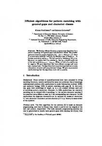
Most of the limitations of the existing algorithms have been explained in White et al (2000) and Greenfeld (2002). However, other additional limitations that should be addressed can be easily identified. Examples of these are illustrated in Figures 1 and 2. P20
I
J
4 C
5
F P10
P11 3
2
B
G P16
H
D 1 P1
E
A
Figure 1: Incorrect match without the vehicle heading information at junction
In Figure 1, the points P1 to P20 represent the GPS/DR positions of a vehicle traveling on a sample network. It is relatively easy in this case to determine that vehicle path is represented by 1-2-3-4. Applying the Greenfeld (2002) algorithm or any other algorithm explained in the above section, it is found that these points correctly match on the link until P10. However, at point P11, it selects link-5 as a correct link since the orientation of the GPS line between P11 and P12 is similar to link-5. The reason why the algorithm assigns an incorrect link is that it has not taken into account any heading information of the vehicle at P11. There are many cases similar to this example. GPS/DR headings are fairly accurate and could be used to provide additional information in facilitating a correct identification of the link.
It is also possible to obtain GPS/DR positions as shown in Figure 2. Between points P9 and P27 the vehicle is stationary for about 18 seconds.
The various points in between P9 and P27 reflect the error in GPS position determination. It is
obvious that it would not be possible to identify the correct link either using the algorithm proposed by Greenfeld (2002) or any of the other map matching procedures described in the literature review section. One way to overcome this problem is to consider speed information from GPS/DR and assume a single position fix when the vehicle is stationary (i.e. zero speed).
6
D 2 P9 P1
P27
C
3
B
1
A
4
E
Figure 2: Random GPS/DR points when the vehicle is stationary
Another limitation of existing MM algorithms is associated with the determination of the actual vehicle position on the selected link. Most algorithms adopt a simple perpendicular projection of the positioning sensor derived position onto the selected link and ignore the numerous errors associated with the positioning sensors and the spatial road network mapping data.
To overcome all stated limitations, a general MM algorithm is proposed in this paper which is described in the next section.
4
DESCRIPTION OF THE MAP MATCHING ALGORITHM
The MM algorithm analyzed in this paper seeks to correct for some of the deficiencies of other methods as previously described. The basic characteristics of the algorithm include the use of output from the GPS/DR EKF algorithm developed by Zhao et al. (2002), including position, velocity, and time. Information on the vehicle trajectory is used to avoid sudden switching of mapped locations between unconnected road links. The topological aspects of the road network and GPS/DR heading and speed information allow improvements in performance of the algorithm, especially at intersections. In addition the physical location of the vehicle on the selected link is determined from the weighted averages of the two state determinations. The weighting factors are determined empirically, as described further below. Finally, the errors associated with the bearing of the link (due to the map resolution and curvature of the
7
link) and positioning sensors are considered to determine the physical location of the vehicle on the link. The details of the algorithm are described below by first describing and defining the data inputs, .followed by a description of the map matching process, and a procedure for identifying data outliers.
4.1
Definition of Data Inputs
There are a several ways to represent digital spatial road network data. The planar model is currently one of the most commonly accepted models because of its high efficiency and low complexity. In the planar model, which is used in this study, network representation (N) of a street system ( N ) consists of a set of curves in R2, each of which is called an arc. Each arc is assumed to be piece-wise linear. Therefore an arc (or link) is a single line representation of the road. Hence, arc A∈N can be completely characterized by a finite sequence of points ( A0 , A1 ,........., AnA ) (i.e., the endpoints of the individual line segments that comprise A), each of which is in R2. segments A, are referred to as nodes while
0 nA A and A the endpoints of the line
1 2 nA −1 A , A ,…. A are referred to as vertices or shape points. A node is an
endpoint at which an arc terminates or begins while a shape point is used to show the geometry of the arc. A node can be a terminal (e.g., corresponding to a dead-end in to an intersection in
N ) point or transition point from one arc to another (i.e., corresponding
N ) in the network.
Each arc (or link) and node is associated with a set of identifying attributes. The attributes of the node are the xcoordinate and y-coordinate that identify the spatial location of the node.
The attributes of each link are determined
from the nodes between the link. The output of the GPS/DR EKF algorithm used as an input to the MM process includes information on coordinates (eastings and northings), speed, heading and the corresponding covariances. The MM process is described in detail below.
4.2
Map Matching Process
The MM process is shown diagrammatically in Figure 3. The three data sources described above are the link and node data and the positioning data. The process is initiated with nodal matching to identify a correct link (among all the links connected with the closest node to the GPS/DR point) and find the physical location of the GPS/DR point on that link. The next step analyzes whether the next GPS/DR point can be matched to the link identified at the previous step and
8
then determines its physical location on the link. It is vital to carry out the first step carefully and reliably, as there could potentially be many candidate links.
Link data
Positioning data
Input
Node data
Matching process starts at node/junction
No Check whether the next GPS/DR point can still match with the previous selected link
Yes Map this point with the previous selected link No
End of positioning data file Yes Exit
Figure 3: Diagrammatic representation of map-matching algorithm
4.2.1
Selecting the correct link among candidate links
The most difficult task of any MM algorithm is to select the correct link among the candidate links. This will occur at junctions in a network. Based on the various similarity criteria between the derived GPS/DR point and the network topology at a junction, a weighting system can be used to select the correct arc as proposed by Greenfeld (2002). The criteria used in the Greenfeld algorithm are the similarity in orientation (i.e., the degree of parallelism between the line formed by two consecutive GPS points and the street network arc), proximity of the point to the street arc and the size of the intersecting angle between the GPS derived line and the street arc. The weighting scheme evaluates several candidate arcs for a correct match by computing a likelihood score based on these criteria. Greenfeld (2002) determined that similarity in orientation is more important than proximity, but this can be adjusted based upon the weights assigned to each criteria.
9
This same procedure is used in the algorithm derived here. To improve the performance of the algorithm, the calibrated DR heading is used instead of the GPS derived line as an input. Additionally, position of the GPS/DR point relative to its closest network node is considered and vehicle speed information is also taken into account. Different weighting factors are used to control for the importance of each of these criteria in determining the best map matching procedure. Each procedure is described in turn in the following sections.
2 P1
P
2
P4
P3 1
β 4
3
Figure 4: Similarity in vehicle heading and bearing of the link
4.2.1.1 Weighting for vehicle heading and bearing of the link Suppose the algorithm selected the vehicle position for GPS/DR points P1, P2 and P3 on link 1 (see Figure 4). Now the problem is to identify the link for point P4. Since the current position of the vehicle is on link 1, candidate links for point P4 are 2, 3 and 4. To select the correct link, the weighting scheme is applied. The angle β indicates the heading of the vehicle at point P4 determined by GPS/DR. This is a good indicator of the probable direction of the vehicle at this point. The difference between this and the corresponding value from the spatial map data ( ∆β ) is used to formulate the weighting scheme as given below.
WS H = AH cos(∆β ′)
(1)
Where,
∆β ′ = ∆β , if − 180 0 ≤ ∆β ≤ 180 0 ∆β ′ = 360 0 − ∆β , if ∆β > 180 0 ∆β ′ = 360 0 + ∆β , if ∆β < −180 0
10
and , WS H is the weighting score for vehicle heading and orientation of link AH (>0) is the weighting parameter that controls the amount of WS H and its value can be obtained from equation
(7)
It is easily noticeable that the lower the value of ∆β ′ the higher the probability of the candidate link being the correct link i.e., if ∆β ′ is increased, then WS H needs to be decreased. This is controlled for by using the cosine function in the above equation. Moreover, cosine introduces negative weight if ∆β ′ is greater than 900. 4.2.1.2
Weighting for proximity of a point to a link
Two types of weighting scores are used for the proximity test. The first is based on the perpendicular distance from the GPS/DR point to the link. P( x3 , y 3 )
D
A( x1 , y1 )
C ( x, y )
B( x2 , y 2 )
Figure 5: Perpendicular distance
Suppose
P( x3 , y 3 ) is GPS/DR point and AB is a link (see Fig 5). Therefore, the perpendicular distance from this point
to the link is
D=
x3 ( y1 − y 2 ) − y3 ( x1 − x 2 ) + ( x1 y 2 − x 2 y1 )
( x1 − x 2 ) 2 + ( y1 − y 2 ) 2
(2)
The decreasing function can be used to determine the weighting score for perpendicular distance
WS PD = AP / D
(3)
11
where
WS PD is the score for proximity of the point to the street segment D is the perpendicular distance from GPS/DR point to the road segment AP (>0) is the weighting parameter that controls the value of WS PD . Any value of AP can be taken to determine
WS PD .
The smaller the perpendicular distance the higher the score i.e., if the point Pt is close to the link i, then there is more probability that the link is the correct link
Another measure of proximity is to determine whether the line between two consecutive GPS/DR points (i.e., P( x i −1 , y i −1 ) and P( x i , y i ) ) and link i physically intersect. The proximity between these two lines is measured by their intersecting angle θ (acute angle). Smaller intersecting angles give better proximity. If these two lines do not physically intersect, then the score is taken as zero. The weighting score for this proximity is
WS PI = AP cos(θ )
(4)
where WS PI is the score for intersection if an intersection exists AP is as previously defined
4.2.1.3
Weighting score for the position of the point relative to the link 2
P ( xi , y i )
α2 α3
α1 α4
1
3
4
Figure 6: Location of the point relative to the link
12
In Figure 6, P ( xi , y i ) is a GPS/DR position and the variables of
α1 , α 2 , α 3 and α 4 indicate the relative location of
this point to links 1, 2, 3 and 4 respectively. Since this point can easily map onto either link 2 or link 3, the weighting score must be higher for those links than the other links i.e., the larger the angle the lower the probability that the link is a correct match. Therefore, the following weighting score is proposed.
WS RP = ARP cos(α )
(5)
where, WS RP is the weighting score for the position of GPS/DR relative to link
α
( ≤ 180) is the angle between the candidate link and the line through the nearest node and point
ARP (>0) is the weighting parameter that controls the amount of WS RP and its value can be obtained from equation
(7)
The total weighting score can then be obtained by summing up all the individual scores. Therefore, the total weighting score (TWS) is determined as follows:
TWS = WS H + (WS PD + WS PI ) + W RP
(6)
By selecting the different values of the weighting parameters, the weight assigned can be carefully controlled. Detailed examinations of field data suggest that the weighting score for heading ( WS H ) should be given more importance than that of relative position ( WS RP ). Furthermore, the weighting score for relative position ( WS RP ) should be given more importance than that of proximity ( WS PD + WS PI ). Therefore, the following formulation is proposed to select the value of the weighting parameters.
AH = aAP ARP = bAP
(7)
13
where a and b are the weighting factors and a > b > 1 . The magnitude of a and b depends on the knowledge of a priori statistical performance of sensors and the topology of the network. Some preliminary applications of the algorithm with real field GPS/DR positioning data on a representative built-up environment is also necessary to fix the value of a and b. After fixing the value of a and b, any positive value of AP will provide good results.
The value of TWS is then calculated for all the candidate links. The link which provides the highest score is taken as the correct link for that GPS/DR point.
4.2.2
Determination of the physical position of the vehicle on the selected link
The determination of vehicle position on a link can be determined in two ways. From the bearing of the link and vehicle speed from the integrated GPS/DR unit. This is explained below.
P t +1 ( Ei +1 , N i +1 )
θ
P t ( Ei , N i )
∆N i ∆Ei
Figure 7: Determination of vehicle position
Suppose Pt and Pt+1 represent the vehicle position on a link at time t and t+1 respectively (Figure 7). The initial easting and northing of the vehicle at point Pt is known. From the bearing of the link (i.e.,
θ ) and speed of the vehicle at Pt+1,
the increment in easting and northing can be obtained as follows:
∆Ei = (v *1) sin θ ∆N i = (v *1) cosθ
(8)
Therefore, the position of the vehicle at point Pt+1 can be calculated as follows:
14
Ei +1 = E i + ∆Ei N i +1 = N i + ∆N i
(9)
The other determination is from the GPS/DR positioning sensor (Figure 8). Suppose the GPS/DR unit locates the vehicle at point PS with easting,
E S and northing, N S . The projected easting ( PE S ) and northing ( PN S ) on the link can be
obtained as follows:
( x 2 − x1 )[ E S ( x 2 − x1 ) + N S ( y 2 − y1 )] + ( y 2 − y1 )( x1 y 2 − x 2 y1 ) ( x 2 − x1 ) 2 + ( y 2 − y1 ) 2 ( y − y1 )[ E S ( x 2 − x1 ) + N S ( y 2 − y1 )] − ( x 2 − x1 )( x1 y 2 − x 2 y1 ) PN S = 2 ( x 2 − x1 ) 2 + ( y 2 − y1 ) 2 PE S =
(10)
P S (ES , N S )
P map ( E map , N map ) A( x1 , y1 )
C P ( PE S , PN S )
B( x2 , y 2 )
Figure 8: Optimal estimate of vehicle position on the link
Now the two measurements Pmap ( E map , N map ) from the digital map and CP ( PE S , PN S ) from sensors are independent (Figure 8). Therefore, the optimal estimation of the vehicle location on the link can then be determined as a weighted average of those two measurements as given below.
σ ES 2 ˆ E= σ 2 +σ 2 map ES
PE S 2 σ map + PN σ 2 +σ 2 S map NS
σ map 2 E + map σ 2 + σ 2 map ES
σ NS 2 N Nˆ = σ 2 + σ 2 map map NS
(11)
15
where
Eˆ
is the estimated vehicle position (easting) on the selected link
Nˆ
is the estimated vehicle position (northing) on the selected link
σ map 2 is the variance of errors associated with Emap
σ ES 2
is the variance of errors associated with
ES
σ NS 2
is the variance of errors associated with
NS
As can be seen from equation (9), the error sources associated with the measurement of Emap are those associated with the speed of the vehicle from the GPS/DR unit and the bearing of the link (due to the digital map resolution and curvature of the link). All the variances associated with these errors need to be considered to compute σ map . However, 2
σ S 2 can be obtained directly from the GPS/DR unit.
4.2.3
Examining whether the vehicle is still on the current link
After assigning the vehicle position for the first two GPS/DR points on a correct link, the algorithm will examine whether the vehicle is still on the link. Therefore, two conditions have been introduced to test this criterion. They are:
•
The difference between the bearings of the two consecutive GPS/DR lines (i.e., lines between P( x i , y i ) and P( x i +1 , y i +1 ) , P( x i +1 , y i +1 ) and P( x i + 2 , y i + 2 ) ) that is greater than 450
•
The difference between the heading of the two consecutive GPS/DR points is greater than 450 and the alpha ( α ) is greater than 900
If any of the above conditions fail, then the algorithm assumes that the vehicle is approaching an intersection and initializes the map matching process. Otherwise, the vehicle is still on the previous link and the new location is calculated using equation (11).
4.3
Outlier Identification
16
D
F
P(xi+1, yi+1 ) ∆δ
P(xi+2 , yi+2 ) P(xi , yi ) C
A B E
Figure 9: Outlier treatment
With the integrated GPS/DR sensor, a significant number of outliers can be eliminated using well known quality indicators. However, there is still the possibility of obtaining some outliers or spikes. This could happen at a node or any other position. The point
P( xi +1 , y i +1 ) in Figure 9, is identified as an outlier if ∆δ > 450 (i.e., if there is a sudden
change in two consecutive GPS/DR line bearings). This outlier may cause matching errors especially if ∆δ is bigger and closer to arc DF. To avoid such matching errors, a protection is necessary. The protection is that the mapping of an outlier is finalized only after the next points have been observed and analyzed. A detailed description on filtering outliers can be found in Greenfeld (2002).
4.4
Algorithm Step by Step
The detailed description of the algorithm can be found in Figure 10. However, the algorithm uses the following steps to assign the vehicle on the correct link and to determine its position on that link.
•
Find the closest node from the first GPS/DR point (i.e., initial point).
•
Check whether the next point is an outlier. If not, then select all the road segments that pass through the closest node, otherwise take this point as the initial point and go to step-1.
•
Using the weighting formula (Equation-6), choose the correct link. These two points (i.e., initial point and its next point) should be matched to this link.
•
Determine the vehicle position on the correct link for each of the two points using Equation-11.
17
•
Check whether the next point is an outlier. If yes, then go to step-1 and take it as initial point. If not, check whether
β900 No
Match
P ( xi + 2 , y i + 2 )
on the previous selected link i.e., j and determine the position
No
i