May 11, 2006 - termining the error 'floor' of a code (and decoder) in the presence of additive white Gaussian noise ... is the noise with two-sided PSD No/2.
arXiv:cs/0605051v1 [cs.IT] 11 May 2006
A General Method for Finding Low Error Rates of LDPC Codes Chad A. Cole Stephen G. Wilson
Eric. K. Hall Thomas R. Giallorenzi
Univ. of Virginia Charlottesville, VA 22904
L-3 Communications Salt Lake City, UT 84116
∗
February 1, 2008
This work is supported by L-3 Communications. This work has been submitted to the IEEE for possible publication. Copyright may be transferred without notice, after which this version may no longer be accessible. ∗
Abstract This paper outlines a three-step procedure for determining the low bit error rate performance curve of a wide class of LDPC codes of moderate length. The traditional method to estimate code performance in the higher SNR region is to use a sum of the contributions of the most dominant error events to the probability of error. These dominant error events will be both code and decoder dependent, consisting of low-weight codewords as well as non-codeword events if ML decoding is not used. For even moderate length codes, it is not feasible to find all of these dominant error events with a brute force search. The proposed method provides a convenient way to evaluate very low bit error rate performance of an LDPC code without requiring knowledge of the complete error event weight spectrum or resorting to a Monte Carlo simulation. This new method can be applied to various types of decoding such as the full belief propagation version of the message passing algorithm or the commonly used min-sum approximation to belief propagation. The proposed method allows one to efficiently see error performance at bit error rates that were previously out of reach of Monte Carlo methods. This result will provide a solid foundation for the analysis and design of LDPC codes and decoders that are required to provide a guaranteed very low bit error rate performance at certain SNRs. Keywords - LDPC codes, error floors, importance sampling.
1
Introduction
The recent rediscovery of the powerful class of codes known as low-density parity-check (LDPC) codes [1, 2] has sparked a flurry of interest in their performance characteristics. Certain applications for LDPC codes require a guaranteed very low bit error rate, and there is currently no practical method to evaluate the performance curve in this region. The most difficult task of determining the error ‘floor’ of a code (and decoder) in the presence of additive white Gaussian noise (AWGN) is locating the dominant error events that contribute most of the error probability at high SNR. Recently, a technique for solving this problem for the class of moderate length LDPC codes [3] has been discovered. Since an ML detector is not commonly used (or even feasible) for decoding LDPC codes, most of these error events are a type of non-codeword error called trapping sets (TS) [4]. Since the error contribution of a TS is not given by a simple Q-function, as in the case of the two-codeword problem for an ML decoder, it is not clear how the list of error events (mainly TS) returned by the search technique of [3], henceforth referred to as the ‘decoder search,’ should be utilized to provide a complete picture of a code’s low bit error rate performance. This paper will present a three-pronged attack for determining the complete error performance of a short to moderate length LDPC code for a variety of decoders. The first step is to utilize the decoder search to build a list of the dominant error events. Next, a deterministic noise is directed along a line in n-dimensional space towards each of these dominant events and a Euclidean distance to the error boundary is found by locating the point at which the decoder fails to converge to the correct state. This step will be crucial in determining which of the error events in our initial list is truly dominating (i.e. nearest in n-dimensional decoding space to our reference all-zeros codeword). The final step involves an importance sampling (IS) [5, 6, 7] procedure for determining the low bit error rate performance of the entire code. The IS technique has been applied to LDPC codes before [8, 9, 10] with limited success. The method proposed in [8] does
not scale well with block length. The method in [9] uses IS to find the error contribution of each TS individually, and then a sum of these error contributions gives the total code performance. This method is theoretically correct, but it has a tendency to underestimate the error curves since inevitably some important error events will not be known. The method proposed in this paper is effective for block length n < 10000 or so, and does not require that the initial list of dominant TS be complete, thus improving upon some of the limitations of previous methods of determining very low bit error rates. This paper is organized as follows: Section 2 introduces some terms and concepts necessary to understand the message passing decoding of LDPC codes and what causes their error floors. Section 3 gives a self-contained introduction to the decoder search procedure of [3]. Section 4 details step two of our general procedure - the localized decoder search for the error boundary of a given TS. Section 5 reviews the basics of importance sampling (step three of our procedure). Section 6 puts together all three steps of our low bit error performance analysis method and gives a step-by-step example. Section 7 gives some results for different codes and decoders and shows the significant performance differences in the low bit error region of different types of LDPC codes. The final section summarizes the contribution offered in this paper.
2
Preliminaries
LDPC codes, the revolutionary form of block coding that allows large block length codes to be practically decoded at SNR’s close to the channel capacity limit, were first presented by Gallager in the early 1960’s [1]. These codes have sparse parity check matrices, denoted by H, and can be conveniently represented by a Tanner graph [11], where each row of H is associated with a check node ci , each column of H is associated with a variable node vj , and each position where Hij = 1 defines an edge connecting vi to ci in the graph. A regular {j, k} graph has j ‘1’s per column and k ‘1’s per row. The iterative message passing algorithm (MPA), also referred to as Belief Propagation when using full-precision soft data in the messages, is the method commonly used to decode LDPC codes. This algorithm passes messages between variable and check nodes, representing the probability that the variable nodes are ‘1’ or ‘0’ and whether the check nodes are satisfied. The following equations, representing the calculations at the two types of nodes, will be considered in the log likelihood ratio (LLR) domain with notation taken from [12]. We will consider √ BPSK modulation on an AWGN memoryless channel, where each received channel output yi = Es xi + ni is conditionally independent of any others. The transmitted bits, xi , are modulated by 0 → +1, 1 → −1 and are assumed to be equally likely. ni ∽ N(0, No /2) is the noise with two-sided PSD No /2. The a posteriori probability for bit xi , given the channel data, yi , is given by
P (xi |yi ) =
P (yi|xi )P (xi ) P (yi)
(1)
r(xi =0|yi ) The LLR of the channel data for the AWGN case is denoted Lci = log PP r(x = 4yiEs /No . i =1|yi ) th th The LLR message from the j check node to the i variable node is given by
Lrji = 2 tanh−1
Y
Vj \i
tanh(Lqij /2)
(2)
The set Vj is all of the variable nodes connected to the j th check node and Ci is all of the check nodes connected to the ith variable node. Vj \i is the set Vj without the ith member, and Ci \j is likewise defined. The LLR message from the ith variable node to the j th check node is given by Lqij =
X
Lrji + Lci
(3)
Ci \j
The marginal LLR for the ith code bit, which is used to make a hard decision for the transmitted codeword is LQi =
X
Lrji + Lci
(4)
Ci
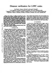
If LQi > 0, then xˆi = 0, else xˆi = 1. The decoder continues to pass these messages in each iteration until a preset maximum number of iterations is reached or the estimate x ˆ ∈ C, the set of all valid codewords. For a more detailed exposition of the MPA, see [12]. As with all linear codes, it is convenient to assume the all-zeros codeword as a reference vector for study. If a subset of variable nodes and check nodes is considered, members of this subset will be called the active nodes of a subgraph. By studying the local subgraph structure around each variable node, arguments can be made about the global graph structure. For example, bounds can be placed on the minimum distance of a code by only considering the local structure of a code [11]. Small subsets of non-zero bits which do not form a valid codeword but still cause the MPA decoder problems are well-documented in the literature and typically referred to as trapping sets (TS) [4]. A TS, x, is a length-n bit vector denoted by a pair (a, b), where a is the Hamming weight of the bit vector and b is the number of unsatisfied checks, i.e. the Hamming weight of the syndrome xHT . Alternatively, from a Tanner graph perspective, a TS could be defined as the a nonzero variable nodes of x and all of the check nodes connected by one edge to those a variable nodes. A valid codeword is a TS with b = 0. Two examples of TS, both extracted from a (96,48) code on MacKay’s website [13], are shown in Figure 1. The shaded check nodes, #4 for the (5, 1) TS and #2 and #11 for the (4, 2) TS, are the unsatisfied check nodes. A cycle of length c occurs when a path with c edges exists between a node and itself. There are no 4-cycles in this code, but there are many 6-cycles within the subgraphs of Figure 1. The essential intuition pointing to these as problematic for the decoder is that if a bits have sufficient noise to cause them to individually appear as soft 1’s, while the others in the subgraph are soft 0’s, the check nodes with which the a variable nodes connect will be satisfied, tending to reinforce the wrong state to the rest of the graph. Only the unsatisfied check(s) is a route through which messages come to reverse the apparent (incorrect) state.
(5,1) TS 4
5
6
22
7
28
12
87
13
14
46
93
92
(4,2) TS 1
2
2
11
31
3
33
23
38
39
38
Figure 1: A (5,1) and (4,2) TS subgraph
The number of edges within a TS, |ET S |, is determined by the number of variable nodes, a, and their degrees. |ET S | =
a X
dvi
(5)
i=1
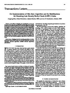
The number of check nodes participating in a dominant TS is most often given by |ET S | − b +b (6) 2 This equation assumes that all unsatisfied check (USC) nodes are connected to one variable node in the TS and all satisfied checks are connected to exactly two variable nodes from the TS. Subgraphs with these properties are referred to as elementary trapping sets in the literature [14]. Since any odd number of connections to TS bits will cause a check to be unsatisfied and any even number will cause the check to be satisfied, it is not guaranteed that all dominant TS are elementary. However, for dominant TS, i.e. those with small a and much smaller b, it is evident that given |ET S | edges to spend in creating an (a, b) TS, most edge permutations will produce dc = 2 satisfied checks and dc = 1 USC’s. Empirical evidence also supports this observation as is seen in compiled tables of TS shown in Section 3. The girth, g, of a graph is defined as the length of the shortest cycle and we assume this value to be g ≥ 6. This constraint is easily enforced when building low-density codes; 4-cycles are only present when two columns of H have 1’s in more than one common row. Now consider a tree obtained by traversing the graph breadth-first from a given variable node. This tree has alternating variable and check nodes in each tier of the tree. For this girth-constrained set of regular codes, a tree rooted at a variable node will guarantee all dv nodes in the first tier of variable nodes, in this case dv (dc − 1) = 15 nodes, will be distinct as illustrated in Figure 2. If |CT S | =
the root variable node in the tree is set to a ‘1’, then to satisfy all of the check nodes in the first tier of check nodes, an odd number of variable nodes under each of the dc check nodes in the first tier of variable nodes must be a ‘1.’ Since with high probability the dominant error events will correspond to elementary TS, we assume that exactly one variable node associated with each check node in the first tier is a ‘1.’ To enumerate all of these 1 + dv = 4-bit combinations we must consider all (dc − 1)dv = 125 combinations in one tree, and then take all n variable nodes as the root of a tree, which entails n(dc − 1)dv combinations for a general regular graph. The search method of Section 3 makes extensive use of these trees rooted at each variable node.
1
1
0000 00 1111 11 0000 1111 00 11 0000 1111 00 11 0000 1111 00 11 0000 1111 00 11 0000 1111 00 11 0000 1111 00 11 0000 1111 00 11 0000 00 1111 11 0000 1111 00 11 0000 1111 00 11
2
3
2 3 4 5 6 7 8 9 1011 1213141516 Figure 2: Tree showing first layer of check and variable nodes
3
Trapping Set Search Method (Step 1)
The key to an efficient search for problematic trapping sets (and low-weight codewords, which can be considered as an (a, 0) TS and will thus further not be differentiated from other TS) lies in significantly reducing the entire n-dimensional search space to focus on the only regions which could contain the dominant error events. The low-density structure of Tanner graphs for LDPC codes allows one to draw conclusions about the code’s global behavior by observing the local constraints within a few edges of each node. This allows a search algorithm that searches the space local to each variable node. To see how the local graph structure can limit our search space for dominant error events, consider two sets of length-n bit vectors with Hamming weight four. The first set, S1 , contains all such vectors: S1 = {x : wH (x) = 4}. The second set, S2 , consists of the constrained set of those four-bit combinations which are contained within the union of a variable root node and one variable node from each of the three branches in the first tier of variable nodes associated with that root node. When we consider only satisfied check nodes connected to two active variable
nodes, the number of active check or variable nodes in tier i is dv (dv − 1)i−1 . For example, the number of nodes in the first tier of variable nodes |V1 |, and the first tier of check nodes |C1 |, for {3, 6} codes, is |V1 | = |C1 | = 3. Now assign the variable nodes in the leftmost branch in the ith tier to set Vi1 and label these from left to right for all variable node sets in the ith tier. For example, in Figure 2, set V11 contains nodes 2-6, set V12 contains nodes 7-11, and set V13 contains nodes 12-16. We do the same for check node sets, and the first tier of check nodes would consist of only theTset C11 containing checks 1-3. Using this notation, set S2 can be defined as: v wH (V1i ) = 1 j = 1, . . . , n}. S2 = {x : (xj = 1) di=1 In a regular code there are dc − 1 elements satisfying wH (V1i ) = 1 for each i = 1, . . . , dv . Since we choose these elements from each of the V1i independently, there are (dc − 1)dv elements in S2 . For a regular {3, 6} code, dv + 1 = 4, so the elements of S2 are all 4-bit combinations, and these combinations of variable nodes will ensure that at least the three check nodes directly connected to the root variable node are satisfied. For example, if we choose the leftmost variable node in each branch of Figure 2, a member of the set S�2 would � be {v1 , v2 , v7 , v12 }. 96 = 3321960 and |S2 | = n(dc −1)dv = 12000. Consider a (96,48) {3, 6} code where |S1 | = 4 This example illustrates the large reduction in the number of vectors belonging to |S2 | as opposed to |S1 |, and thus results in a correspondingly much smaller search space for dominant error events. Notice the gap between the sizes of these two sets gets even larger as block length increases. The motivation for examining the smaller set of 4-bit combinations, |S2 |, above was to limit the number of directions in n-dimensional decoding space necessary to search for dominant error events. If a true ML decoder were available, a simple technique can be utilized to find the minimum distance of a code [15], which is similar to our problem of finding the low-weight TS spectrum for a code. The idea is to introduce a very unnatural noise, called an ‘error impulse,’ in a single bit position as input to the ML decoder. Unfortunately, the single-bit error impulse method cannot be used with the MPA to find dominant error events [16] mainly because the MPA’s objective is to perform a bit ML decision rule and not the vector ML rule. Typically when a large error impulse is input to one bit, the decoder will correctly decode the error until the impulse reaches a certain size where the channel input for that bit overrides the dv check messages and flips that bit while leaving all n − 1 other bits alone. Instead of the single-bit impulse, it makes more sense to apply a multi-bit error with a smaller impulse magnitude in each bit, as this would better simulate a typical high SNR noise realization. The choice of which bits to apply the impulse to is very important - they should be a subset of the bits of a minimum distance TS. A good candidate set of impulse bit locations is given by S2 . A multi-bit error impulse should appear as a more ‘natural’ noise to the MPA and the 4-bit combinations of S2 will be likely to get error impulses into multiple bits of a dominant TS. For example, suppose a minimum distance TS has a ‘1’ in its first four bits. If an error impulse ǫ1 were applied in all four of these positions, leaving the other n − 4 bits alone (i.e. the noise is −ǫ1 [1, 1, 1, 1, 0, . . . , 0]), would the message passing algorithm decode to this minimum distance TS? It cannot be guaranteed, but if the code block length is not too long, based on extensive empirical evidence, the decoder will decode to this nearby TS for sufficiently large ǫ1 . This MPA decoding behavior leads to the following theorem. Theorem 1 If g ≥ 6, in a {3, 6}-regular code, every (a, b) TS with a > b must contain at least one 4-bit combination from S2 among the a bits of the TS.
Proof 1 First notice that in a dominant TS, the TS variable nodes should not be connected to more than one unsatisfied check (USC). If a dv = 3 variable node were, then the 2 or 3 ‘good’ messages coming to that variable node should be enough to flip the bit, thus creating a variable node that is connected to 0 or 1 USC’s. Thus, for a dominant TS, we can assume that all variable nodes in the TS connected to USC’s are connected to only one USC. Now, take any variable node in the TS that is NOT connected to any USC’s (there will be a − b of these) and use it as a root node to unroll the graph to the first layer of variable nodes and notice that one of these (dc − 1)dv possible combinations of 4-bits (i.e. an element of S2 ) will all be within the a TS bits. As block length n increases, 4-bit impulses begin to behave like the single-bit impulses described above, where there exists a threshold ǫt such that for all impulse magnitudes below this threshold the decoder corrects the message and if ǫ1 > ǫt , then the decoder outputs a ‘1’ in the four bits with the impulse and sets the other n − 4 bits to ‘0’. For rate-1/2 {3, 6} codes this typically happens around n = 2000. One modification to partially avoid this is to scale the other n − 4 bits with another parameter, say γ. In other words instead of sending ‘1’ in the n − 4 noiseless bits, send 0 < γ < 1. This allows the ‘bad’ information from our four impulse bits to more thoroughly propagate further out into the Tanner graph and simultaneously lessens the magnitude of the ‘good’ messages coming in to correct the variable nodes where ǫ1 was applied. This method also loses effectiveness as n increases past 5000. For a still longer code, where say g ≥ 10, the 4-bit impulse method will generally fail unless modified again. To see why, consider the tree of Figure 3, and we will use the convention that the all-zeros message is sent and the LLR has the probability of a bit being a zero in the numerator, thus a ‘good’ message which works to correct a variable node will have a (+) sign and a ‘bad’ message which works to reinforce the error state will have a (-) sign. For a {3, 6} code, the six variable nodes at variable tier two of the tree (Vp in the Figure) will have four messages coming to them: the channel data Lc (+), Lr (−) from checks connected to variable nodes which have an ǫ1 error impulse input, and two Lr (+) messages coming from check nodes connected to noiseless variable nodes. Since the minimum magnitude of the messages which are incoming to the three check nodes neighboring one of the six Vp variable nodes is equal to γ, the three Lr messages will have roughly the same magnitude with belief propagation and exactly the same magnitude with the min-sum algorithm. Thus, the two positive Lr messages overpower the single negative Lr message, and the Lc = γ4Es /No message provides even more positive weight to our LQ marginal probability calculation. To get around this problem and force the decoder to return dominant error events, we find all possible v-nodes that are at variable tier two and connected to the dv (dv − 1) check nodes at check tier two of the tree. This will be dv (dv − 1)(dc − 1) = 30 variable nodes for a {3, 6} code. In these positions input an error impulse with a smaller magnitude than ǫ1 , but larger than that of the outside parameter +γ values. Call this second error impulse value ǫ2 . This extra deterministic noise causes the negative Lr messages floating down to variable node tier three of the tree to have a much larger magnitude than the positive Lr messages coming up, and this stronger ‘bad’ information is more likely to cause the decoder to fail on a dominant TS. To recap, for a {3, 6} code, the deterministic input to the decoder is now [1 − ǫ1 , 1 − ǫ1 , 1 − ǫ1 , 1 − ǫ1 , 1 − ǫ2 , . . . , 1 − ǫ2 , γ, . . . , γ]. It is important to have a definition of a TS which takes into account the entire history of the decoding process and not just the final state. This new definition will eliminate ambiguities that arise from the previous definition of a TS, which was based solely
1 − ǫ1
1 − ǫ1
Lr (−)
Vp Lr (+)
···
1 − ǫ2
Lr (+)
···
A total of dv (dv − 1)(dc − 1) variable nodes will have error impulses of ǫ2 . γ
Figure 3: Tree for Deterministic Noise Input
on the combinatorial properties of a bit vector. Since the entire decoding process involves many MPA iterations, a formal definition is necessary to locate where in this dynamic process the TS state was achieved. This definition will become important in Section 6.1. Definition 1 During the decoding process, a history of the hard decision, x ˆl , of the message estimate must be saved at each iteration l and if the maximum number of iterations Imax occurs and no valid codeword has been found, the TS will be defined as the x ˆl which satisfies min wH (ˆ xl HT ), where l = 1, . . . , Imax .
l
A practical example highlighting the power of this search method can be seen with some long {3, 6} codes proposed by Takeshita [17]. In two rate-1/2 codes, with n = 8192 and n = 16384, the search found many codewords at dH of 52 and 56 respectively. This was a great improvement upon the results returned from the Nearest-Nonzero Codeword Search of [16]. Table 1 gives the search parameters required to find error events for some larger codes. A total of 204 codewords with Hamming weight 24 were found in the Ramanujan [18] code, 3775 codewords with Hamming weight 52 in the Takeshita (8192,4096) code, and an estimated 4928 codewords with Hamming weight 56 in the Takeshita (16384,8192) code. This last estimate was determined by only searching the first 93 variable node trees, which took 12 hours, and then multiplying the number of codewords at Hamming weight 56 found up to that point (28 in this case) by (16384/93). Thus the time of 2112 compute-hours, running on an AMD Athlon 2.2 GHz 64-bit processor with 1 GByte RAM, is an
Code (4896,2448) (Ramanujan) (8192,4096) (Takeshita) (16384,8192)(Takeshita)
ǫ1 5 6.25 6.25
ǫ2 2 4 5
γ 0.4 0.45 0.4
Time (Hrs) 24 320 2112*
Table 1: Search Parameter Values, Eb /No = 6 dB, Max. 50 MPA Iterations estimate1 . This reasoning would not hold for most codes, but these algebraic constructions tend to have a regularity about them from the perspective of each local variable node tree. Although the large compute-times necessary for this method may seem impractical, for codes of this length, a simple Monte Carlo simulation would take much longer to find the error floor and it would not collect the dmin TS as this method does. For the three example codes above, the listed Hamming weights are believed to be their dmin . There could be more codewords of these Hamming weights, and it is possible that codewords of smaller weight exist, but this is unlikely and the multiplicity of these codewords found from our search is probably a tight lower bound on the true multiplicity. The argument here is the same used in [16], only this method appears to be more efficient for most types of low-density codes and has the advantage of also finding the dominant TS which are usually the cause of an LDPC code error floor. Another way to deal with longer codes is to grow the tree one level deeper, and apply the same ǫ1 to each of the variable nodes at the root, variable tier one, and variable tier two in Figure 3. For a {3, 6} code, this would give sets of 10 bits in which to apply the error impulse. The number of these 10-bit combinations for each root node is (dc − 1)dv (dc − 1)dv (dv −1) = 59 = 1953125, which clearly shows that this method is not nearly as efficient for long codes as it is for short codes. Still, the method will find an error floor, or at least a lower bound on Pf , much faster than standard Monte Carlo simulation. It is possible to take variations of these sets of bits; for example, if the code girth is at least 8, then all 6-bit combinations given by the root node, three variable nodes at tier one and the first two variable nodes at tier two (V21 , V22 ) are unique and make a good set of 6-bit error impulse candidates. The number of bits needed to form an error impulse capable of finding dominant TS is a function of n, k and girth. For larger n, more impulse bits are generally required. This method has been applied to many rate-1/2 codes with n at least 10000, and there was always a combination of parameters ǫ1 , ǫ2 , and γ which provided an enumeration of dominant TS and codewords, leading to the calculation of the error floor in much less time than what a standard Monte Carlo simulation would require.
3.1
Irregular Codes
Irregular codes can be constructed which require a lower Eb /No to reach the ‘waterfall’ threshold. Unfortunately these codes often suffer from higher error floors. The new search technique can efficiently determine what types of TS and codewords cause this bad high-SNR performance. 1
Throughout this paper, jobs requiring compute-times larger than 8-10 hours have been executed on a Linux cluster, where each node of the cluster has roughly the same computing power as the aforementioned platform. Thus, when large compute-times are listed, this can be considered the number of equivalent hours for a desktop computer.
The method of taking each of the n variable nodes and growing a tree from which we apply deterministic error impulses is the same. The major observation is that nearly all dominant TS and codewords in irregular codes contain most of their bits in the low-degree variable nodes. Most irregular code degree distributions contain many dv = 2 variable nodes, and these typically induce the low error floor. So, it makes sense to order the n variable nodes from smallest dv to largest and perform the search on the smallest (i.e. dv = 2) variable nodes first. In fact, for all irregular codes tested, the search for dominant TS can stop once trees have been constructed for all of the variable nodes with the smallest two dv ’s. Note that the number of bits which receive an error impulse is dependent on dv and will be 1 + dv if the tree is only grown down to the first variable node tier. The parameter values for ǫ1 , ǫ2 , and γ are also dependent on the variable node degree of the root in a given tree. For example, if the code has variable node degrees of [2 3 6 8], then the associated γ’s might be [0.3 0.3 0.4 0.45], i.e. the highest degree variable node of dv = 8 would have an error impulse in 9 bits, and thus it needs less help from the other n − 9 bits to cause an error, so its γ parameter can be set higher.
3.2
High-Rate Codes
LDPC codes of high rate contain check node degrees considerably larger than their lower rate counterparts. For example, in rate 0.8 regular {3, 15} codes, the 4-bit impulse method would require n(dc − 1)dv = n143 = 2744n decodings, much higher than the 125n decodings for {3, 6} codes. On a positive note, n can grow longer in these types of more densely-packed codes before the search requires the help of the extra ǫ2 noise. The search was applied to a group of codes proposed in [19] and succeeded in locating dominant TS and codewords. One code had column weights of 5 and 6 and row weights of 36. Instead of applying ǫ1 to a variable node from each of the V1i sets in variable tier one, which would require dv + 1 impulse bits, we instead pick a number less than dv , call it vnum , in this case 4, and choose all combinations of vnum variable node sets among the V1i sets. Assuming the check node degrees are all the same, the number of decodings |D| required using this method is given by (7).
|D| =
|dv | X i=1
|dvi |
�
dvi vnum
�
(dc − 1)vnum
(7)
where |dvi | denotes the number of variable nodes of degree i and |dv | denotes the number of different variable node degrees.
3.3
Search Parameter Selection
The choice of search parameters is very important in finding a sufficient list of dominant error events in a reasonable amount of compute time. The purpose of this section is to illustrate how the search method depends on the magnitude of the error impulse, ǫ1 , for the simple 4-bit impulse. Our example code, the PEG (1008, 504) {3, 6} code [13] will require n(dc − 1)dv = (1008)53 = 126000 total decodings in the search. Each decoding will attempt to recover the all-zero’s message from the deterministic decoder input of γ = 0.6 and ǫ1 varying over three values. The SNR parameter
Error Class (6,2) (4,2) (8,2) (10,2) (9,3) (7,3) (12,2) (5,3) (11,3) (10,4) (8,4) (6,4)
Multiplicity 5 6 3 3 27 57 1 21 2 5 8 21
d2E 12.47 12.43 12.79 14.29 19.93 22.27 19.61 29.32 79.34 70.70 77.49 55.89
|T S|Elem 5 6 3 3 27 57 1 21 2 5 7 21
Table 2: Dominant Error Event Table for (1008,504) PEG - Eb /No = 6 dB, ǫ1 = 3.0, γ = 0.6, 50 iterations will be Eb /No = 6 dB and a maximum of 50 BP iterations will be performed. The error impulse, ǫ1 , will take on the values 3, 3.5, and 4. Increasing ǫ1 increases the number of TS found while the mean number of iterations required for each decoding is also increased, which leads to the longer compute times needed to run the search program for larger ǫ1 . For example, if ǫ1 = 3, it might take 5 iterations on average to decode a message block. If ǫ1 is increased to 4, it might take a mean of 10 iterations to decode, thus causing the program to take twice as long, even though the total number of decodings, 126000, stays the same. The base case compute-time for this example code, with ǫ1 = 3, is slightly under 40 minutes. It appears that for most codes with n < 2000, there is an ǫ1 , call it ǫ∗1 , such that when ǫ1 is increased above this level, few meaningful error events are discovered beyond those which would be uncovered by using ǫ∗1 . So, by determining the probability of frame error contributed by those events found by running the search program with ǫ∗1 , we should have a reasonably tight lower bound on Pf for the code. How do we best find this ǫ∗1 ? There is probably no practical analytical solution to this question, but Tables 2 3 and 4 list the error events returned from the search using three different values of ǫ1 and will help illustrate the issue. The columns in the tables, from left to right, represent the TS class, multiplicity of that class, squared-Euclidean distance to the error threshold found by a deterministic noise directed towards the TS (averaged over each member of a specific TS class, this error threshold will be explained in Section 4), and the number of TS from this class that are elementary [14], meaning all unsatisfied checks have one edge connected to the TS bits. The major point to observe from the tables is that the first three rows, representing the most dominant error events, for this code TS of classes (6, 2), (4, 2), and (8, 2), are unchanged for each of the four search executions. This robustness to an uncertain ǫ∗1 is important for this method to be a viable solution, since ǫ∗1 will have to be iteratively estimated for a given code. Extensive Monte Carlo simulations with the nominal noise density in the higher SNR region verify that indeed the first three rows include the error events most likely to occur.
Error Class (6,2) (4,2) (8,2) (10,2) (12,2) (9,3) (7,3) (14,2) (11,3) (5,3) (10,4) (8,4) (6,4) (12,4) (7,5) (9,5) (11,5) (13,3) (15,3)
Multiplicity d2E |T S|Elem 5 12.47 5 6 12.43 6 3 12.79 3 4 14.26 4 4 16.08 4 89 22.20 88 97 23.58 97 2 17.74 2 8 39.39 8 90 33.90 90 30 64.40 29 82 56.71 82 127 55.57 127 2 45.85 0 15 82.75 15 4 98.12 4 5 120.52 4 1 159.03 0 1 183.49 1
Table 3: Dominant Error Event Table for (1008,504) PEG - Eb /No = 6 dB, ǫ1 = 3.5, γ = 0.6, 50 iterations
Error Class (6,2) (4,2) (8,2) (10,2) (12,2) (9,3) (7,3) (14,2) (11,3) (16,2) (13,3) (5,3) (10,4) (8,4) (12,4) (6,4) (9,5) (11,5) (14,4) (7,5) (15,3) (13,5) (15,5)
Multiplicity 5 6 3 4 6 113 110 3 49 1 9 104 124 469 12 384 104 10 3 176 3 1 1
d2E |T S|Elem 12.47 5 12.43 6 12.79 3 14.26 4 16.64 6 21.29 111 26.59 109 17.73 3 23.38 48 19.36 1 52.08 9 35.88 104 48.36 116 45.96 466 94.28 5 54.95 383 90.18 100 100.19 7 97.89 1 80.71 172 124.18 0 159.03 1 183.49 0
Table 4: Dominant Error Event Table for (1008,504) PEG - Eb /No = 6 dB, ǫ1 = 4.0, γ = 0.6, 50 iterations
4
Locating TS Error Boundary (Step 2)
Once a list of potential dominant error events has been compiled, it is not a simple task to determine which of these bit vectors will cause the decoder the most trouble. For an ML decoder this is not an issue because the Hamming weight, wp H , is enough information to determine the two-codeword error probability: P (x1 → x2 ) = Q( 2wH Es /No). For a TS, it is possible to determine the error contribution of a certain bit vector by either conditioning the probability of error on the magnitude of the noise in the direction of the TS bits [4] or by using a mean-shifting IS procedure [9]. Both of these methods require a simulation with at least a few thousand noisy messages per SNR to get an accurate measurement of the Pf contributed by the TS in question. The idea proposed here is to send a deterministic noise in the direction of the TS bits and let the decoder tell us the magnitude of noise necessary to cross from the correct decoding region into the error region and use this information to quickly determine relative error performance between different TS, not necessarily of different (a, b) type. This method only maps out the point of the error boundary which is along the line connecting the all-ones point in n-dimensional signal space with the point on the n-dimensional hypercube associated with the given TS. It requires only p decodings to find this point of the error boundary with accuracy (lmax − lmin )/2p since a binary search, as described below, has complexity O(log L), where L = 2p is the number of quantization bins in between lmax , the largest magnitude in a dimension where a TS bit resides, and lmin = 1, which would be on the error boundary if the TS were an actual codeword. lmax = 3.5 is the value used in this research. The procedure to locate the error boundary is to first input the vector y = [1 − I(1)ǫ, 1 − I(2)ǫ, . . . , 1 − I(n)ǫ] to the decoder, where I(i) is the indicator function for whether the ith bit belongs to the TS and the magnitude of ǫ, call it ǫ1 , is (lmin + lmax )/2. If the decoder corrects this deterministic error input, then for the second iteration, and in general for the ith iteration, update ǫi = ǫi−1 + (lmax − lmin )/2i and apply this to the decoder input. If the first input vector resulted in an error, then set ǫi = ǫi−1 − (lmax − lmin )/2i . This process will be repeated p times, which tells us to within (lmax − lmin )/2p how close the error boundary is, requiring only p decodings. p = 10 is used in this research and should be more than adequate for most purposes. All non-codeword TS, since they have at least one unsatisfied check (USC), should have a distance to the error boundary that is at least as large as the distance to a wH = a codeword error boundary. Finding the error contribution of a specific TS is analogous to the two-codeword problem, except the error region is much more complicated than the half-space decision region resulting from the two-codeword problem. The situation is depicted in Figure 4 where we assume a (4, 2) TS exists among the first 4 bits of the n-length bit vector. Consider the n − 1 dimensional plane bisecting the line joining the 1 vector (all-zeros codeword) and the (-1,-1,-1,-1,1,...,1) TS; this plane would represent a half-space boundary if the TS were actually a codeword and the decoder were ML. The arrow starting at the point 1 (the signal space coordinates of codeword 0) and directed towards the TS shows where the error region begins. The shape of the error region is very complicated and this two-dimensional figure does not accurately represent its true shape, but it makes intuitive sense that the nearest point in the error region should be in the direction of the bits involved in the TS. Table 5 lists the dominant TS found with the search for a (504,252) regular {3, 6} code with girth eight [3]. The parameters of the search were set as follows: ǫ1 = 3.6, γ = 0.8, 50 iterations,
E
(1,1,. . .,1) (1-ǫ,1-ǫ,1-ǫ,1-ǫ,1,. . .,1)
√
(-1,-1,-1,-1,1,. . .,1) √ n
n
(0,0,. . .,0) Figure 4: Deterministic Error in TS Direction
Eb /No = 5 dB. The column labeled d2E denotes the average Euclidean-squared distance to the error boundary for the TS class in that row. For example, if a deterministic noise impulse with magnitude ǫ were applied in each of the a bits of an (a, b) = (10, 2) TS and the decoder switched from correctly decoding to an error at ǫ = 1.5, then d2E = aǫ2 = 10(1.5)2 = 22.5. The rows are ordered by dominance, where the minimum d2E among all TS of a class determines dominance. For example, the (11,3) TS on average have a larger d2E (23.3 in this case) than the (9,3) TS, which has an average of 20.7, but the minimum d2E among the 20 (11,3) TS is less than the minimum among the 186 (9,3) TS. This behavior is in contrast to valid codewords, where all codewords with a given wH will have the same error contribution in the two-codeword problem. The (10, 2) 2 TS class had a member with the smallest d2E among all TS found p for this code. Knowing dE does not tell us exactly what contribution a TS gives to Pf , but Q( 2d2E Es /No) does approximate this contribution to within a couple orders of magnitude. One way to get more confidence in the validity of using d2E as a criteria to establish which TS are most dominant is to simulate a large number of noisy message frames using the nominal Gaussian noise density at a higher SNR and tabulating which TS classes these errors fall into. This is done for the PEG (1008,504) code at Eb /No = 4.0 dB and the results are in direct correlation with what is expected from the d2E values computed with our deterministic noise impulse (See Table 4 for dominant TS of this code). This code has five (6,2) TS which dominate and two of them have a d2E smaller than the rest (at 4.0 dB), and these specific TS are indeed much more likely to occur with the nominal noise density. Two (8,2) TS are also very dominant. Table 6 shows all of the TS which had more than one error with the nominal noise density. 6(10)8 trials at Eb /No = 4.0 dB were performed and a total of 85 errors were recorded. The value in column two of Table 6 denotes the number of times the five most dominant error events occur. All but five of these 85 total errors were from TS that were represented in the list in Table 4 obtained with the new search method.
Error Class (10,2) (12,2) (11,3) (9,3) (10,4) (13,3) (8,4) (7,3) (12,4) (6,4) (9,5) (7,5) (11,5) (5,3)
Multiplicity 22 5 20 186 46 4 303 106 3 1178 15 41 1 24
d2E 15.01 15.87 23.29 20.68 28.64 19.76 27.78 26.09 41.87 41.14 27.99 32.92 26.82 41.30
|T S|Elem 22 5 17 186 40 3 300 106 2 1178 13 41 0 24
Table 5: Dominant Error Event Table for (504,252) {3, 6} Code - Eb /No = 6 dB, ǫ1 = 3.5, γ = 0.6, 50 iterations
TS (6, 2)1 (6, 2)2 (8, 2)1 (8, 2)2 (10, 2)1
#Errors 28 20 11 8 3
d2E at 4.0 dB 14.31 14.36 14.35 14.46 15.54
Table 6: Monte Carlo Verification of d2E
5
Importance Sampling (IS) (Step 3)
In IS, we statistically bias the received realizations in a manner that produces more errors [5, 6, 7]. Instead of incrementing by one for each error event (Ie ), as for a traditional Monte Carlo (MC) simulation, a ‘weight’ is accumulated for each error to restore an unbiased estimate of Pf . This strategy, if done correctly, will lead to a greatly reduced variance of the estimate compared to standard MC. f ∗ (y) denotes the (IS) biasing density and it is incorporated into the MC estimate as follows: Pf , E[Ie (y)] Z = Ie (y)f (y)dy ℜn Z f (y) ∗ = Ie (y) ∗ f (y)dy f (y) ℜn = E∗ [Ie (y)w(y)] This gives an alternate sampling estimator L
1X Ie (yl )w(yl ) PˆfIS = L l=1
(8)
L realizations yl are generated according to f ∗ (y), the biased density. If yl lands in the error l) region then the weight function, w(yl ) = ff∗(y , is accumulated to find the estimate of Pf . MC (yl ) can be seen as a special case of this more general procedure, with f ∗ (y) = f (y). PˆfIS is unbiased and has a variance given by
V ar[PˆfIS ] = E∗ [
L 1 X ( Ie (yl )w(yl ))2 ] − Pf2 L2 l=1
1 (LE∗ [Ie2 (y)w 2 (y)] + L(L − 1)Pf2 ) − Pf2 L2 E∗ [Ie (y)w 2(y)] − Pf2 = L E[Ie (y)w(y)] − Pf2 = L R w(y)f (y)dy − Pf2 =E L =
(9)
Notice that because f ∗ (y) is in the denominator of w(y), it must be non-zero over the error region E, else V ar[PˆfIS ] is unbounded. The key quantity here is the first term on the RHS of the last line in (9). For the IS method to offer a smaller variance than MC, this quantity must be less
than Pf which appears as the first term on the RHS of V ar[PˆfM C ]. We will denote this term as V and estimate it on-line using MC, where the samples are taken from f ∗ (y). Vˆ
=
1 L
L P
w(yl )2
(10)
l=1
Both Vˆ and PˆfIS rely on the same samples, yl , and this circular dependence means that if we are underestimating Pf , then we are likely underestimating V . Vˆ can give us some confidence in PˆfIS , but the simulator must make sure that PˆfIS passes several consistency checks first. It will most often be the case that Pˆf is being underestimated. One check is employing the sphere packing bound [20], which can be used as a very loose lower bound that no code could possibly exceed. One benefit of tracking Vˆ is that if it indicates a poor estimate, then Pˆf is definitely not accurate, but the converse is not true. Using an f ∗ with the same properties as the nominal f , except for a shifted mean to center the new density at the error boundary, has been shown to provide the smallest V ar[PˆfIS ] in the two-codeword problem [7, 5] and large deviations theory [21] also suggests that mean-shifting to the nearest error regions in n-dimensional signal space should provide the optimal f ∗ . The f ∗ proposed for determining error performance of LDPC codes is based on a weighted sum of mean-shifted fi∗ densities, where there are M nearby error events used to form f ∗ . M 1 |y − µi |2 1 X exp − f (y) = M i=1 (2πσ 2 )n/2 2σ 2 ∗
(11)
The µi are n-bit vectors with zeros in all places except for ones in the a bits of an (a, b) dominant TS or the wH bits of a low-weight codeword. The choice of using a magnitude of ‘1’ in the a TS bit positions is probably not the most efficient. When shifting towards valid codewords, ‘1’ is the optimal value for this mean-shifted f ∗ [7]. The distance to the error boundary for a TS, as found in step two of our procedure, always has a magnitude ≥ 1 in the a bit positions of the TS. So, if mean-shifting to the boundary of the error region is the most efficient IS procedure, then this shift value should be used instead of ‘1’. Since the two-codeword error regions of TS are not in the shape of a half-space, this argument is not quite correct, so although a more efficient simulation can be performed by increasing the shift value to have a magnitude larger than one, care must be used to not over bias the shift point, which will return a PˆfIS which is too small [6]. This weighted-sum IS density should catch many of the ‘inbred’ TS which were not explicitly caught in the initial TS search phase, but which share many bits with the TS vectors that were found and thus are ‘close by’ in n-dimensional decoding space. The weighted-sum f ∗ IS density should work best at moderate SNR where many error events contribute to the error floor. At the highest SNR’s of interest, large deviations theory suggests that only the nearest error events in n-dimensional decoding space contribute to Pf [22]. If there are a small number of these nearest events, then it is appropriate to break E up into α regions Ei, i = 1, . . . , α corresponding to each of the minimum distance error events. α is the total number of these minimum distance events. An example of this technique used on a {4, 8} code will be given in Section 7.
6
Error Floor Estimation Procedure
Our procedure consists of three steps which all make use of the decoding algorithm to map out the n-dimensional region of E and estimate Pf . Since this region is very dependent on the particular decoding algorithm and its actual implementation details, e.g. fixed-point or full double-precision values for messages, it is imperative to make use of the specific decoder to determine E. The first step uses the search method proposed in [3] and expanded upon in Section 3 to obtain a list of dominate error events. This list is dependent on the decoding algorithm since certain TS might be more problematic for say the full belief propagation implementation as opposed to the min-sum approximation. The size of the list is also a function of the parameters ǫ1 , ǫ2 , γ, and Eb /No . It is important to choose these parameters to find all of the dominant error events, while still keeping the average number of iterations per decoding as small as possible to avoid wasting computing time. We will see in some examples that as long as all of the minimum distance error events are included in this list, it is possible to miss some of the moderately dominant error events and still get an accurate estimate of Pf . This is an important benefit over the method which breaks up the error region into separate pieces for each possible bit vector as proposed in [4, 9], where the estimate of Pf will almost assuredly be below the true value, as it is nearly impossible to guarantee all important error events have been accounted for, especially for longer and higher rate codes. To expand on this, consider a simple toy example where there are six dominant error regions and our initial list contains all but one of these. Figure 5 shows the error region surrounding the all-zeros codeword. The small, grey filled circles between the all-ones point in n-dimensional space and the nearest error regions are the mean-shift points in f ∗ . The single white-filled circle in front of E1 represents the dominant error event which was not accounted for in the initial list obtained with the search from step one of the three-step procedure. Notice that the two mean-shift points towards the regions E2 and E6 are ‘close enough’ in n-dimensional space to have a high probability of landing some f2∗ or f6∗ noise realizations in E1 . This will allow the E1 contribution to be included in the total Pf estimate. If, on the other hand, there are Ei such that no mean-shift points are near enough to these regions to have significant probability of producing noise realizations in them, then PˆfIS will with high probability (essentially the same probability of not getting a hit in Ei ) underestimate Pf by the amount of the error probability that lies in Ei . So the paradox is that even though PˆfIS is unbiased, it can with high probability underestimate the true Pf when using this particular f ∗ . To form an f ∗ which adequately covers the error region without needlessly including too many shift points which are unlikely to offer any error region hits and only serve to complicate f ∗ , we make use of the d2E values returned from stage two. The third column of Table 5 lists the d2E values for a (504,252) {3, 6} girth eight LDPC code [3]. From this column, it can be seen that the (10,2) and (12,2) TS are the most dominant error events. The (6,4) TS have a very large multiplicity of at least 1178, but with an average d2E of 41.14, they don’t contribute much to Pf at higher SNR. Still, there are some (6,4) TS with much smaller d2E than the average over this class, so some of these should be included in f ∗ . Thus, a good strategy would be to order the entire list provided by the search and pick the M TS with the smallest d2E to include in f ∗ for the third step of the procedure. M will be based on the parameters n and k of the code as well as the size of the initial TS list. A larger M will provide a more accurate estimate of Pf , but will require more total noisy
E3 E2
[1, · · · , 1]
E1
E4
E5 E6
Figure 5: IS mean-shifting to cover error region
message decodings if we use a fixed number of decodings P for each mean-shifted fi∗ . The final step of our procedure takes the M error events with the smallest d2E and forms a weighted sum of mean-shift fi∗ densities for f ∗ (11). Equation (12) below confirms that deterministically generating P realizations for each of our M fi∗ densities will form a valid, unbiased, PˆfIS . M P 1 X 1 X Ie (y)f (y) ˆ PfIS = M M m=1 P l=1 1 P fp∗ (y) M
(12)
p=1
The expected value is M M Z ∗ X X 1 I (y)f (y) 1 f (y)fm (y) e ˆ E[PfIS ] = E[ M ]= dy M P P M m=1 M m=1 1 1 ∗ ∗ fp (y) fp (y) E M M p=1
1 = M
Z f (y) E
1 M
M P
m=1 M P
p=1
p=1
∗ fm (y)
fp∗ (y)
dy =
Z
f (y)dy = Pf
E
One implementation issue which must be addressed concerns the numerical accuracy of the weight function calculation. Any computer will evaluate ex = 0 when x < −N for some positive N. When the block length is large or the SNR is high, all of the terms in f ∗ could equate to zero, giving a weight of x0 = ∞. To avoid this, a very small constant term can be added in both
the f (y) and f ∗ (y) distributions which will, with high probability, ensure that |x| < N while not affecting the value of the weight function. The constant term ψ is added in the second line of the following equation: (2πσ 2 )n/2 w(y) = (2πσ 2 )n/2
1 M
m=1
2 exp − (y−1) 2 2σ
exp ψ = = M P (y−1+µm )2 1 exp − 2σ2 exp ψ M m=1
If ψ is chosen to be
n , 2
2
2
exp − (y−1) 2σ2 = M P (y−1+µm )2 exp − 2σ2 1 M
1 M
+ ψ) exp(− (y−1) 2σ2 M P 2 m) exp(− (y−1+µ + ψ) 2σ2
m=1
2
exp − (y−1) 2σ2 M P 2 m) exp − (y−1+µ 2σ2
m=1
then the argument in the exponent of the P term in the denominator
corresponding to the fi∗ centered about the ith shift point will be −( P n 2 i=1 (ni ) 2σ2
(13)
σ2
n 2 i=1 (ni ) 2σ2
− n2 ). Since the
term is a scaled χ2 random variable with E[z] = n 2σ2 = n2 , all M terms in the z = denominator of the weight function will be zero only if all of the χ2 random variables fall more than N from their mean, which is highly unlikely, especially for large n and high SNR.
6.1
New Error Events
One way to gain insight into how well the initial list contains important error events is to keep track of all errors which occur during the IS simulation, and call these ‘hits.’ When a hit occurs, we see if this TS is the same as the bit string towards which we biased for that noise realization. If it is, this will be called an ‘intended hit.’ As SNR increases, the number of intended hits should approach the number of hits, because the noise ‘clouds’ are more concentrated and less likely to stray from the error region near the shift point. If the decoder does not converge to the all-zeros codeword after the maximum number of iterations and a new TS, as defined by Definition 1, occurs during the decoding process which is not among the initial M shift points, then add this new error event to a cumulative list. Continue making this list of new error events and their frequency of occurrence. The list of new error events will gauge how thorough the initial list of TS covers the error region. Because noise realizations have occurred in the new error regions associated with the new error events, these regions are effectively considered in PˆfIS , even though they weren’t included in the M shift-points ahead of time. The new TS should contain many bits in common with some of the more dominant TS returned from the search procedure of step one. The M shift points can be adaptively increased as new events with small d2E are discovered. If the parameters used in the search of step one are chosen wisely, then the initial list of shift points should adequately cover the error region and the list of new error events will be small. It is common for the empirical variance, (10), to underestimate the true variance in the highSNR region where the noise clouds are small. This is because almost all of the hits are intended hits, so the noise realizations don’t venture towards new error regions, where hits are likely to cause a large w(y). So, in the high-SNR region, when the initial TS list excludes some dominant error events, these regions are being ignored in Pˆf IS and Vˆ . For example, consider a standard Monte Carlo simulation. At high SNR, we explore the n-dimensional error region centered about the all-ones point (all-zeros codeword) with 107 noisy messages. Let the true Pf be 10−8 at
7
this SNR. Thus with probability (1 − 10−8 )10 = 0.9048 we would not get any hits in 107 trials, resulting in an estimate of Pˆf M C = 0 and an empirical variance also equal to zero. Now, using (11), imagine placing the initial point of reference at one of the M shift points located between the all-ones point and the dominant error event boundaries. Since most of the noise realizations fall much closer to the intended error region, there will be many more hits in this error region and the error contribution of at least those TS and codewords among the list of M shift points will be counted. Still, for all but relatively short codes, this list will be incomplete and a large Vˆ could be obtained by having one or more noise realizations land in error regions not included among the M points in the initial list that are closer to the all-ones vector than any of our shift points. This will produce a weight greater than one, which will significantly increase Vˆ . Although this will give a large Vˆ , it is still better to know that this previously undiscovered error event exists. The alternative situation, where no new error events are discovered, will produce a small Vˆ , but this is reminiscent of the Monte Carlo example above where the regions of E not associated with our M shift points are ignored. IS is no magical tool, and it really only helps when we know ahead of time (steps one and two of the procedure) where the nearest error regions are. What we gain from using (11) as our IS f ∗ is a significant reduction in the number of samples needed to get a good estimate of Pf compared to the method of finding the Pf contributed by each individual error event as detailed in [9, 4]. There is also a better chance of accounting for the Pf contributed by those error events which were not explicitly enumerated with the search of step one in our procedure, but are ‘close by’ in n-dimensional decoding space to some of the vectors that were in the list. Still, it must be stressed that IS is a ‘dumb’ procedure that helps when we already have a very good list of dominant TS and codewords for the given code.
6.2
Complexity
It is difficult to attach a measure of complexity to our entire procedure. Traditionally, a ‘gain’ metric is measured in an IS simulation, usually a ratio of the number of samples required to achieve a certain variance for Pˆf using Monte Carlo versus applying IS. This metric is essentially useless when applying IS to the analysis of the error performance of large LDPC block codes. The online variance estimator of (10) which is typically used to determine the number of samples required to achieve a variance comparable to Monte Carlo for a given SNR is, as outlined above, not reliable. Another often overlooked aspect of using IS to simulate decoding errors is the increase in the mean number of iterations required to decode when f ∗ causes most noise realizations to fall near and in the error region, thus requiring the decoder to ‘work harder’ to find a valid codeword. When the list of mean-shift candidates in f ∗ is large, the calculation of the weight function is also time consuming. So, ultimately, the best choice of metric for measuring complexity will be the less elegant - but more accurate - total compute-time required to run the IS simulation. This will incorporate the total number of noise samples, the extra iterations required for the MPA to decode shifted-noise realizations, and the weight function calculation. To measure complexity of the entire three-step process, also include the time required to search for and determine relative dominance of the initial list of TS from steps one and two.
7
Simulation Results
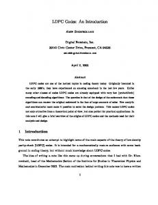
We now compare the error performance analysis results obtained from the three-step procedure with a standard Monte Carlo estimate to see if the results concur. The Cole (504,252) code [3] with girth eight and a progressive edge growth [23] code on the MacKay website [13] will be used as a test case. Figure 6 has Monte Carlo data points up to Eb /No = 5 dB for both codes. The highest SNR point at 5 dB for the Cole code involved (3.15)109 trials and 13 errors were collected, so PˆfM C is not very accurate. It took about 6000 compute-hours on the cluster to obtain this point. The IS data for both codes, while slightly underestimating the true Pf , only required 12 minutes to obtain the dominant TS list in step one, negligible time to determine d2E for step two, and 2 hours for the actual IS simulation. PEG (504, 252) versus Cole (504,252)
0
10
Cole MC MacKay MC Cole IS MacKay IS −5
FER
10
−10
10
−15
10
2
3
4
5
6
7
E /N (dB) b o
Figure 6: Comparison of (504,252) codes The phenomenon of underestimating Pf using the f ∗ of step three is the most troublesome weakness in our procedure. Figure 7 shows three curves representing the IS estimate of the (1008,504) Cole code. All three use the same f ∗ , but the number of samples per SNR varies among 39000, 390000, and (3.9)106. As more trials are performed, more of the error region gets explored, thus increasing Pˆf IS . This effect is strongest at lower SNR where the noise clouds are larger and our f ∗ is less like the ‘optimal’ f ∗ . In all of the following results, a maximum of 50 MPA iterations were performed in decoding. Table 7 lists the parameters used in the search phase of our procedure for a number of different codes. A value of 1 − γ in the ǫ2 column means ǫ2 was essentially not used and only the 4-bit impulse with magnitude ǫ1 was used, and the rest of the n − 4 bits were scaled by γ. ǫ2 is usually only required for larger codes. The column labeled ‘Mean d2E ’ in Table 8 is calculated over all |EE| of the error events, not just the ones that fall below the threshold, d2E < d2ET . The ‘Time’ column in Table 9 is on an AMD Athlon 2.2 GHz processor with 1 GByte RAM.
Code (504,252) (Cole) (504,252) PEG (Hu) (603,301) Irregular (Dinoi) (1008,504) (Cole) (1008,504) PEG (Hu) (2640,1320) (Margulis) (4896,2448) (Ramanujan) (1000,500) {4, 8} (MacKay)
ǫ1 3.6 3.6 3.5 4 4 5 5 2.5
ǫ2 1−γ 1−γ 1−γ 1−γ 1−γ 1−γ 2 1−γ
γ 0.8 0.8 0.3 0.7 0.7 0.3 0.4 0.4
Eb /No (dB) Time (Hrs) 5 0.2 5 0.2 5 1.5 7 1.2 7 1.2 6 8.2 6 24.0 8 1.7
Table 7: Step one parameter values
Code (504,252) (Cole) (504,252) PEG (Hu) (603,301) Irregular (Dinoi) (1008,504) (Cole) (1008,504) PEG (Hu) (2640,1320) (Margulis) (4896,2448) (Ramanujan) (1000,500) {4, 8} (MacKay)
|EE| 578 1954 10760 750 1700 2640 204 119
d2ET 29 60 60 20
|EE|