Image-based 3D modeling is an easy and cheap solution ... registration of texture patches and triangle faces in image- .... Gradient domain blending [3,12, 13].
Proceedings of 2010 IEEE 17th International Conference on Image Processing
September 26-29, 2010, Hong Kong
A General Texture Mapping Framework for Image-based 3D Modeling Lin Xu, Eric Li, Jianguo Li, Yurong Chen, Yimin Zhang {lin.x.xu, eric.q.li, jianguo.li, yurong.chen, yimin.zhang}@intel.com Intel Labs China ABSTRACT This paper presents a general texture mapping framework for image-based 3D modeling. It aims to generating seamless texture map for 3D model created by real-world photos under uncontrolled environment. Our proposed method addresses two challenging problems: 1) texture discontinuity due to system error in 3D modeling from selfcalibration; 2) color/lighting difference among images due to real-world uncontrolled environments. The general framework contains two stages to resolve these problems. The first stage globally optimizes the registration of texture patches and triangle faces with Markov Random Field (MRF) to optimize texture mosaic. The second stage does local radiometric correction to adjust color difference between texture patches and then blend texture boundaries to improve color continuity. The proposed method is evaluated on several 3D models by image-based 3D modeling, and demonstrates promising results. Index Terms— texture mapping, image reconstruction, image color analysis, Illumination 1. INTRODUCTION Image-based 3D modeling is an easy and cheap solution for amateurs to create 3D model compared to laser scanning method. The technique becomes more mature in recent years. Meanwhile, texture mapping for image-based 3D modeling becomes important. It is a more challenging problem than that in laser scanning. There are two basic differences between texture mapping in image-based models and laser scanning models. First, there is relatively larger system error in image-based 3D modeling compared to that in laser scanning techniques. This will lead to missregistration of texture patches and triangle faces in imagebased 3D models, and further lead to texture fragments. Second, the textures are usually captured in a relatively professional (controlled) environment for laser scanning method, while image-based 3D modeling tends to capture photos anywhere and anytime. This usually makes the significant radiometric difference among images. There are several existing works for 3D models texture mapping. Generally, these works can be classified into three categories. First, the image-blending technique has been
978-1-4244-7993-1/10/$26.00 ©2010 IEEE
2713
used for texture mapping when there is very little radiometric difference. It tried to eliminate seams among adjacent texture patches through image-blending [1] method. A representative work is the texture mapping in 3DSOM system [2] which works under a professional controlled lighting environment. It applies a two-band blending technique to keep both high frequency edge information and low-frequency general information. However, the 3DSOM system works under a strictly controlled environment. It cannot be applied to real-world pictures with relatively large color difference. Second, texture patch registration optimization is widely used to alleviate small texture fragments. Straightforward best-fit based registration method will cause scattered texture fragment with noticeable color discontinuity. An impressing improvement is to introduce Markov Random Field (MRF) [3][4] to optimize the texture mosaic, which considers both image visibility and color continuity to optimize the registration of texture patches and triangle meshes. However, when there are larger radiometric difference among images (especially true for real-world photos), the MRF optimization is not effective enough to mask the color difference among different texture fragments. Third, there are some works on global radiometric (color/lighting) correction for different photos in texture mapping [5, 6]. This is a typical problem in computational photography. But so far, most of them need manually point out the region to adjust. And more important, for real-world photos taken in uncontrolled environment, the global radiometric correction is not that effective since the texture mapping focuses more on local continuity between adjacent texture fragments. In this paper, we propose a general texture mapping framework for image-based 3D modeling, which resolves two challenging problems from two perspectives. First, it adopts MRF-based optimization to realize global registration of texture patches and triangle faces. This registration can minimize texture fragments. Second, we do local radiometric correction among pieces of texture patches to minimize color difference, seams and blurs. The rest of the paper is organized as follows. In Section 2, we introduce the general texture mapping framework for global registration and local radiometric correction. Section 3 evaluates the proposed method on several real-world
ICIP 2010
image-based 3D models. Conclusions are drawn in Section
4.
Calibrated Images
Image to Patch Assignment
Color Correction
Texture Atlas Generation
3D Model
Patch Optimization
Image Blending
Textured Model
Geometric part Radiometric part Figure 1. Texture mapping flowchart
2. GENERAL TEXTURE MAP FRAMEWORK In this section we present a general texture mapping framework for image-based 3D models. The flowchart of our framework consists of five steps, as shown in Figure 1. The inputs are a 3D model M, which consists of m faces, denoted as F={f1,…,fm}, and n calibrated images I1,…, In. 2.1 Image to patch assignment In the first step, we decide the relationship between images and the 3D model with the calibration matrices P1,…,Pn. Before projecting 3D points to 2D images, it is necessary to define visible faces in the 3D model from each camera. We adopt the method in [7], which is an efficient hidden point removal algorithm based on convex hull [8]. The central point of each face is used as the input in the algorithm to determine the visibility for each face. And then the visible 3D faces can be projected onto images with the projection matrix Pi. For the radiometric correction, we also calculate the color difference between every visible image on adjacent faces, which will be used in the following steps. 2.2 Patch optimization With relationship between images and patches, in this step, we assign each face of the mesh to one of the input views in which it is visible. The labeling process is to find a best set of l1,…,lm (a labeling vector ܮൌ ሼ݈ͳ ǡ ǥ ǡ ݈݉ ሽ א ሼͳǡ ǥ ǡ ݊ሽ ), which enables the best visual quality and the smallest edge color difference between adjacent faces. Similar to [3], we mostly follow the MRF framework with a few improvements. The energy function is composed from two terms. It can be expressed as: (1) ܧሺܮሻ ൌ �ܧሺܮሻ ¬ ܧሺܮሻ The first term �ܧሺܮሻ is the energy term corresponding to the quality of visual details. Here we define the connected faces with the same label as one texture fragment. We use the angle between the viewing direction Oi of the corresponding view and the face normal as the cost value: �ܧሺܮሻ ൌ െ σ (2) ൌͳ ൏ ܲ ሺ݂݅ ሻǡ ܱ݅ The second term ܧሺܮሻ corresponds to the color continuity. Let us note the edge, shared by two adjacent faces ݂݅ and ݂݆ , as ݁݅ǡ݆ . The color difference of this edge can be measured as:
2714
(3) ݃ ǡ ൌ ݀ ൫ܲ݅ ሺݔሻǡ ݆ܲ ሺݔሻ൯ ݔ In (3), Pi(x) represents the projected point from 3D model to image i, and ݀ሺǤ ǡ Ǥ ሻis a Euclidean distance in RGB color space. If the texture mosaic aims to minimize the color difference, then the second term will be written as: ܧሺܮሻ ൌ െ σ ǡ אɂ ݃݁݅ǡ݆ (4) where is the assemble of all edges in 3D mesh. Therefore, the overall energy function can be rewritten as: ܧሺܮሻ ൌ െሺσ݉ ݅ൌͳ ൏ ܲ ሺ݂݅ ሻǡ � σ ǡ אɂ ݃݁ ݅ǡ݆ ሻ (5) Function (5) is a typical target energy of a pairwise discrete-labeled MRF. An efficient solution to this problem is multi-way Graph Cuts (GC) [11]. Though MRF optimization minimizes visibility seams textured from different fragments, there are some isolated labels whose neighbor faces are from another fragment. This is mainly due to the inaccuracy of face normal in the 3D model, thereby degrading the overall accuracy of MRF optimization. To resolve this problem, we propose a face filtering method. Given a face fi, we calculate the maximum count of its neighboring faces which have the same fragment label. If this number is above a threshold (3 in our experiment), we change its face label to l. The purpose of this filtering method is to maximize the continuity of texture fragment. The procedure is iterated multiple times for all the faces until there is no isolated fragment.
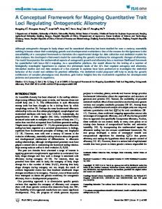
(a) (b) Figure 2. Comparison between before (a) and after (b) filtering optimization. Figure 2 shows the advantage optimization. The temple 3D model dataset: templeRing) is reconstructed developed multi-view stereo method.
of our filtering (from Middlebury using an in-house Figure 2(a) is the
result after MRF optimization. There are many disjointed fragments on the pillars. After filtering optimization in Figure 2(b), most of the fragments are continuous which means that the proposed method can greatly reduce the number of isolated faces. 2.3 Color correction After patch optimization, a texture mosaic with least color discontinuities is obtained. But we can still notice discrete hue boundaries between faces which come from different views. The discrepancy mainly comes from the illumination conditions, non-linear camera capturing system and the object material effect. Even with uniform lighting conditions, these discontinuities still exists. Image blending is one common technique which is widely used in [2][3][4] to visually reduce the discontinuous seams. However, it cannot entirely eliminate the color difference and lighting condition effect. Therefore, in our texture mapping framework, we use color correction before image blending to reduce the color discrepancies between different views. The color correction is computed between image fragments. Based on the texture mosaic obtained in the previous step, the texture fragments in every image can be computed by connected component analysis. The reference color from which image is set as a parameter by user. All the others’ color will be adjusted to the base one accordingly. There are several types of color space able to deal with luminosity directly, for example the HSV color space [11]. To adjust the luminance intensity differences, we first transform color space from RGB to HSV. The main purpose of color correction is to calculate transform matrix between fragments. ܸ݅ ൌ ܶ݅՜݆ ܸ݆ (6) In Equation (6), Vi is the average brightness value of fragment i. ܶ݅՜݆ is the transformation matrix to convert the brightness of one fragment to the other. Then, we collected all the overlapped pixels between the adjusted and the reference regions. Not all of the overlaps can be used for computation of the matrix, because some pixels may lie in highlight or shadows. There is a threshold to avoid the unbiased estimation. We calculate the ratio of color between the corresponding pixels:
݅ݎ՜݆ ൌ
ܲ݅ݒ ݆ܲݒ
(7)
In which, P is the corresponding pixel in fragment i and j. The threshold in our experiments is an empirical value in different conditions. After removing the unbiased point, the average ratio will build the transformation matrix. ܶ݅՜݆ ൌ ൫݅ݎ՜݆ ൯��ሼ݆�ݐ݊݁݉݃ܽݎ݂ א ሽ� (8) In color adjustment, we begin from the largest reference fragment, adjust all neighbors around it. Then, we recursively select the neighbor fragment of the corrected ones, until all the fragments are corrected. Finally, the corrected results are transferred from HSV to RGB. Figure 3 in the experimental section shows the difference of color correction results.
2.4 Image blending After color correction to lighten the visible seam between different texture fragments, we need to blend the texture fragments to compensate for intensity difference and other mis-alignments. There are typically two categories of blending method, i.e., Laplacian pyramid blending [2,4] and Gradient domain blending [3,12, 13]. We choose GIST [13] in our implementation, which shows superior performance than the other image blending method. It further overcomes photometric inconsistencies and geometric misalignments for the final texture. 2.5 Texture atlas generation To render views from the blended images, it is improper to store all the source images for the 3D model, which has a huge time and memory cost. Texture atlas can assemble texture fragments in a single rectangle image, which improves the texture rendering efficiency and helps output portable 3D formats. To build the texture atlas, we first extend each texture fragment obtained in Section 2.4 with a few pixels in order to provision for texture stretching during 3D model rendering, then a rectangle texture atlas is created with fixed image width. After that, we apply a first-fit decreasing strategy, i.e., the texture fragments are placed in decreasing order of height into the texture atlas. Finally, we recompute the texture coordinates for each mesh vertex accordingly. The generated texture atlas has a very fast rendering speed. 3. RESULTS AND DISCUSSIONS The proposed texture mapping framework is evaluated on our own developed image-based 3D modeling system [14]. We created 3D models for several real objects and evaluated them with our proposed texture mapping framework. We chose two representative models in our experiments. The first model is a monster toy, which is about 20cm in height and captured in in-door environment. The reconstructed mesh contains 2M triangles. The second model is a sculpture, which is about 2m in height and captured out-door. The mesh has about 170k triangles. Figure 3 shows the comparison of four different methods: (1) bestfit: each face’s texture comes from the highest quality image without color correction; (2) GC: graph-cut optimization is used to minimize color difference, without color correction; (3) GC+Blend: image blending on seams after graph-cut optimization; (4) our proposed method. For the two results, we observe that there are a lot of separated discontinuous texture fragments in the simple best-fit method. With the graph-cut based texture optimization, the texture mosaic is more continuous, but the seams still exist. After blending, the seams become blurred, but color is not consistent because of lighting effect. With our proposed method, the texture looks more realistic, without seams and fake darkness.
2715
Bestfit
GC GC+Blend Figure 3. Comparison of four methods 4. CONCLUSIONS
[6] N. Bannai, R.B. Fisher, A. Agathos. Multiple Color Texture
This paper proposed a general texture mapping framework for image-based 3D modeling.
our method
It generates
Map Fusion for 3D models. In Pattern Recognition Letters, 2007. [7] S. Katz, A. Tal, R. Basri. Direct Visibility of Point Sets. In
seamless texture atlases for real-world 3D models. Our
SIGGRAPH, 2007.
experiments demonstrate the effectiveness of the proposed
[8] C. B. Barber, D.P. Dobkin, H. Huhdanpaa. The Quickhull
method. In future, we will extend our efforts to remove
Algorithm for Convex Hulls. ACM Trans. Math. Softw., 1996.
highlights and shadows to get better view experience.
[9] Y. Boykov, O. Veksler, and R. Zabih. Efficient Approximate Energy Minimization via Graph Cuts. In IEEE Trans. on PAMI,
5. REFERENCES
2001.
[1] P.J. Burt and E.H. Adelson. A Multiresolution Spline with
[10] S.J. Kim, M. Pollefeys. Robust Radiometric Calibration and
Application to Image Mosaics. ACM Trans.on Graphics, 1983.
Vignetting Correction. In IEEE Trans. on PAMI, 2008.
[2] A.Baumberg. Blending Images for Texturing 3D Models. In
[11] S. Sural, Qian, G., Pramanik, S., Segmentation and Histogram
BMVC, 2002.
Generation Using the HSV Color Space for Image Retrieval. In
[3] V.S. Lempitsky and D.V. Ivanov. Seamless Mosaicing of
ICIP 2002.
Image-based Texture Maps. In CVPR, 2007.
[12] P. Perez, M. Gangnet, A. Blake, Poisson Image Editing. In
[4] C. Allene, J.P. Pons and R. Keriven. Seamless Image-Based
SIGGRAPH, 2003.
Texture Atlases using Multi-band Blending. In ICPR, 2008.
[13] A. Levin, A. Zomet, S. Peleg, Y. Weiss, Seamless Image
[5] A. Agathos, R.B. Fisher. Colour Texture Fusion of Multiple
Stitching in the Gradient Domain. In ECCV, 2004.
Range Images. In 3DIM, 2003.
[14] J. Li, E. Li, Y. Chen, L. Xu, Y. Zhang, Bundled Depth-Map Merging for Multi-View Stereo. In CVPR, 2010.
2716