Purdue University
Purdue e-Pubs International Compressor Engineering Conference
School of Mechanical Engineering
1994
A Generalized Computer Program for Calculating the Bearing Loads in Helical Twin Screw Compressors C. X. You University of Strathclyde
Y. Tang University of Strathclyde
J. S. Fleming University of Strathclyde
A. B. Tramschek University of Strathclyde
Follow this and additional works at: http://docs.lib.purdue.edu/icec You, C. X.; Tang, Y.; Fleming, J. S.; and Tramschek, A. B., "A Generalized Computer Program for Calculating the Bearing Loads in Helical Twin Screw Compressors" (1994). International Compressor Engineering Conference. Paper 1051. http://docs.lib.purdue.edu/icec/1051
This document has been made available through Purdue e-Pubs, a service of the Purdue University Libraries. Please contact
[email protected] for additional information. Complete proceedings may be acquired in print and on CD-ROM directly from the Ray W. Herrick Laboratories at https://engineering.purdue.edu/ Herrick/Events/orderlit.html
A GENERALIZED COMPUTER PROGRAM FOR CALCULATING THE BEARING LOADS IN HELICAL TWIN SCREW COMPRESSORS C X You, Y Tang, J S Fleming and A B Tramschek Department of Mechanical Engineering, University of Strathclyde Glasgow Gl lXJ, UK
ABSTRACT This paper presents a suite of programs which together provide a generalised method for calculating bearing loads for a twin screw compressor. The method is general in the sense that it is based on a geometric characteristics program and a performance simulation program which can handle different rotor profiles, port designs, working media and running conditions. All the factors which influence bearing loads were taken into account. including rotor contact and the axial forces due to gas leakage across rotor end faces and the axial gas components on helical screw surfaces and their dispositions on the screw surfaces. Typical results of bearing loads are presented as a function of male rotor angle of rotation for a working model with a range of slide valve settings. The individual contributions of these loading factors are also given. NOMENCLATURE
F
Force components of rotor contact and bearing reaction, N Pitch length of rotors r Radial distance of contact point sp, ep Start and end points of contacting part of power transmission section of contact line T Torque applied to rotors due to compression gas x.y,z Coordinates for rotors a Male rotor angle of rotation ~ Helix angle E Pressure angle t1 Slide of tangent at contact point of rotors Subscript (various combinations of the subscripts are used) index for point number mf male and female rotors, respectively n,n3 normal direction in rotor transverse plane and in 3-dimension, respectively s,d suction and discharge end, respectively h
INTRODUCTION One of the big advantages of the helical screw compressor is its flexibility in operation. However, with a change in operating conditions, compression gas induced rotor bearing loads will also change. For instance, with different slide valve settings of a compressor in a refrigeration application, it may happen under certain circumstances that the bearing loads at full capacity are lower than those at partial capacity. Therefore, it is of importance to examine the bearing loads under various operating conditions at the compressor design stage. An economic and fast way to carry out this task is to use a computer program to calculate bearing loads for various compressor designs and running conditions. In a refrigeration compressor for example the real compression process is complex, involving different refrigerants, oil injection, liquid and gaseous refrigerant injection, internal and external leakages, different port designs as well as different slide valve settings, etc. In order to take all these effects into account, a baring load computation must link the geometrical characteristics with an accurate simulation of the thermodynamic processes which take place.
653
In this paper, such an integration of the bearing load computation with geometrical calculation and performance simulation is presented, which together provide a generalised method for calculating bearing loads of helical twin screw compressors. Since part of these programs have been reported earlier (1·31 , the pwpose of this paper is to demonstrate the output of such an integrated program for a particular compressor running with a range of slide valve settings. Also presented is a newly implemented technique for taking the effects of rotor contact into account The computation also reveals the contributions to the bearing loads of the factors such as rotor contact and axial gas forces on rotor end faces and on screw surfaces.
GEOMETRICAL CALCULATION PROGRAM The geometrical computation programll 1 is designed for the calculation of all the useful geometrical relationships and parameters of a helical screw compressor, the rotor end profile of which may be of any practical shape. The geometrical relationships include those which are required in a thermodynamic model for simulating the working processes of the compressor, such as the cross-sectional area bounded by the two rotors and the housing bores, the cavity volume, the axial and radial discharge port areas, the contact line length, the blow hole areas along the two cusps of the housing bores, the tip to bore sealing line lengths and the leakage path widths on the rotor end faces at suction and discharge, all of which are expressed in terms of the rotational angle of the male rotor. The geometrical parameters include those which are required both in the thermodynamic model and for the design of the compressor, such as the overlap constant, the full thread cross-sectional area, the theoretical and real cavity volumes, the suction-stop angle and discharge port opening angles, and the suction and discharge pocket volumes, etc.
PERFORMANCE SIMULATION PROGRAM The performance simulation program 121 of a helical screw compressor was developed on the basis of real gas laws, taking all internal and external leakages into account. The influence of factors such as the degree of oil injection, liquid refrigerant injection, vapour charge from the economizer, different refrigerants and partial loading etc., are considered simultaneously and separately in the model. The program reads the data files generated by the geometrical calculation program and outputs the pressure-volume relation, real volumetric capacity, isentropic efficiency, etc. for the running conditions specified by the user.
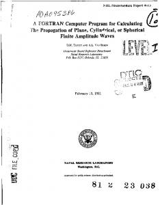
BEARING LOAD COMPUTATION Given the pressure-volume data, several methods can be found in the literature for the bearing load computation of a helical screw compressor 14-61• However these methods either utilize assumptions which simplify the complex rotor profile geometry, which affects the magnitudes of the computed loads, or they use fairly crude methods to calculate axial forces. In the authors' previous paper31 the effects of axial gas forces applied to rotor ends and to helical screw surfaces were taken into account. It is worth mentioning that although the resultant axial force applied to helical screw surfaces is zero in the non-contact region of the rotors 141 , the moments of the axial forces are not zero, as shown in Figure 1. The presence of these moments of the axial forces have a significant influence on bearing radial loads as can be seen from the computed results in the next section (Table 1). The authors' first attempt131 at calculating forces and torques did not take into account inter-rotor contact forces, whereas the method presented here does. It is based on the following simplifications which the authors believe do not result in serious error. The rotor profile considered here and shown in Figure 2, is suitable for male rotor drive. Power is transmitted from the male to the female rotor through the transmission section of the profile (A to K in Figure 2) to . overcome the compression gas-induced resistance torque. Since the compression is carried out in a cavity formed by a
654
pair of rotor lobes, the resistance torque arising from cavity pressure is balanced by the torque due to lobe contact forces in the case of the female rotor which performs the function of an idler in a male rotor drive arrangement. The magnitude of the inter-rotor contact force will in reality vary along the contact line but in the model it is taken to be constant to make a solution achievable. The magnitude and orientation of this force do however vary with time as the rotor angle and cavity pressure vary. From Figure 3 the following relations between the components of the contact forces can be obtained: (1)
I cos(£2i)
(2)
F dfi = F tfi • tan(j32i)
(3)
F '1/i = Ftfi
Substituting Eqn. (2) and (3) into Eqn. (I) leads to
(4) According to the assumptions, the compression gas torque of the cavity equals
(5) from which F 1131 is determined for a male rotor angle of rotation a. Then there exist
(6) and (7) (8) (9) (10) M 1fi = +Fdfi ·r_ --.;
(11)
Since F1131 = Fo,1..,, similar expressions can be derived for the male rotor. For a rotor angle of rotation a, the length of contacting part of the contact line for power transmission has to be decided first, i.e. the start and end points sp and ep. Then the effects of these force components on bearing loads can be determined by numerically integrating from sp to ep. The overall effects of all the cavities are finally obtained by superposing the effects of all individual cavities. In addition to the factors mentioned above, also taken into account are the axial forces applied to shaft ends and the weights of the rotors_ The computer program for bearing load computation is developed to be menu-driven_ After reading rotor profile data, rotor structural data and pressure data, the rotor radial and axial forces and torques together with bearing loads can be computed. The results are saved to disk files and can be displayed on screen and printed or plotted to get hard copy.
655
WORK ING MODE L
ical example relating to an oil injected To demonstrate the capability of this integrated program an numer and running conditions are as follows: refrigeration compressor model is presented. Its main geometrical 204 mm Outer Diameter of rotors: 4/6 Lobe combination: 1.65 ratio: er diamet vs Length 160 mm Centre distance: rpm 3000 speed: g rotatin Male rotor 3 Pressure ratio: radial and axial loads with male rotor angle At full volumetric capacity (slide valve closed) the variation of bearing with time periodically, with a frequency equivalent of rotation is shown in Figure 4. As expected, the bearing loads vary rotor lobes. It can be seen that the axial load on the to the male rotor rotating speed multiplied by the number of male about 3 times of that on female rotor. In contrast, the male rotor is the largest one among all of the components and is rotor, and the loads on the discharge end bearings are radial loads on the female rotor are higher than those on the male always larger than those on the suction end bearings. valve settings are easily obtained as shown With the integrated program, the bearing peak loads at different slide seen that the second highest peak value be It can in Figure 5, with volumetric capacity ranging from 18% to 100%. this value may become larger than that at full appears at a volumetric capacity of about 60%. As mentioned before, capacity under certain circumstances. also gives the contributions to the maximum For the compressor and running conditions studied, the computation surfaces of the screws and the axial forces on the rotor bearing loads of the rotor contacting forces, the axial forces on the direction is from discharge to suction and for radial ends, as shown below (a positive sign means for axial forces that the um values for resultant forces which occur during forces Figure 3 defines sign conventions). The table relates to maxim a compression cycle. Table 1 Contributions of various factors to maximum bearing loads %of F.r %ofF .., %of F,rd % ofF,r. %of Fnm % ofF""' Factors 15.4 43.1 14.0 -21.6 17.7 -29.2 Axial Forces on Screw Surface 100 51.8 -1.31 1.93 2.12. -1.82 Axial forces on Rotor Ends -15.4 5.1 3.87 7.66 -1.78 1.37 Rotor Contact applied to screw surfaces is of significance, It can been seen from this table that the influence of the axial forces contact forces and the axial forces on rotor ends are and must not be ignored in the computation. The effects of the rotor axial loads. relatively small on bearing radial loads, but significant on bearing CONC LUSIO NS
program and a performance simulation program A bearing load program is integrated with a geometrical calculation compressor with various geometrical parameters and which is capable of computing bearing loads of a helical twin screw load program to calculate the contributions of all running conditions. Sophisticated techniques were used in the bearing s and on rotor ends. The capability of such an influencing factors such as rotor contact, axial forces on screw surface essor for a range of slide valve settings. integrated program has been demonstrated by applying it to a compr ACKN OWLE DGEM ENT
n Compressors Ltd., especially in supplying the The authors gratefully acknowledge the support and help of Howde Compressors for permission to publish this paper. data required. The authors also thank the management of Howden
656
REFERENCES 1 2 3
4 5 6
Tang, Y. and Fleming, J.S., Computer Aided Geometrical Analysis of the Geometrical Characteristics of a Helical Screw Compressor, Proceedings of the Chinese Compressor Engineering Conference, Xian, China, July 1993. Tang, Y. and Fleming, J.S., Simulation of the Working Process of an Oil Flooded Helical Screw Compresso r with Liquid Refrigerant Injection, Proceedings of International Compressor Engineering Conference at Purdue, July 1992. You, C.X., Fleming, J.S. and Tang, Y., Computerised Analysis of the Rotor Forces and Torques due to Gas Compression in a Helical Screw Compressor, Proceedings of the Chinese Compressor Engineering Conference, Xian, China, July 1993. Rinder, L., Schraubenverdichter, Wien, Springer-Verlag, 1979. Zhou, Z., Wang, D., Zhu, T. and Mao, J ., Analysis 0/The Applied Forces In Twin-Screw Refrigerant Compresso rs, Proceedings of International Compressor Engineering Conference at Purdue, USA, July 1990. Adams, G. and Soedel, W., Remarks On Oscillating Bearing Loads In Twin Screw Compressors, Proceeding s of International Compressor Engineering Conference at Pmdue, USA, July 1992. Discharge s:ide
No11-contoct
_
_ . 1;>_9rl of eavlfy
Contact pert of cavity
Suction side
Fig. 1 Moments of axial forces applied to screw surfaces
Fig. 2 Power transmission section of the rotor profile concerned
r.,
Fig. 3 Relations between components of rotor contact forces
657
1 .6X1~
r----., ....-"" T-...- -----.. .-......- -.......-...-..... .,.--r-_ _,,.._..
...
·
! 1.2X1~
..
I
.. ,.. ··''
...... -·
~·
......
·
.
.\
•
..,.._.-- -.--,
\
.......·-· '
~
·•.\
. . r
\
l ·........ .•
~
~
~
f
0.8x1~
0.4x1~
Male Rotor Angle of Rotation (dog)
n Fig. 4 Variation of bearing loads with male rotor angle of rotatio
1.5x1a'
·" ·" ."
~
..
"C
.3
/
co 1.0x1~
E
-~
:: 0.5x1a'
25
75
50
Volumetric Capacity (%)
y Fig. 5 Variation of maximum baring loads vs volumetric capacit
658
100