358
IEEE TRANSACTIONS ON AUTOMATION SCIENCE AND ENGINEERING , VOL. 2, NO. 4, OCTOBER 2005
A Generic Deviation-Based Approach for Synthesis of Tolerances Nilmani Pramanik, Utpal Roy, Rachuri Sudarsan, Ram D. Sriram, Senior Member, IEEE, and Kevin W. Lyons
Abstract—In this paper, a generic model for the synthesis of tolerances for manufactured parts is presented. The model uses a method of transforming traditional tolerance specifications (as defined in ASME Y14.5M) to a generalized coordinate system (hereinafter referred to as deviation space). Small displacement torsors (SDTs) have been used for representing the deviations. The tolerance synthesis method is formulated as a constrained nonlinear optimization process. Three different types of constraints have been considered for the optimization process: 1) representation of assemblability; 2) mapping of tolerance specification to deviations; and 3) functional requirements. A new deviation-based cost of manufacturing model has been proposed. A working module of the scheme has been implemented and the process has been elaborated with two examples. The possibility of extension of the model and scope for further generalization have been discussed. Note to Practitioners—This paper presents an optimization method for finding tolerance values for different features of an assembly of manufactured parts. Determination of different types of tolerances and their exact values for critical features of any part has been an ad-hoc process; it has been mostly experience-based till recent time. In this paper, efforts have been made to establish a strong mathematically oriented method for synthesis of tolerances. The procedure attempts to minimize cost of manufacturing while the functionality and assemblability are satisfied. It is a generalized method and could be applied for designing rigid manufacture parts. For practical usage, this method should be integrated with three-dimensional computer-aided design packages as a tolerance synthesis module for integrated tolerance design. Index Terms—Assemblability, cost of manufacturing, deviation space, functional requirements (FRs), tolerance synthesis.
I. INTRODUCTION AND REVIEW OF RELATED WORK
S
YNTHESIS of tolerance for manufactured parts plays a major role in manufacturing. Cost of manufacturing, inspection, assembly and future repairs, etc. all depend on
Manuscript received April 14, 2005. This paper was recommended for publication by Editor M. Wang upon evaluation of the reviewers’ comments. N. Pramanik is with the Department of Industrial Technology, University on Northern Iowa, Cedar Falls, IA 50614 USA (e-mail:
[email protected]). U. Roy is with the Department of Mechanical, Aerospace and Manufacturing Engineering, Syracuse University, Syracuse, NY 13244 USA (e-mail:
[email protected]). R. Sudarsan is with Engineering Management and Systems Engineering Department, George Washington University, Washington, DC 20052 USA, and also with the Design and Process Group, Manufacturing Systems Integration Division, National Institute of Standards and Technology, Gaithersburg, MD 20899 USA (e-mail:
[email protected]). R. D. Sriram is with the Design and Process Group, Manufacturing Systems Integration Division, National Institute of Standards and Technology, Gaithersburg, MD 20899 USA (e-mail:
[email protected]). K. W. Lyons is with the Nanomanufacturing Division of Design, Manufacture and Industrial Innovation, National Science Foundation, Arlington, VA 22230 USA, and also with the Design and Process Group, Manufacturing Systems Integration Division, National Institute of Standards and Technology, Gaithersburg, MD 20899 USA (e-mail:
[email protected]). Digital Object Identifier 10.1109/TASE.2005.853584
these tolerances. Traditionally, designers used size tolerances (plus-minus tolerances) and the tolerances were allocated based on simplified computations and were mostly based on experience and/or rule of standard practice. Subsequently, more stringent requirements for low tolerance and low cost products lead to consideration of geometric tolerances. The synthesis of tolerance for manufactured parts in an assembly essentially means allocation of tolerance values for various features of the parts that are in contact with other features. The objective of tolerance synthesis is to compute suitable tolerance values that would satisfy the overall design goal/objective of the artifact (assembly) and would minimize various costs associated with the product. Both ISO and ASME have their own standards and codes of practice for geometric tolerancing; however, suitable mechanisms to transform these standards into information models are required for computerized synthesis work. There have been several approaches for three-dimensional (3-D) tolerance analysis and synthesis using various computational methods [1]–[5]. In all such methods, geometric connectivity (topology) and the assemblability constraints are generated using some form of vector sum of deviations (variation of surface/feature from it’s nominal shape) along independent paths/loops. The small displacement torsor (SDT) has been used by many researchers [1]–[3] to represent deviations in a very elegant way. In this work, the torsor scheme for representing deviations has been used and a new deviation-based cost of manufacturing formulation has been introduced. A method of mapping traditional tolerance specifications (as per ASME codes) into deviation space has been used [6] to make this approach suitable for synthesis of tolerance in a generic manner. For synthesis and analysis of tolerance, a detailed description of the kinematicfunctions of the assembly is required. Thesekinematic functional specifications may not be directly provided by the customer or by early specifications of the desired product/assembly function. They are slowly evolved with the assembly as the design takes concrete shape and size in the later phases of the conceptual design. Tolerance synthesis and analysis needs an exhaustive functional analysis mechanism to make sure that the identified functional requirements (FRs) between the mating components of the assembly are met and are suitably described using appropriate dimensioning and tolerancing. In this paper, the SDT scheme has been used to represent the variations associated with each feature of a part in the assembly. The proposed tolerance synthesis scheme has been elaborated in the Section II. In Section III details of generation of constraints (assemblability, and FRs) have been presented. The formulation of cost functions and the optimization process has been given in Section IV. Implementation related issues are briefly discussed in Section V. In Section VI results of tolerance synthesis from two examples
1545-5955/$20.00 © 2005 IEEE
PRAMANIK et al.: GENERIC DEVIATION-BASED APPROACH
are presented. Scope of future work in this direction has been discussed in the conclusion. II. TOLERANCE SYNTHESIS SCHEME The following are the steps for the tolerance synthesis. 1) For each component of an artifact, develop the kinematic degrees of freedom (DOF) requirement between the mating features and decide the nature of deviation of the feature from the nominal feature dimensions. 2) For each pair of connected features, establish the deviation parameters of a gap element between the features that can be used to prescribe functional and other kinematic requirements between the features. 3) Generate assemblability constraints by considering all chain of connected parts as a kinematic link (either closed loop or open paths between two datum features) and aggregate the torsors along each path with reference to a global frame of reference. Each loop/path would then generate six equations binding the deviation parameters associated with the related features in the loop. These constraints define a restricted zone in the entire deviation space. In order to satisfy these constraints, our search for a set of suitable deviation parameters has to be confined within this zone. 4) Generate FRs as constraints based on the specified functions/objectives to be fulfilled by the artifact. This will restrict the range of values of the deviations within which a component must remain to fulfill specific FRs. Use of domain dependent knowledge base would be suitable for generating FRs for specific applications. 5) Generate manufacturing/ production cost models for each component (based on suitable knowledge base for manufacturing/ production cost) for different machining operations and formulate a minimization scheme by considering the sum of costs for machining all the parts as the cost function subject to the constraints defined in steps 3 and 4 above. 6) Use standard mathematical tools to solve the minimization problem to find the optimal deviation parameters for each feature. 7) Convert the optimal deviation parameters into appropriate tolerances through tolerance mapping scheme. III. GENERATION OF CONSTRAINTS There are three types of constraints associated with the tolerance synthesis process. Two of them are: constraints of FRs (performance), and constraints of kinematic mating requirements (assemblability). The third category of constraints is generated from many-to-many mappings between tolerance specifications (as per ASME Y14.5 and/or ISO) and the deviation parameters. A. Constraints of Functional Requirements FRs are design requirements specified explicitly as well as implicitly by the user and designers to meet certain desired performance from the artifact. FR, in general, would translate into sets of nonlinear constraints (i.e., functional relationship between the deviation parameters). FR can be thought of in two different ways: as a goal satisfaction to minimize a penalty cost for deviating from the design
359
specification or as a set of constraints in the deviation space. In order to treat FR on a generic basis, a process is required to transform the FR into corresponding set of constraints in terms of the deviation parameters. The FR mainly translate into in, . However, there could equalities of the form: be equality type constraints as well. If some FR are specified as conditions between two mating features, same could be formulated using the deviation parameters of the gap between the two features. The gap between two mating features is defined as a gap element and a torsor (gap torsor) is used to represent the parameters of a gap element (vide CONSTRAINTS OF ASSEMBLABILITY in the following section). For example, an allowable linear gap of 0.01 in the normal direction between two mating , planar features could be represented as where is the displacement component in local coordinate (which is normal to the nominal plane of the features) of the gap torsor between the two mating features and . It is possible that some FRs are specified as constraints between nonmating features and in those cases only the gap torsor would not be sufficient to represent the FR. This category of constraints would go into the general category of constraints defined above. B. Constraints of Assemblability The constraints arising from the kinematic requirements between the mating surfaces to meet the requirement of transmission and/or blocking of the desired flow of energy, force, torque, etc., through the mating area could be treated as kinematic constraints. Let us take an example to elaborate the steps described above for the tolerance synthesis process. The example ( a spur gear assembly) has been taken from a design evolution solution [7] where the design evolution process has been illustrated by taking an example of designing a device for transmitting torque with changing rotational speed.. The gear-subassembly consists of three parts: a spur gear, a shaft with a keyhole, and a key. The geometric models of these three parts, including their feature-level mating relationships have been shown in Figs. 1 and 2. After the torsors for each of the mating features have been defined, the assembly graph of the artifact (Fig. 3.) is considered and all independent closed loops and paths are enumerated for generating equations that represent various possible geometric configurations for the artifact. torsor, feature, Thus, for example, with the notation part , and gap between two mating features, a typical closed loop from Fig. 3, would be represented by
The aggregation of the torsors (transforming them into global reference, as needed) should then be equated to a null torsor. This will give six equations connecting the components of the torsors associated with the loop. The gap between the mating features is used as constraints to satisfy specific design FRs as well as kinematic requirements. For computations in each loop, the local variations are to be converted to a global coordinate system by transformation of
360
IEEE TRANSACTIONS ON AUTOMATION SCIENCE AND ENGINEERING , VOL. 2, NO. 4, OCTOBER 2005
Fig. 4. Loops/paths in an assembly.
is the starting as required to traverse a loop/path. Here, point (from_part, from_feature), is the gap torsor between two are intermediate connections [(to_feafeatures, ture, part, from_feature), gap] along the path to the next part, is the end point (to_feature, to_part). Symbolically, and this can be represented as shown in Fig. 4. In case of a closed loop, the last part would be the first part. For open loops, both the starting and the final parts should be terminals (datums). In case of closed loops, the summation of the torsors would be a null (0) torsor, whereas for an open path, the summation could be a nonnull torsor (designated as ) that has to be established from known functional specifications between the two terminals. Notation: torsor with index , , for parts, features Part , Feature of part and gaps respectively, , deviation torsor of the feature , defined at a suitable gap torsor defined at a mating point on the feature and between two features. With the above notation, and a sign convention for adding the torsors in a loop (positive when going out from a feature and negative when entering a feature), the desired equations for each loop could be written as
Fig. 1. Spur gear subassembly.
Fig. 2. Mating features of the gear subassembly.
(2) Summing over the entire loop, and using the torsor transformation rules (Appendix A), (2) can be converted to the following compact form: Fig. 3. Assembly graph of the gear subassembly.
(3)
the corresponding torsors in the local frame. In the present example, the center of the inner shaft could be taken as the reference origin and all the components of the deviation torsors could be expressed in terms of vectors emanating from that point. While traversing these loops, the gap between the two mating features plays a vital role in deciding the type of interface between the two mating features. The gap torsor is required to model the functional specifications for the given mating conditions. After all the loops have been considered and corresponding equations have been formed, we get a system of equations that define the possible geometric variations of the artifact configuration. The torsors in each loop/path are summed with appropriate transformations (Appendix A) and each of the six components of the torsor is equated to zero for a loop (or equated to a pre-assigned quantity for open paths) to get six equations connecting all the deviation parameters in the loop/path. Without any loss of generality, we can assume that each loop/path could be enumerated as a linked list defined by
(4)
(1) part , where tures. Items within
feature, and gap between mating feacould be repeated zero or more times
is the local-to-global transformation matrix for feawhere and ture defined in Appendix A. are the two vectors formed from the linear & rotational components respectively of the deviation torsor of the feature . Equations (3) and (4) could be written as a single ma, where and . trix equation: C. Mapping Tolerance to Deviation Parameters Since deviation parameters have been used to represent the geometric variations, a mechanism is required to express standard tolerances specifications as per ASME Y14.5 in terms of these deviation parameters so that any solution in deviation space could be mapped in to standard tolerancing schemes like ASME Y14.5M and vice versa. It has been shown in [6] that such mappings exist. The category of relationships that arise from these mappings are of the generic form where is the deviation parameter, is an index, and is the tolerance parameter. Exact and are dependent on forms of the functions the nature of the feature/surface and the tolerance specification.
PRAMANIK et al.: GENERIC DEVIATION-BASED APPROACH
361
lifespan has been treated by constructing a functional performance index generated from the effect of tolerance. However, the work is applicable to very specific domains and cannot be used universally. In the present scheme these costs have not been considered, however, provisions have been kept for a generalized cost of manufacturing model so that the designer can easily introduce/modify the cost functions associated with each part/feature in the artifact library [7]. Fig. 5.
A. Cost of Manufacturing
Planar (rectangular) feature with size tolerance.
Shrinivasan [8] has shown that there are seven possible symmetry classes that are encountered in engineering applications: spherical, cylindrical, planar, helical, revolute, prismatic and complex. Each of them has it’s own rotational/translational independence (invariants). In this case, the DOF corresponding to the invariants of these features are removed and the remaining DOF are combined with that of the mating features. For example, for a cylindrical feature, axial movement and axial rotation are two invariants and these two can be eliminated leaving us with four parameters. For a planar surface the above mapping becomes a set of linear constraints. The linear nature of the equations, however, does not exist when we consider nonplanar features. Deviation to tolerance mapping has been discussed in detail in [6]. In this paper, we will need relations for planar and cylindrical features. Relations for the planar case is shown below. In upper limit of size this example, the notation used are tolerance, lower limit of size tolerance, positional tolerance, perpendicularity tolerance, and six components of the deviation torsor Planar Feature: For the planar feature shown in Fig. 5, the deviation parameters are: . The size tolerance is taken with respect to a datum and the planar face is rectangular with sides and (Fig. 5) Four constraints are established by considering the deviation of the four extreme points (corners) of the plane which are nominally at , , and
and
(5)
IV. FORMULATION OF COST FUNCTIONS The cost function to be minimized can have several components, including: cost of manufacturing, cost of assembling, cost of inspection, cost related to product lifespan, cost to meet FRs, cost to meet assemblability, etc, In this paper, only the cost of manufacturing has been considered and the cost of manufacturing has been treated as a deviation-dependent function. Although for completeness further work would be needed to formulate other cost factors (apart from cost of manufacturing) mentioned above, the treatment of the cost functions for the optimization has been kept generic so that new cost functions could be added easily. Some authors have done context-specific work on the above costs and, for example, in [9] the effect of tolerance on cost related to product
Apart from the tolerance specification, costs associated with manufacturing a part are dependent on material, dimensions, geometric shape, sequence of manufacturing operations, and the process capabilities. Many researchers have analyzed various issues associated with the cost of manufacturing in relation to tolerances. Essentially all cost of manufacturing formulations are monotonically decreasing functions of a single tolerance parameter. Effects of various functional forms like inverse power law, exponential decay, etc., and the effect of process capabilities have been studied by many researchers [9]. Since, in general, more than one operation is required to transform the raw blank into the final finished part, the cost of manufacturing is a function of the process sequence and how much accuracy is achieved in each stages of operation. The cost will also be affected by the setup error in each machining process. The total cost of production thus becomes a sum of the costs associated with each process [10]. While none of these methods mentioned above could claim to be universal, there are several limitations with the one-parameter (single tolerance) cost of manufacturing formulation. In reality, a manufactured surface would rarely have a single tolerance value. Apart from a size tolerance, there could be geometric tolerances (form., positional, and orientation tolerances, etc) and it would be difficult to formulate a single parameter representing all these tolerances that could effectively be used for representing the cost of manufacturing. In order to circumvent the above problem, a new deviation-based formulation for cost of manufacturing is proposed here. B. Deviation-Based Cost of Manufacturing For modeling the cost of manufacturing, some form of generic function of the deviation parameters could be used and the mapping between the deviation parameters and the tolerance parameters would be used to link the cost function to the tolerance specification. Thus, the cost function defined as a function of some tolerance parameter , would become a function of the six deviation parameters . There could be various forms/structures for these functions depending on specific surfaces and manufacturing processes and experimental results would be needed to establish typical functions for domain-specific application. In this work the cost of manufacturing a part is considered as an explicit product of six functions of the six deviation parameters in the form (6) is where the deviation parameters characteristic of the feature. Depending on the nature/type of a feature, some of the functions will be constants (invariants) and could be eliminated, for
362
IEEE TRANSACTIONS ON AUTOMATION SCIENCE AND ENGINEERING , VOL. 2, NO. 4, OCTOBER 2005
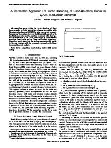
example, for some , . This will correspond to the deviation parameters that are invariants of the feature. As for an example, for a planar surface there are only three that independent parameters given by affect the deviation of the surface from its nominal shape. The cost function can then be represented as (7) Also, in this case, the form of the two functions for rotational deviations along and -axes could be of same form, namely, . For example, for a rectangular planar section with cross ), the mappings from (5) could be written as section ( Fig. 6.
Example of a deviation-based cost function.
(8) (9) are the lower and upper values of the tolerwhere ance parameter for the planar surface. Above relationship could . The be considered as restrictions on the parameters cost function (7) will be restricted accordingly. To illustrate the cost function, a generic function of the form: is considered, where is a small constant used to avoid singularity at origin , is the deviation parameter and & are cost constants. Thus, the cost function becomes
For a visual representation of this function as a surface in 3-D, , and using , removing the term, assuming , the constraints become: , , , and and the cost function is
In the plane, this would look like a tent bounded by four vertical planes defined by the four limits from the tolerance specification. (Fig. 6) C. Summary of the Optimization Process Based on the models described above, the optimization process could be summarized as minimize: cost of production (10) subject to Functional constraints Assemblability constraints And deviation to tolerance mapping constraints
(11) (12) (13)
where is the deviation parameter of the th feature of part in the assembly, is the matrix formed as described in Section III, , , , is the
number of constraints. is function of deviation parameter function of known tolerance parameters. and The “fmincon” function of Matlab has been used to solve the constrained nonlinear optimization problem given by (10)–(13). Further details of the optimization process are given in the tolerance synthesis example after the implementation section.
V. IMPLEMENTATION OF MODEL The object-oriented approach has been used to represent entities (classes) in the tolerance synthesis scheme and the major classes are: artifact, assembly tree, tolerance, function, behavior, torsor, and cost of manufacturing. The class structures have been developed using UML and the system has been implementation in MS VB 6.0. A. Basic Steps of Operation The program operates in two phases. In the first phase, the designer builds the model using standard artifact elements. All geometric entities for each part and feature like nodal coordinates, definition of features, surfaces, datums, known deviations, specified constraints, etc. are supplied by the designer. After a model has been established, the module generates the loops and paths using an exhaustive search. Assemblability constraints are then generated and stored in a sparse matrix format. Constraints for FRs are generated based on the requirements specified by he designer. The default cost of manufacturing function is generated based on specified forms (for example, these two forms and have been tried). However, any suitable continuous function could be specified by the designer. Apart from the above, several other specifications are required to make the model stable and solvable. These include: establishing datum reference frames, defining terminal parts with known/specified deviations and specifying possible upper and lower limit for the deviation parameters. Based on the constraints and cost functions generated by the module, the optimization is carried out in Matlab and a successful execution produces a set of optimum deviation parameters. The solution is then transferred to the main module for further study including viewing the distorted shapes, and applying the deviation to tolerance mappings for arriving at suitable tolerance specifications for each feature.
PRAMANIK et al.: GENERIC DEVIATION-BASED APPROACH
363
Fig. 9. Example model – Part #1. Fig. 7. Example assembly – Nominal shape/size.
Fig. 8.
Planetary gearbox.
VI. EXAMPLE OF TOLERANCE SYNTHESIS In this section, the proposed method is illustrated by taking two examples. The first example is a simple 3-D planar assembly with three rectangular blocks (Fig. 7) and the second one is simplified planetary gearbox (Fig. 8). For preparing the input, each point of interest on a feature or part in the assembly is identified with a node (numbered 1 to ). The nodal coordinates are given in a global coordinate system. Each part is given a serial number. Based on the input data, the system generates all local coordinate systems (LCS) at the center of each feature with outward normal to the surface as local axis (Fig. 9 shows the nodes and LCS of part 1). The specified connectivity is used to draw the assembly graph (Fig. 10) and all independent loops (paths) are then generated. For this example, there are six (6) independent loops Path Path Path Path Path Path Each path consists of a sequence of four numbers in parenthesis to denote fromPart fromFeature toPart toFeature , respectively. A typical link (corresponding to path-002) is shown in Fig. 10 using dotted arrows. A. Parameters of the Example In this example, there are 17 active nodes requiring 102 deviation parameters and there are 36 equality constraints corre-
Fig. 10.
Assembly graph for the example problem.
Fig. 11.
Example model—Distorted shape.
sponding to the six (6) loops. The cost function for this problem and the Matlab version is taken in the form: of the cost function has been shown in Appendix B. Based on these formulations, the optimization problem has been solved in Matlab and the results are used for visual display of the distorted shape (Fig. 11) and tolerance computations. Table I shows the optimal deviation values obtained from the Matlab run. Tolerance ranges for the features are computed using the mapping relations (5). For example, for feature 1 of part 1, deviations at node 2 is: , , . For this planar feature and . Using (5), the four relations become: , , , and . Taking the extreme points, the size tolerance for this feature is found as ( , ).
364
IEEE TRANSACTIONS ON AUTOMATION SCIENCE AND ENGINEERING , VOL. 2, NO. 4, OCTOBER 2005
TABLE I OPTIMAL DEVIATION PARAMETERS
Fig. 12.
Example model—Computed tolerances.
Table II shows the final tolerance values and Fig. 12 shows corresponding tolerance specification. The second example is a simplified model of a planetary gearbox (Fig. 8). It’s relatively complex, realistic and has both planar and cylindrical features. An exploded schematic view of the gearbox modeled for the synthesis is shown in Fig. 13. The results of this example are taken from [11]. The synthesis procedure is identical to the first example, however, the cost functions are different and the deviation to tolerance mapping is carried out using corresponding mapping relations for planar and cylindrical feature. Parameters of this example are: 306 deviation parameters and 672 linear equality constraints. Matlab version of the cost function for this example has been shown in Appendix C. A typical Matlab minimization run for this example on a 1 GHz Dell OptiPlex GX110 system with 256 MB RAM took about 25 min. Tolerance synthesis results for the planar features are shown in Table III and those for the cylindrical features are and values corregiven in Table IV. In Table IV, the spond to those shown in (6) and instead of a plus–minus tolerance, they represent tolerance zones. B. Discussion on Implementation and Resuts While implementing the method, several points were observed which are discussed below. To enumerate all independent loops/paths in the assembly graph, an exhaustive search were used and a strategy to dynam-
Fig. 13. Gearbox modeled as a 5-part system. Node numbers identify point of interest on the feature for representing SDT.
ically eliminate duplicate paths was employed. A simple string search strategy has been used to detect inner loops. The -matrix generated for the assemblability constraint is sparse in nature and a tree-structured list is used to store only the nonzero terms. This sparse matrix representation would be useful for solution of large systems with complex configurations. Since one deviation torsor is required for each feature and one gap torsor is required between two mating features, number of variables increase linearly with number of features. However, the number of assemblability constraints (number of rows of the -matrix) depends on the number of independent paths, which, in turn, depend on the complexity of the mating configuration. Thus, depending on the problem configuration, number of constraints could be more than the number of variables which could lead to over-constrained systems whereas for simpler configurations, number of constraints could be less than number of variables which could make the system under-constrained. VII. COMPUTATIONAL ISSUES AND FURTHER ENHANCEMENTS OF OPTIMIZATION PROCESS The results from the example problems given above were based on successful optimization runs with assemblability constraints derived by exhaustive enumeration of all loops in the
PRAMANIK et al.: GENERIC DEVIATION-BASED APPROACH
365
TABLE II DEVIATION TO TOLERANCE MAPPING
TABLE III TOLERANCE VALUES FOR CIRCULAR PLANAR FEATURES
Fig. 14.
Typical convergence of an optimization run.
Fig. 15.
Optimal cost versus bound on deviations.
TABLE IV TOLERANCE ZONES/VALUES FOR CYLINDRICAL FEATURES
assembly. While the optimization formulation gives converging solutions, it is observed that the computational overhead (processing time and memory requirements) increases rapidly as we consider large assemblies with many components. This is due to the fact that number of loops (and corresponding number of assemblability constraints) increases very rapidly for complex assembly graphs. This makes the optimization model rather restrictive to small to medium sized problems. In order to improve the efficiency of the algorithm, we needed a mechanism to eliminate nonactive and dependent constraints. Subsequent to our work as detailed above, Wang [12] studied the problem from graph theoretical aspects and successfully implemented a spanning tree based procedure for enumerating the independent loops in an assembly graph. We have applied
this technique on the example gearbox problem by taking only the independent loops for generating the assemblability constraints. This method reduces the number of constraints from 672 to 60. We have subsequently carried out several successful optimization runs with various bounds on the deviations parameters and different convergence criteria and the optimization runs (fmincon, Matlab 7) converge rapidly. Appendixes C and D show the cost function and the Matlab m-file for the optimization respectively. Fig. 14 shows the typical convergence trend of an optimization run. In this example (gearbox problem), a series of comparative runs were taken to compare results with the earlier optimization with all loops. In this case a reduction of computation time by an order of about 25 has been observed. In order to establish the trend in optimal cost and execution times, several optimizations runs were carried out using the bounds on the deviation parameters as the independent vector. Fig. 15 shows the trend in the optimal cost values. The optimal
366
IEEE TRANSACTIONS ON AUTOMATION SCIENCE AND ENGINEERING , VOL. 2, NO. 4, OCTOBER 2005
This could be written in compact notation as where is the 6 6 transformation matrix given by
(14)
Fig. 16.
Execution time versus bound on deviations.
is the vector from point to in global coordinate system . After the above transformation, the components of torsor are still in the local coordinate system . Let the local coordinate system be defined by the three , and unit vectors in the global coordinate system, in other words, the local to global coordinate transformation could be represented by the matrix given by (15)
Fig. 17. Transformation of torsors, local to global.
cost values follow a definite inverse law with increase in deviation (tolerance bounds) as should be expected. The execution times, however, does not follow a definite pattern (Fig. 16) as could be expected for a highly nonlinear optimization process; however, there is an overall linear trend in reduction of execution time with increase in the bounds. Above results (improvement in computational efficacy) could make the proposed method suitable for integration with computer-aided design (CAD) packages for real-time tolerance synthesis. Further study is needed on models of different levels of complexity to establish more reliable execution timings. We plan to report further details of the integration with results of case studies in our future publications.
The components of could then be converted to the global system by the applying the matrix to the small rotations and the linear movements (16) (17) where , , , subscripts and refer to global and local coordinate systems respectively and is the vector cross product. Combining the two transformations, we can write the final result as or (18) APPENDIX B COST FUNCTION FOR EXAMPLE PROBLEM
A. Conclusion and Future Work In this paper, a generic model for the synthesis of tolerances has been presented and a working module has been implemented that could automate the process of tolerance synthesis. In this approach, a new deviation-based model for cost of manufacturing has been formulated. APPENDIX A TRANSFORMATION OF TORSORS is defined at a point (Fig. 17) in the local coAn SDT with six components ( , , , , ordinate system , ), where denotes rotational and denotes linear components of movements. (where denotes local This torsor transforms to coordinate system) in the same local coordinate system shifted as to a new point
costfun Function % deviation dependent cost of manufacturing formulation % generated from tnp3. Nilmani Pramanik/Jun 25, 2002 global ; ; ; ; ; ; ; ; ; ; ; ; if
end
PRAMANIK et al.: GENERIC DEVIATION-BASED APPROACH
APPENDIX C COST FUNCTION FOR GEARBOX EXAMPLE costfun Function % deviation dependent cost of manufacturing formulation % generated from tnp3. Dec 10, 2004 21:25:34 global
if end
367
368
IEEE TRANSACTIONS ON AUTOMATION SCIENCE AND ENGINEERING , VOL. 2, NO. 4, OCTOBER 2005
ACKNOWLEDGMENT No approval or endorsement of any commercial product by the National Institute of Standards and Technology is implied. Certain commercial equipments, instruments, or materials are identified in this work in order to facilitate a better understanding. Such an identification does not imply endorsement or recommendation by the National Institute of Standards and Technology, nor does it imply that the materials or equipment identified are necessarily the best available for the purpose. REFERENCES [1] E. Ballot and P. Bourdet, “A mathematical model of geometric errors in the case of specification and 3-D control of mechanical parts,” in Advanced Mathematical and Computational Tools in Metrology IV. Singapore: World Scientific Publishing, 2000. [2] , “A computation method for the consequences of geometric errors in mechanisms,” in Geometric Design Tolerancing: Theories, Standards and Applications, H. A. Elmaraghy, Ed. London, U.K.: Chapman & Hall, 1998, pp. 197–207. [3] A. Clement, A. Riviere, P. Serre, and C. Valade, “The TTRSs: 13 constraints for dimensioning and tolerancing,” in Geometric Design Tolerancing: Theories, Standards and Applications, H. A. Elmaraghy, Ed. London, U.K.: Chapman & Hall, 1998, pp. 122–131. [4] K. Chase, S. Magleby, and J. Gao, “Tolerance analysis of two- and three-dimensional mechanical assemblies with small kinematic adjustments,” in Advanced Tolerancing Techniques, H.-C. Zhang, Ed. New York: Wiley, 1997, pp. 367–377. [5] K. Chase, J. Gao, S. Magleby, and C. D. Sorensen, “Including geometric feature variations in tolerance analysis of mechanical assemblies,” in IIE Trans., 1996, vol. 28, pp. 795–807. [6] H. Wang, N. Pramanik, U. Roy, R. Sudarsan, R. D. Sriram, and K. W. Lyons, “A scheme for transformation of tolerance specification to generalized deviation space for use in tolerance synthesis and analysis,” in Proc. ASME Design Engineering Conf., Montreal, QC, Canada, Sep. 2002, DETC2002/DAC-34 146. [7] U. Roy, N. Pramanik, R. Sudarsan, R. D. Sriram, and K. W. Lyons, “Function-to-form mapping: model, representation and applications in design synthesis,” Comp.-Aided Des., vol. 33, pp. 699–719, 2001. [8] V. Srinivasan, “A geometric product specification language based on a classification of symmetry groups,” J. Comput.-Aided Des., vol. 31, pp. 659–668, 1999. [9] Z. Dong, “Tolerance synthesis by manufacturing cost modeling and design optimization,” in Advanced Tolerancing Techniques, H.-C. Zhang, Ed. New York: Wiley, 1997, pp. 233–260. [10] U. Roy and Y.-C. Fang, “Optimal tolerance re-allocation for the generative process sequence,” IIE Trans., vol. 29, pp. 37–44, 1997. [11] N. Pramanik, U. Roy, R. Sudarsan, R. D. Sriram, and K. W. Lyons, “Syntheis of geometric tolerances of a gearbox using a deviation-based tolerance synthesis scheme,” in Proc. ASME 2003 Design Engineering Technical Conf., Chicago, IL, Sep. 2–6, 2003, DETC2003/CIE-48 192. [12] H. Wang, “Graph-Based mechanical product family modeling and functional tolerancing for mass customization,” Ph.D. dissertation, Dep. Mech. Eng., Syracuse Univ., Syracuse, NY, 2004.
Nilmani Pramanik received the B.S. degree in mechanical engineering from Jadavpur University, Kolkata, India, the M.S. degree from Birla Institute of Technological Sciences, Pilani, India, and the Ph.D. degree in mechanical engineering, from Syracuse University, Syracuse, NY. He is an Assistant Professor of Manufacturing Technology in the Department of Industrial Technology, University of Northern Iowa, Cedar Falls, IA. He holds more than 15 years of industrial experience in engineering design, analysis, and development of engineering and enterprise resource planning (ERP) software. His areas of interest are computer-aided design and modeling systems, geometric tolerancing, mathematical modeling, object-oriented programming, expert systems, and artificial intelligence applications.
Utpal Roy is a Professor in the Mechanical, Aerospace, and Manufacturing Engineering Department, Syracuse University, Syracuse, NY. His current research interests include geometric tolerance analysis and synthesis, knowledge-based computer-aided engineering, and product development.
Rachuri Sudarsan received the M.S. and Ph.D. degrees from the Indian Institute of Science, Bangalore, India. He is a Research Professor in the Department of Engineering Management, George Washington University, Washington, DC. He is also a Guest Researcher with the Design and Process Group, Manufacturing Systems Integration Division, National Institute of Science and Technology (NIST), Gaithersburg, MD. Presently, his work at NIST includes development of information models for product lifecycle management, assembly models and system level tolerancing, and standards development. He coordinates research projects with industry and academia. He closely works with various standard bodies including ISO TC 184/SC4. His areas of interest include scientific computing, mathematical modeling, product lifecycle management, ontology modeling, system level tolerancing, quality, object oriented modeling, and knowledge engineering. Prof. Sudarsan is a member of ASME Y14.5.1 and Advisory Group Member for ISO/TC 213/AG12, Mathematical Support for GPS. He is the Regional Editor (North America) for the International Journal of Product Development, and Associate Editor for the International Journal of Product Lifecycle Management. Ram D. Sriram (SM’00) received the B.S. degree from the Indian Institute of Technology, Madras, India, and the M.S. and Ph.D. degrees from Carnegie Mellon University, Pittsburgh, PA. He currently leads the Design and Process Group in the Manufacturing Systems Integration Division, National Institute of Standards and Technology, where he conducts research on standards for interoperability of computer-aided design systems and on healthcare informatics. Prior to this, he was on the engineering faculty (1986–1994) at the Massachusetts Institute of Technology (MIT), Cambridge, MA, and was instrumental in setting up the Intelligent Engineering Systems Laboratory. At MIT, he initiated the MIT-DICE project, which was one of the pioneering projects in collaborative engineering. He has coauthored or authored more than 175 papers, books, and reports in computer-aided engineering, including 13 books. Prof. Sriram was a Founding Co-editor of the International Journal for AI in Engineering. In 1989, he was awarded a Presidential Young Investigators Award from the National Science Foundation. Kevin W. Lyons received the B.S. degree in mechanical engineering from the University of Florida, Gainesville, and the M.S. degree in mechanical engineering from the University of Maryland, College Park. From 1977 to 1992, he worked in industry in various staff and supervisory positions dealing in engineering marketing, product design and analysis, factory automation, and quality engineering. From 1996 to 1999, he served as Program Manager with the Defense Advanced Research Projects Agency (DARPA), where he was responsible for the conceptualization, development, and execution of advanced research and development programs in design and manufacturing. He is currently the Program Director of the Nanomanufacturing Program at the National Science Foundation (NSF), Arlington, VA. The program emphasizes scale-up of nanotechnology for high rate production, reliability, robustness, yield, efficiency, and cost issues for manufacturing products and services. In addition to his program responsibilities, he oversees two existing Nanomanufacturing Centers and a third Center that will be selected in Fall 2005. Prior to his NSF assignment, he was a Program Manager with the Manufacturing Engineering Laboratory at the National Institute of Standards and Technology, Gaithersburg, MD. His responsibilities included research in nanomanufacturing, assembly, virtual assembly, and rapid prototyping.