2016 IEEE International Conference on Automation Science and Engineering (CASE) Fort Worth, TX, USA, August 21-24, 2016
A Generic Optimization-based Framework for Reactive Collision Avoidance in Bipedal Locomotion Chengxu Zhou*† , Cheng Fang* , Xin Wang*‡ , Zhibin Li*§ , Nikos Tsagarakis* Abstract— In this work we present a novel and generic framework for reactive collision avoidance in bipedal locomotion, which is formulated as an optimization problem considering the constraints of collision avoidance as well as others (e.g. joint limits) to simultaneously satisfy both Cartesian and joint space objectives. To realize the reactive behaviors, several task space motions, such as the translational motion of the swing foot and the vertical position of the support foot, could be relaxed in presence of obstacles. Therefore, the swing foot trajectory is modulated with respect to the references in realtime for preventing future collisions between the legs, or legs and obstacles in the environment. External obstacle negotiation in the proposed framework can also be addressed generically by treating the obstacle as an extended segment of the support foot. The allowable deviation of the relaxed degrees of freedom from their references could be further utilized to modify the foot placement to regenerate a reactive walking pattern. The validation and the performance of the proposed method are fully evaluated and demonstrated in physics based simulations of the compliant humanoid robot COMAN.
I. I NTRODUCTION The real world contains uncertainties and obstacles that are dynamically changing compared to a static lab space where humanoid robots can perfectly perform most locomotion and balancing tasks within a well structured environment. The use of simplified models (e.g. Linear Inverted Pendulum Model [1]) for dynamic walking pattern generation is not always adequate to execute effective and stable locomotion in real world because these simplified models only consider the Center of Mass (CoM) dynamics, and neglect the robot’s whole body kinematics constraints. Moreover, these models are based on several assumptions, such as point mass, constant CoM height, point foot etc., which are not always valid when humanoid robots need to perform more complicated locomotion tasks in unstructured environments and terrains than simply walking on a flat ground. In these cases, selfcollision might occur between two legs of the humanoid or between the legs and the surrounding environment. In this situation, safe interaction of the humanoid and the environment or even people could not be ensured. The skill of avoiding both internal and external collisions during locomotion is thus of vital importance to make humanoids * Department of Advanced Robotics, Istituto Italiano di Tecnologia, via Morego, 30, 16163 Genova, Italy. Tel.: +39-010-71781407. Fax: +39-010-71781232.
[email protected] † Corresponding author.
[email protected] ‡ Shenzhen Academy of Aerospace Technology, 518057, Shenzhen, China. § School of Informatics, University of Edinburgh, 10 Crichton St, Edinburgh EH8 9AB, United Kingdom.
978-1-5090-2409-4/16/$31.00 ©2016 IEEE
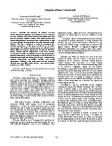
collision
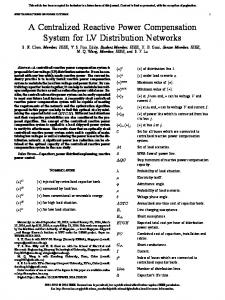
Fig. 1. Obstacle negotiations without (left) and with (right) considering collision avoidance constraints.
more effective for performing safe and stable locomotion in shared human workspace. Collisions between the robot’s segments, specially the legs, could be inevitable when defective gait parameters have been commanded, such as cross-legged walking, wide step turning etc. Self-collision avoidance is widely realized in robotic manipulators [2] like the arms of a humanoid robot due to their redundant properties. Sugiura et al. [3] proposed a collision avoidance method which uses virtual forces and task intervals to avoid upper-limb self-collisions. HRP-2 could avoid collision and self-collision on the basis of a new proximity distance computation method which ensures continuous gradient in stack of tasks structure [4]. Although self-collisions in the upper body could be prevented by suspending the robot with emergency stop, it is unlikely that the self-collisions of lower-body with dynamic constraints could be avoided in this way as well, since both the humanoid itself or the humans interacting with it would be in danger due to the loss of dynamic stability. Realizing self-collision avoidance between legs and other segments during locomotion is therefore required. Towards this direction Kuffner et al. [5] proposed a framework that checks the self-collisions of future three steps before execution. Similarly Kanehiro et al. [6] realized self-collision avoidance during walking on HRP-2 by integrating geometric constraints into leg motion generation, however, the robot’s ability in external obstacle negotiation was not discussed. When encountering an obstacle, the robot could either replan a path to bypass [7]–[9], or utilize its kinematics capabilities to step over [10]–[12]. Guan et al. [10] focused on overstepping obstacles in a quasi-static manner. In contrast, Stasse et al. [11] achieved faster overstepping motion considering the dynamic stability on HRP-2. Zhou et al. [12]
1026
utilized the robot’s pelvis rotation and swing foot abduction for dynamically overstepping large obstacles. However, these methods try to plan desirable motions in advance to avoid collisions with the obstacle, but do not further consider the potential self-collisions or other constraints during motion such as singularities, joint limits etc. This deficiency is a barrier to the potential maximum mobility that can be achieved by a humanoid robot. Furthermore, the robot’s kinematic configuration and the external obstacle information in a dynamic and unstructured environment at a certain future moment would be usually very difficult or may not even possible to be acquired beforehand. Therefore, reactively updating the original planned feet trajectories at high control frequency becomes very necessary and crucial to guarantee the avoidance of self-collisions or obstacles in a dynamically changing environment. Recently, Hildebrandt et al. [13] integrated computer vision, footstep planner and reactive collision avoidance for the humanoid Lola to dynamically react to external obstacles with the ability of self-collision avoidance. In [13], the obstacle and the self-collision avoidance are realized in different ways. Specifically, the obstacle avoidance is achieved firstly by modifying the swing foot reference trajectory based on a local optimization technique, which projects a cost function into the task space of the swing foot. Subsequently, by exploiting the kinematic redundancy of legs, the selfcollision avoidance is realized using an analytical local selfmotion (i.e. null space) optimization scheme, which implies that the robot leg should have enough redundancy to achieve self-collision avoidance. Moreover, with respect to the swing foot trajectory tracking task, the self-collision avoidance as a secondary task has difficulty to be fully accomplished if some erroneous swing foot trajectories are commanded. In order to improve humanoids’ performance in collision avoidance during biped locomotion, a succinct, reliable and unified optimization-based framework is proposed in this paper. The main contributions of the work are: 1) The collision avoidance is formulated as an optimization problem which considers both the obstacle collision and self-collision avoidance as hard constraints in a unified way. Therefore, the collision avoidance task actually has the top priority among all the tasks since it must be respected in any cases. 2) The Cartesian and joint space tasks are realized simultaneously by minimizing the errors of these tasks in the optimization. 3) Minimizing the errors of Cartesian space tasks instead of strictly tracking these tasks actively creates solution space for optimization to formulate collision avoidance. Hence, the proposed framework is applicable to the implementations on the robots with or without redundancy in legs. Fig. 1 shows an example of the robot’s locomotion adaptation behavior while encountering an obstacle without (left) and with (right) the proposed strategy. The presentation of the work is organized as follows. Section II formulates the optimization problem for reactive collision avoidance, and describes the objectives and constraints as well as the landing position modification. In Section III, several simulations are studied on the compliant
humanoid robot COMAN to validate the proposed method in the scenarios of cross-legged walking and external obstacle avoidance. We summarize and conclude our study in Section IV. II. C ONTROL P RINCIPLE A. Formulation of Optimization Problem Generally, gait patterns generated based on a simplified model [14] may lead to infeasible motions when implemented on humanoid robots. This is partly because of the conventional inverse kinematics [15] does not take robot’s geometric shapes or joint position/velocity limits into account, and also partly due to the swing foot trajectory generator [12] which simply connects two footsteps in a simple manner, and hence it may cause self-collisions during more complex locomotion tasks, e.g. cross-legged walking. To address the above issues we therefore formulate the inverse kinematics as a Quadratic Programming (QP) problem with a general form as follows, 1 T X HX + g T X 2 CX Qc ,
min X
s.t.
(1) (2)
X lb ≤ X ≤ X ub ,
(3)
where X is the target variable to be optimized, and C, c, X lb and X ub are the parameters to form the problem-specific constraints. The humanoid robots are highly redundant systems, however, this is not always true for some of their partial kinematic chains, such as a 6-DoF leg with its end-effector (i.e. foot) strictly constrained to the specific trajectory. Especially for the swing foot, the conventional approach is to accurately track the desired reference, which can be overly strict sometimes and lead to collisions of the swing foot that compromise the locomotion capability. However, in fact, it is not always necessary for the swing foot to precisely follow the generated pattern as long as clearance is guaranteed. Therefore, relaxing the swing foot DoFs becomes more sensible and eventually enables humanoid robots to perform more versatile locomotion tasks. In this study, the joint velocities q˙ are chosen as the unknown variables X . Assume the robot has n controlled joints and m end-effectors in total, then X = q˙
∈ Rn .
(4)
In order to unify the Cartesian and joint space objectives into one framework, the objective function is designed as 1 2 kAX − bk , (5) 2 where A and b relate the task objectives in the Cartesian and joint spaces in the form of i i h h w A w b A = wcart Acart ∈ R(6m+n)×n , b = wcart bcart ∈ R6m+n . (6) min X
jnt
jnt
jnt
jnt
wcart and wjnt are the scalar weights for the Cartesian and joint space objectives, respectively. They are used to regulate the
1027
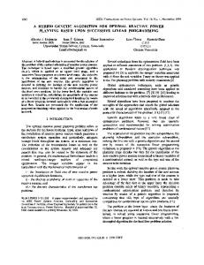
Fig. 2. Integration of proposed optimization based inverse kinematics with walking controllers.
penalty on the Cartesian and joint space tasks with respect to each other. And they could also be set to zero if the robot needs to be controlled only in the Cartesian or joint space. Our objective function (5) can be equivalently rewritten to the general QP form as in (1) where H = AT A, g = −AT b with the constant term 12 bT b dropped out, in order to be efficiently solved by the state of art QP solvers (e.g. qpOASES [16]). We choose this structure which considers Cartesian and joint space tasks at the same time for computational efficiency. Different tasks could be solved simultaneously and influence the robot behavior according to their objective weight coefficients. Another approach to the use of the robot’s redundancy for different tasks is to adopt a prioritization scheme, which solves a number of tasks in order according to their priorities. Take the cross-legged walking as an example, this type of scheme, e.g. Stack of Tasks [17], could realize selfcollision avoidance by ranking the self-collision avoidance in a higher priority than others, e.g. reference tracking tasks. However, at every hierarchy level, the QP problem needs to be solved once. Therefore, the computational cost increases considerably according to the number of tasks, which makes them not a suitable for dynamic locomotion tasks given a restricted sampling time. 1) Cartesian Space Tasks: The main Cartesian space objective is to track the desired end-effector velocities. Therefore, we penalize the deviations from references by Acart = We J ∈ R6m×n , bcart = [x˙ T1 x˙ T2 · · · x˙ Tm ]T
6m
∈R ,
(8)
where J ∈ R is the Jacobian matrix composed of all end-effectors’ Jacobian matrices in the form of J2T
···
T T Jm ] ,
des fk x˙ i = x˙ des i + Kcart (xi − xi )
Ji ∈ R6×n .
(9)
We ∈ R6m×6m is a diagonal weight matrix for weighting each Cartesian DoF of end-effectors in the final objective. Small weight means that precise tracking is less critical of that particular DoF compared to those with higher weights.
∈ R6 ,
(10)
where xdes and x˙ des are the desired Cartesian space posture i i and velocities, xfki is the real end-effector posture calculated by the forward kinematics using the link-side encoders feedback. By introducing the actual robot states to construct the Cartesian space task, the convergence to the desired Cartesian targets is achieved. To generate the desired Cartesian space posture and velocities for two feet during walking, as shown in Fig. 2, the gait pattern generator firstly takes the footstep references as inputs, then generates desired Cartesian positional trajectories using a receding horizon control scheme, e.g. preview controller [14]. Combining the CoM modifications generated ˙ des by the stabilizer [19], xdes feet and xfeet are therefore obtained by transforming the desired Cartesian trajectories from global frame to the pelvis base frame. Hence, all these Cartesian space variables are described in the base frame which is located at the pelvis center, and all the Jacobian matrices are computed from pelvis to the end-effectors. After solving the QP problem with the objective function (5), the optimized joint velocities q˙ ∗ are integrated to obtain the joint position references q ∗ for the position-controlled robot. The Cartesian velocity errors of ith end-effector, which are represented by the optimized joint velocities q˙ ∗ , e˙ i = Ji q˙ ∗ − x˙ i
(7)
6m×n
J = [J1T
In other words, such Cartesian DoFs with low weights could be deviated more in the task space and therefore enlarge the solution space for satisfying other objectives/constraints, e.g. collision avoidance. The default We is an identity matrix which means all the Cartesian DoFs have the same weight in the task space objective. It can be configured to allow changes in more flexible Cartesian DoFs in different tasks. For instance, when the leg needs to perform self-collision avoidance during swinging, it is permitted to deviate from the references, and it has to return back to the reference before landing. Therefore, the weights of the corresponding swing foot DoFs in We are set to small values during swinging to avoid collisions, and transit back to default ones at the beginning and end of swinging to minimize the tracking errors of the swing trajectory. The transition of weights between two sets of values is smoothly and continuously implemented by a third order polynomial. For each end-effector, using the velocity-based control law introduced in [18], the reference Cartesian targets x˙ i are defined as
∈ R6 ,
(11)
could be further used for landing position modification in Section II-B. 2) Joint Space Tasks: The joint space objectives are formed as nt X Ajnt = ai Ui ∈ Rn×n , (12)
1028
i=1
bjnt =
nt X i=1
ai ui
∈ Rn ,
(13)
Pnt ai = 1, where ai is the weight for ith joint space task, i=1 Ui ∈ Rn×n is the selection matrix for ith joint space task, Ui = I means all the joints are selected for this task and I is the identity matrix. ui ∈ Rn are the various specified joint space targets and nt is the total number of the joint space tasks. One example of the joint tasks is the manipulability measure proposed in [20] which describes the distance to singular configurations. The manipulability gradient objectives are introduced to avoid singularity during motion, which have the form of Umani = I ∈ Rn×n , umani = ∇f (q) ∈ Rn ,
(14) (15)
where f (q), the function of joint configuration q f (q) =
m X p
∈ Rn
det(Ji JiT )
(16)
i=1
is the sum of all end-effectors’ manipulabilities. The joint velocities could also directly track the references by setting Udir = I ∈ Rn×n , udir = q˙ref ∈ Rn ,
(17) (18)
where the reference joint velocities q˙ref can be derived from the desired joint angles and velocities, and actual joint angles similar to (10). This objective could also be treated as a Tikhonov Regularization term by setting q˙ref = 0 to make the QP problem well-conditioned. We also penalize the changes of joint velocities in order to eliminate high frequency oscillations [21], Uprev = I ∈ Rn×n , ∗ uprev = q˙prev ∈ Rn ,
(19) (20)
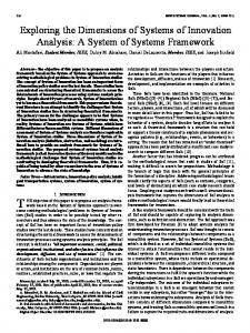
∗ where q˙prev are the optimized joint velocities from the previous time step. 3) Collision Avoidance Constraints: The method named Velocity Damper [22] is introduced for collision avoidance. As shown in Fig. 3, the distance of two moving objects d is defined as the distance between two closest points p1 and p2 of them. If the two objects are moving closer to each other, the velocity of d is defined as
d − ds , d˙ ≥ −ξ di − ds
for d < di ,
(21)
where ξ is the positive damping coefficient. ds , the security distance, is the minimum distance that d could be. This inequality implies that, when d is smaller than influence distance di , two objects will try to decrease the convergence velocity and to prevent themselves to be too close since d could never be smaller than ds . Computing d˙ using the current configuration and the joint velocities, the Velocity Damper inequality becomes nT (Jp1 − Jp2 )q˙ ≥ −ξ
d − ds , di − ds
for d < di ,
Moving Object
O1
p1
p2
Moving Object
ds
O2
di Fig. 3.
Velocity damper constraint.
where n = (p1 − p2 )/ kp1 − p2 k is the normal vector from p1 to p2 . Jp1 and Jp2 are the Jacobian matrices at p1 and p2 computed by the forward kinematics using the link encoders feedback, respectively. The robot segments are modeled as Swept Sphere Volumes [23] for efficient computation of d with sufficient accuracy. Note that (22) is the collision avoidance constraint only for one pair of objectives. In a multi-body system such as a humanoid robot, the number of these constraints increases significantly and so does the computational cost. Therefore, careful selection of collision detection pairs needs to be taken into account. For instance, each leg is considered to consist of four segments: thigh, calf, ankle and foot. In case of lowerbody self-collision detection, only the 7 pairs of thigh-thigh, calf–calf, calf–foot, ankle–foot and foot–foot between two legs are selected for self-collision detection. Assuming the firm contact between the support foot and the ground, an obstacle could be considered as a part of the support foot for collision detection. Therefore, by transforming the obstacle’s geometric shape and position into the support foot frame, the proposed method could also be used to avoid the external obstacle without any modification. Multiple obstacles could be handled in the same manner by considering them as the extended parts of the support foot. New collision detection pairs of swing foot–obstaclek , swing calf–obstaclek and swing thigh–obstaclek are appended to the inequality constraints for the k th obstacle. Rewrite (22) for ith collision detection pair as Ci q˙ ≥ ci ,
for i = 1, 2, · · · , nc ,
(23)
therefore, the collision avoidance constraints are expressed as inequality constraints (2) for the QP problem (5) as C1 c1 . nc ×n .. ∈ R , ccol = ... ∈ Rnc . (24) Ccol = cnc Cnc where nc is the number of collision detection pairs, which is 7 for the case of lower-body detection, and additional 3nobs when nobs obstacles occur in the walking path. 4) Bound Constraints: Using the same Velocity Damper method, the joint velocity limit constraints can be defined as follows,
(22) 1029
f min (qj ) ≤ q˙j ≤ f max (qj ),
for j = 1, 2, · · · , n,
(25)
where f min (qj ) and f max (qj ) are the functions of joint angle qj as follows, (qj − qj− ) − qs if qj − qj− ≤ qi −ξq min qi − qs (26) f (qj ) = q˙− otherwise j (qj+ − qj ) − qs ξq if qj+ − qj ≤ qi max qi − qs f (qj ) = (27) q˙+ otherwise j
where ξq , qi and qs corresponds to ξ, di and ds in (22), respectively. qj− and qj+ , q˙j− and q˙j+ are the robot’s lower and upper physical limits of joint angle/velocity, respectively. Therefore, a total number of n bound constraints are introduced in (3) for the QP problem (5). For locomotion tasks, no equality constraints are introduced in this particular study. However, they could be easily added to the QP formulation for specific tasks, e.g. directly enforcing desired joint angles for gaze tracking. Our study has only two legs as end-effectors, hence 12 joints are selected. The optimization problem (1) is formulated as 1 T T q˙ A Aq˙ − bT Aq˙ q˙ 2 s.t. Ccol q˙ ≥ ccol , min f (q) ≤ q˙ ≤ f max (q) ,
min
(28) (29) (30)
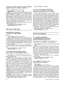
where A and b consist of both Cartesian and joint space tasks which are introduced in Section II-A.1 and II-A.2, respectively. B. Landing Position Modification The Cartesian velocity errors of swing foot e˙ SwingFoot which is calculated by (11) can be further used for modifying the landing foot position in case the collision is unavoidable during landing. Let D0 = [dx dy ] be the reference horizontal position of the next foot placement at the beginning of the swing phase, therefore, the final reference landing position at time tk = k∆t during swinging could be updated by i h ∆t 0 Dk = Dk−1 + 0 ∆t 0 e˙ SwingFoot , (31) where k ∈ 0, . . . , T∆tSS , ∆t is the time step size, TSS is the swing phase duration, e˙ SwingFoot is the relaxed Cartesian velocity errors of swing foot obtained from (11) at tk . As shown in Fig. 2, the new landing foot location Dk is therefore sent to the footstep planner to update desired footsteps for generating new gait patterns. By continuously updating the next footstep at each control loop during swinging, the swing foot will eventually land in the collision-free area. III. S IMULATIONS Several simulation studies were carried out on a childsize humanoid robot (Fig. 4) modeled in Open Dynamics Engine (ODE) to evaluate the effectiveness of the proposed optimization scheme. The simulated robot has the same kinematics, dynamics and actuator configuration of the real compliant humanoid robot COMAN, whose weight is about 32 kg, the height of the CoM is approximate 0.45 m and foot
Total mass: 34kg
Thigh length: 0.2258 m Calf length: 0.201 m
Ankle height: 0.0793 m
Fig. 4.
Joint
DOF
Neck
2
Shoulder
3
Elbow
1
Waist
3
Hip
3
Knee
1
Ankle
2
Total
25
Kinematics and actuator configuration of the ODE model.
size is 0.14 m by 0.09 m. More details of the COMAN robot could be found in [24]. The control loop ran at 200 Hz in the simulations, and the average computational time for solving the proposed optimization framework, including constructing all the objectives and collision detection pairs, was less than 1.5 ms on a desktop computer (Intel i5-4430 CPU), which is fast enough for future on-line implementation on the real robot. To eliminate the landing impacts during walking, an active compliance stabilization [19] was enabled throughout these simulations. As shown in Fig. 2, this stabilization strategy takes the desired trajectories and sensors feedback as inputs, and generates the CoM modifications using an admittance control scheme, therefore realizes compliant behavior against unexpected external disturbances. With the assistance of the stabilizer, we can focus on the evaluation of the performance of the proposed framework in the following simulations. Details of the stabilizer could be found at [19]. A. Cross-legged walking In this simulation, a cross-legged gait pattern was designed to verify the effectiveness of the proposed strategy. As shown in Fig. 5, the discrete footsteps were designed not to collide with each other, therefore, the landing position modification was not necessary. The gait pattern began with double support on the ground, and the two feet were parallel to each other with the distance of 0.1452 between their centers. The gait pattern consisted of 5 steps with the step length of 0.18 m. The first 3 steps were designed to place the foot 0.05 m close to the central line between the feet along the sagittal plane, and the gait terminated at the same double support posture as the initiation. The gait cycle was 0.9 s, the reference foot clearance was 0.05 m. The feet were designed always to be level to the ground during walking. The dash lines in Fig. 5 are the the swing foot trajectories using the conventional design, where the feet are too close during the swinging phase of the second step which will lead to a fall due to the collision. To successfully accomplish this cross-legged gait pattern, the weights of horizontal Cartesian DoFs of the swing foot in We were set to small values during swinging, meanwhile, the other components of We kept their default values. The solid lines shown in Fig. 5 were the real trajectories of the swing
1030
LeftFt Real Traj
RightFt Real Traj
LeftFt Ref Traj
RightFt Ref Traj
0.1
y [m]
0.05
5 th
0
1
st
3
rd
2 nd
-0.05
4 th
-0.1 -0.15 0
0.1
0.2
0.3
0.4 x [m]
0.5
0.6
0.7
0.8
Fig. 5. Top view of foot trajectories during cross-legged walking. The dash lines are the references, the solid lines are the measured trajectories generated by the proposed method which avoids leg collisions. LeftFt Real Traj
RightFt Real Traj
LeftFt Ref Traj
RightFt Ref Traj
0.15
Fig. 7. Snapshots of the robot walking forward without (top) and with (bottom) collision avoidance when a large obstacle occurs.
0.1 0.05
2 nd
4 th
y [m]
LeftFt Real Traj
RightFt Real Traj
LeftFt Ref Traj
RightFt Ref Traj
0 -0.05
0.1 1 st
-0.1
3 rd
0.05
y [m]
-0.15
1 st
3 rd
5 th
0
-0.2 0
0.1
0.2
0.3
0.4
0.5
0.6
0.7
-0.05
x [m] 2 nd
-0.1
Fig. 6. Top view of foot trajectories during external obstacle avoidance walking. The dash lines are the references, the solid lines are the measured trajectories generated by the proposed method which avoids collisions between swing foot and the obstacle.
foot. Note that the controller deviated the swing foot away from the support foot when they were too close, therefore the gait pattern was successfully executed without self-collisions. B. Obstacle Avoidance In this simulation, the proposed method’s ability in avoiding external obstacle was demonstrated. Here, three collision detection pairs between the swing foot and the obstacle were added into the collision avoidance constraints. Since our method is a local approach, meaning that the possible collision will only be detected when the obstacle is within one-step area, therefore, the obstacle is not yet visible until the last step. The obstacle’s information should be provided by a high level controller, e.g. perception module. As shown in Fig. 6, the robot was commanded to walk forward with the step length of 0.16 m and foot clearance of 0.05 m. An external obstacle with size of 0.02 × 0.04 × 0.18 m was placed in the walking path. A collision would occur between the right foot and the obstacle if the conventional trajectory (dash line) were performed. Furthermore, the obstacle was too tall for such a child-size humanoid robot to overstep, though it was not too wide to avoid by modifying the swing foot trajectory. Since the obstacle was regarded as a part of the support foot, the similar collision avoidance attempt of the swing foot was produced compared to the previous simulation. By introducing the proposed method, the swing foot pushed itself to the right side to avoid the collision with the obstacle. The real trajectories are plotted in solid line in Fig. 6. It
4 th
-0.15 0
0.1
0.2
0.3
0.4
0.5
0.6
0.7
x [m]
Fig. 8. Top view of foot trajectories during stepping over an obstacle of 0.1 m by 0.02 m.
should be noted that the robot deviated from the reference heading since the second step. This happened because of the angular momentum, which was generated by the collision avoiding motion of the swing foot, caused the support leg to rotate along the swing foot. Since the proposed inverse kinematics framework does not take the dynamics disturbances into consideration, a dynamic balancing strategy, e.g. momentum-based balance controller [25], would be helpful to counteract such influence as a future work. Meanwhile, excessive abduction of the swing foot led to an early landing at the third step in Fig. 6. Fig. 7 shows the snapshots of the simulated robot’s behavior without (top) and with (bottom) external obstacle collision avoidance. C. Obstacle Overstepping In this simulation study, as shown in Fig. 8, a long obstacle that the robot must overstep to pass was placed in front of the robot. It was 0.1 m high and 0.02 m wide. The robot started walking with step length of 0.1 m, then increased to 0.22 m in 3rd and 4th step in order to step over the obstacle, and changed back to 0.1 m after the overstepping. All the three translational DoFs of the swing foot were relaxed during this locomotion task. To enlarge the space for lifting the swing foot, the vertical DoF of the support leg during overstepping was also relaxed to straighten the support leg. The term “relax” here corresponds to the setting of small weights in We . As shown in Fig. 9, the solid lines are measured trajectories of hip and feet, and the dash ones
1031
0.25
Lft Lft ref
Hip Hip
0.15
0.48 ref
0.1
0.46
Hip height [m]
Feet height [m]
0.5
Rft Rft ref
0.2
0.05 0.44 0 5
5.5
Fig. 9.
6 Time [s]
6.5
7
Hip and feet height during obstacle overstepping.
LeftFt Real Traj
RightFt Real Traj
LeftFt Ref Traj
RightFt Ref Traj
0.1
y [m]
0.05
1 st
3 rd
Fig. 11. Snapshots of the robot stepping over an obstacle without (top) and with (bottom) landing position modification. The collision/modification was applied at first snapshot.
5 th
0 -0.05 2 nd
-0.1
4 th
IV. C ONCLUSION
6 th
-0.15 0
0.1
0.2
0.3
0.4
0.5
0.6
0.7
x [m]
Fig. 10. Top view of landing foot position that was modified to be placed in front of a large obstacle during walking.
are the references. Note that the planned lift height of swing foot was 0.1 m which is the same as the obstacle, directly executing the reference trajectories would definitely lead to collision. Therefore, the proposed scheme utilized the relaxed DoFs of the feet and lifted the swing foot higher over the obstacle. The raised foot clearance differences between the references and measured trajectories were benefited partly from of the swing foot vertical positional modification, and also partly from the extension of the support leg which corresponded to the hip height raise in Fig. 9. Note that the swing foot abduction strategy in [12] was not introduced in this study. The lateral modification of right foot trajectory during overstepping in Fig. 8 was guided automatically by the manipulability criterion which optimized the swing foot behavior in the joint space. It produces a similar effect as the abduction strategy increasing the lift height to avoid the leg singularity.
In this paper, a novel generic optimization based reactive collision avoidance framework is proposed for bipedal locomotion. It can modify the swing foot trajectory to avoid potential collisions either between the internal leg/foot segments or with the external obstacles by allowing the swing foot not to strictly track the planned references. The performance of the proposed method was demonstrated on the simulated COMAN by cross-legged walking and obstacle negotiations. Future work will be the experimental validation on the real robot once the system is available. More future directions could be further improvements in robot’s autonomy, e.g. high level decision making, coordination of different constraints for possible collisions, integration of visual perception for accurate environmental information, and synthesis with footstep planner to perform more versatile locomotion skills on rough terrains. ACKNOWLEDGMENT This work is supported by the FP7 European project WALK-MAN (ICT 2013-10).
In the second test, we changed the obstacle location to overlap with the 2nd reference step which is shown in dash square in Fig. 10. It was clear that changing only the swing foot trajectory could not avoid collision at the end of the swinging phase, and placing the foot to a new collision-free area became necessary. The approach introduced in section II-B was therefore used to modify the next footstep. When the right swing foot was approaching the obstacle, the new footstep was also updating to be in front of the obstacle. As shown in Fig. 10, the robot finally stepped at the 2nd solid square, and then stepped over the obstacle similar to the first test, and kept walking forward with the original gait pattern. 1032
R EFERENCES [1]
[2] [3]
[4]
[5]
S. Kajita, F. Kanehiro, K. Kaneko, K. Yokoi, and H. Hirukawa, “The 3d linear inverted pendulum mode: a simple modeling for a biped walking pattern generation,” in IEEE/RSJ International Conference on Intelligent Robots and Systems, vol. 1, 2001, pp. 239–246. H. Seraji and B. Bon, “Real-time collision avoidance for positioncontrolled manipulators,” IEEE Transactions on Robotics and Automation, vol. 15, no. 4, pp. 670–677, 1999. H. Sugiura, M. Gienger, H. Janssen, and C. Goerick, “Real-time self collision avoidance for humanoids by means of nullspace criteria and task intervals,” in IEEE-RAS International Conference on Humanoid Robots, 2006, pp. 575–580. O. Stasse, A. Escande, N. Mansard, S. Miossec, P. Evrard, and A. Kheddar, “Real-time (self)-collision avoidance task on a hrp-2 humanoid robot,” in IEEE International Conference on Robotics and Automation, 2008, pp. 3200–3205. J. Kuffner, K. Nishiwaki, S. Kagami, Y. Kuniyoshi, M. Inaba, and H. Inoue, “Self-collision detection and prevention for humanoid robots,” in IEEE International Conference on Robotics and Automation, vol. 3, 2002, pp. 2265–2270.
[6]
[7]
[8]
[9] [10] [11] [12]
[13]
[14]
[15] [16]
[17]
[18]
[19] [20] [21] [22]
[23] [24]
[25]
F. Kanehiro, M. Morisawa, W. Suleiman, K. Kaneko, and E. Yoshida, “Integrating geometric constraints into reactive leg motion generation,” in IEEE/RSJ International Conference on Intelligent Robots and Systems, 2010, pp. 4069–4076. J. Chestnutt, M. Lau, G. Cheung, J. Kuffner, J. Hodgins, and T. Kanade, “Footstep planning for the honda asimo humanoid,” in IEEE International Conference on Robotics and Automation, Apr. 2005, pp. 629–634. K. Sabe, M. Fukuchi, J.-S. Gutmann, T. Ohashi, K. Kawamoto, and T. Yoshigahara, “Obstacle avoidance and path planning for humanoid robots using stereo vision,” in IEEE International Conference on Robotics and Automation, vol. 1, Apr. 2004, pp. 592–597. R. Deits and R. Tedrake, “Footstep planning on uneven terrain with mixed-integer convex optimization,” in IEEE-RAS International Conference on Humanoid Robots., Nov. 2014, pp. 279–286. Y. Guan, E. Neo, K. Yokoi, and K. Tanie, “Stepping over obstacles with humanoid robots,” IEEE Transactions on Robotics, vol. 22, no. 5, pp. 958–973, 2006. O. Stasse, B. Verrelst, B. Vanderborght, and K. Yokoi, “Strategies for humanoid robots to dynamically walk over large obstacles,” IEEE Transactions on Robotics, vol. 99, pp. 1–8, 2009. C. Zhou, X. Wang, Z. Li, D. Caldwell, and N. Tsagarakis, “Exploiting the Redundancy for Humanoid Robots to Dynamically Step Over a Large Obstacle,” in IEEE/RSJ International Conference on Intelligent Robots and Systems, Hamburg, Germany, Sep. 2015, pp. 1599–1604. A.-C. Hildebrandt, D. Wahrmann, R. Wittmann, D. Rixen, and T. Buschmann, “Real-time pattern generation among obstacles for biped robots,” in IEEE/RSJ International Conference on Intelligent Robots and Systems, 2015, pp. 2780–2786. S. Kajita, F. Kanehiro, K. Kaneko, K. Fujiwara, K. Harada, K. Yokoi, and H. Hirukawa, “Biped walking pattern generation by using preview control of zero-moment point,” in IEEE International Conference on Robotics and Automation, vol. 2, 2003, pp. 1620–1626. S. Kajita, H. Hirukawa, K. Harada, and K. Yokoi, Introduction to Humanoid Robotics, ser. Springer Tracts in Advanced Robotics. Springer, 2014, vol. 101. H. Ferreau, C. Kirches, A. Potschka, H. Bock, and M. Diehl, “qpOASES: a parametric active-set algorithm for quadratic programming,” Mathematical Programming Computation, vol. 6, no. 4, pp. 327–363, 2014. N. Mansard, O. Stasse, P. Evrard, and A. Kheddar, “A versatile generalized inverted kinematics implementation for collaborative working humanoid robots: the stack of tasks,” in International Conference on Advanced Robotics, 2009, pp. 1–6. J. Nakanishi, R. Cory, M. Mistry, J. Peters, and S. Schaal, “Operational space control: a theoretical and empirical comparison,” The International Journal of Robotics Research, vol. 27, no. 6, pp. 737–757, 2008. C. Zhou, Z. Li, X. Wang, N. Tsagarakis, and D. Caldwell, “Stabilization of Bipedal Walking Based on Compliance Control,” Autonomous Robots, pp. 1–17, Nov. 2015. T. Yoshikawa, “Manipulability of robotic mechanisms,” The international journal of Robotics Research, vol. 4, no. 2, pp. 3–9, 1985. S. Feng, E. Whitman, X. Xinjilefu, and C. G. Atkeson, “Optimization-based full body control for the darpa robotics challenge,” Journal of Field Robotics, vol. 32, no. 2, pp. 293–312, 2015. B. Faverjon and P. Tournassoud, “A local based approach for path planning of manipulators with a high number of degrees of freedom,” in IEEE International Conference on Robotics and Automation., vol. 4, Mar. 1987, pp. 1152–1159. E. Larsen, S. Gottschalk, M. C. Lin, and D. Manocha, “Fast proximity queries with swept sphere volumes,” Department of Computer Science, University of North Carolina, Tech. Rep. TR99-018, 1999. N. Tsagarakis, S. Morfey, G. Medrano-Cerda, Z. Li, and D. Caldwell, “Compliant humanoid coman: optimal joint stiffness tuning for modal frequency control,” in IEEE International Conference on Robotics and Automation, 2013, pp. 665–670. S.-H. Lee and A. Goswami, “A momentum-based balance controller for humanoid robots on non-level and non-stationary ground,” Autonomous Robots, vol. 33, no. 4, pp. 399–414, 2012.
1033