Algorithm. Keywords. Honeycomb, mapping, REDEFINE, Cayley graph, Cayley tree ..... the 19th IEEE International Conference on Application specific. Systems ...
©2010 International Journal of Computer Applications (0975 - 8887) Volume 1 – No. 21
A Generic Graph-Oriented Mapping Strategy for a Honeycomb Topology Gaurav Kumar Singh, Mythri Alle, Keshavan Vardarajan, S K Nandy Indian Institute of Science, Bangalore
Ranjani Narayan Morphing Machines, Bangalore, India
ABSTRACT REDEFINE [3] is a polymorphic ASIC, in which arbitrary computational structures on hardware are defined at runtime. The REDEFINE execution fabric comprises Compute Elements (CEs) interconnected by a Honeycomb network, which also serves as the distributed Network-on-chip. Each computational structure is dynamically assigned to a subset of the CEs on the execution fabric by the REDEFINE support logic. A HLL specification of the application is compiled into Hyper Operations (HyperOps) by the REDEFINE compiler [3], where each HyperOp is a set of interacting operations. The compiler also determines partitions of the HyperOps (pHyperOps) that can be assigned to CEs to suitably meet the structural constraints of the execution fabric. In this paper we propose an algorithm to map HyperOps onto Computational Structures. A pHyperOp communication graph (PCG) captures the communication between the various pHyperOps. Through a sequence of transformations, the PCG is transformed into a Cayley tree. The Cayley tree is then overlayed on the Cayley graph to form a computational structure. The proposed mapping algorithm offers a solution that incurs a penalty 18% on average over that of the optimal.
Categories and Subject Descriptors G.2.2 [Mathematics of Computing]: DISCRETE MATHEMATICS—Graph Theory
General Terms Algorithm
Keywords Honeycomb, mapping, REDEFINE, Cayley graph, Cayley tree
1. INTRODUCTION AND MOTIVATION On the architecture front, ever changing requirements of applications in terms of power, performance and throughput have demanded reconfigurable architectures in contrast to ASIC solutions due to prohibitive cost of ASICs. One such reconfigurable architecture REDEFINE by Alle et al. [3] serves a range of applications from a domain. This architecture comprises homogeneous set of Compute Elements (CEs) connected by a Network-on-chip (NoC). NoC is a novel approach to establish inter-chip communication based on data communication network. One of the influencing factors in energy
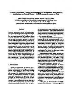
consumption, latency and other performance parameters of NoC is topology. A special class of networks, called symmetric interconnection networks has been widely used for the purpose. The property of such network is that the network viewed from any vertex of the network looks the same. In such a network, congestion problems are minimized since the load is distributed uniformly through all vertices. Moreover, this symmetry allows for identical routers at every vertex with identical routing algorithms. It is also very useful in designing algorithms that exploit the structure of the network. In designing symmetric interconnection networks, the overall objective has been to construct large vertex symmetric graphs with small degree and diameter, high connectivity, and offering simple routing algorithms. Examples of this network are mesh, honeycomb, etc. Honeycomb has a lower degree per node than a 2-D Mesh [12]. This reduces the complexity and area of the network router. A detailed comparison of the honeycomb and mesh topologies is provided in [13]. The architecture REDEFINE in [3] uses Honeycomb topology as its underlying NoC. REDEFINE [3,12] hardware resources, comprise Compute Elements (CEs) with local storage and routers that communicate over network on chip (NoC) as in Fig. 1. Resources are controlled by the Support Logic. The Support Logic comprises HyperOp Launcher (HL), Load Store Unit (LSU), Inter HyperOp Data Forwarder (IHDF), Hardware Resource Manager (HRM) and Resource Binder (RB). In [4], functional description of these modules is briefly provided. In REDEFINE, diverse data paths are composed in terms of computational structures at runtime. A computational structure is a physical aggregation of hardware resources that can perform a coarse grained operation, referred as a Hyper Operation (HyperOp). Compiler for REDEFINE, compile applications to an intermediate form and convert it into dataflow graphs [3]. These dataflow graphs are directed graphs of nodes where each node represents a HyperOp. Each HyperOp comprises multiple fine grained operations. In order to exploit parallelism that exists within a HyperOp (also due to storage limitation in a CE), each HyperOp is divided into several partitions (pHyperOp) and each pHyperOp is assigned a CE. Compiler captures the computation to be performed by each pHyperOp in terms of compute metadata and the inter/intra HyperOp communication in terms of transport metadata. The exact CEs to which HyperOps need to be loaded, is determined by the Resource Binder (RB). RB does this by, first maintaining a list of status (busy/idle) of all CEs and then by finding the appropriate place for each HyperOp. RB loads HyperOps in accordance to configuration matrix provided by compiler. Configuration matrix holds the information of relative positioning of nodes. Generation of configuration 91
©2010 International Journal of Computer Applications (0975 - 8887) Volume 1 – No. 21 matrix requires the embedding of nodes of PCG as per the architectural constraint of NoC. This embedding is needed primarily due to mismatch between the communication patterns among different modules of an application and the topology of the NoC. The problem hence translates to embedding an application represented by a source graph, G (that captures the communication patterns among modules of the application) onto a destination graph, H that depicts the topology of the NoC. In set theoretic definition, this is equivalent to assigning to each vertex u of G, a single vertex f(u) in H and each edge (u,v) of G to a path between f(u) and f(v) in H. This path may have intermediate vertices between f(u) and f(v). The general mapping problem is (unfortunately) an NP-hard combinatorial optimization problem, thus inherently intractable as shown by Johnson [2]. This necessitates the elaboration of efficient heuristics. Some of the earlier heuristics in Sarkar [9] and Gerasoulis [10] have used clustering of nodes in the source graph before physical mapping onto the target graph (in the case of source graph having more nodes than target graph).
Figure 1: Architecture of REDEFINE In this paper we present an embedding of a general graph into a honeycomb, with a constraint of one-to-one mapping of source graph to the target graph. Our embedding technique, called GOMAP (Graph Oriented Mapping) takes PCG generated by the compiler of REDEFINE [3] as source graph (limited to 16 nodes) and maps it onto the honeycomb network topology of the architecture. We also discuss the format of configuration matrix and processing of this matrix by RB. The remainder of this paper is as follows: Section 2 reviews the graph models for source graph, target (destination) graph as well as cost function for evaluating physical mapping. We have defined the case of
optimality and cost overhead for mapping with respect to this cost function. We have also introduced the terminology of Cayley graph and Cayley tree in the section. Section 3 outlines the approach and steps of proposed algorithm. Section 4 gives an example on proposed method. In section 5 the experimental results of proposed algorithmic approach are presented in comparison with optimal in terms of communication overhead for honeycomb. In Section 6 we conclude our approach and give perspectives into future work.
2.
GRAPH MODEL
Application of graph theory to finding mapping of a source graph to a destination graph is well known [8]. We will represent the source graph as Gs (Vs , Es ) and the target graph as Gd (Vd , Ed ). We use the term “Hop" to indicate the unit distance between any two directly connected nodes in the target graph. The “distance" between two compute nodes u and v is the number of hops in the shortest path connecting u and v. Definition 1: The source graph is an undirected graph, Gs (Vs ,Es) where each vertex vi Vs represents a node and the edge (vi, vj ), denoted as ei,j Es , represents the communication between vi and vj. The weight of the edge ei,j denoted by commi,j , represents the total number of communication between the two nodes. An example of source graph is Fig. 2.
Figure 2: Communication graph of 6 Nodes
Definition 2: The target graph is an undirected graph Gd (Vd ,Ed ) where each vertex vi Vd represents a node in topology and the direct edge (vi , vj) denoted as ei,j represents the hop distance of one, between the two nodes. Source graph is a weighted graph, so we use adjacency matrix representation for weights. For example, adjacency matrix representation for weights of Fig. 2 is in Table 1. Table 1: Adjacency-Matrix Representation for Weighted 92
©2010 International Journal of Computer Applications (0975 - 8887) Volume 1 – No. 21 Graph Node 0 1 2 3 4 5
0 0 0 8 6 4 3
1 0 0 0 0 0 1
2 8 0 0 5 7 2
3 6 0 5 0 5 0
4 4 0 7 5 0 4
5 3 1 2 0 4 0
2.1 Mapping Formulation The mapping of the source graph Gs (Vs , Es) onto the target graph Gd (Vd , Ed ) is defined by an injection function map fmap : Vs → Vd , s.t map (vs ) = vd , ∀ vs ∈ Vs , ∃!vd ∈ Vd , where | Vs |≤| Vd |
2.2 Cost Function Formulation To evaluate our technique, we define a Cost Function (CF), similar to the kind of cost function used in Koziris [5] and Zhonghai [6]. CF(fmap ) =
Σ dist(f
map (us ), fmap (vs )) × comm(us , vs)
where: • dist(fmap (us), fmap (vs)) gives the shortest distance between the two nodes (ud ,vd) in target graph onto which nodes (us ,vs) in the source graph are mapped. • comm(us,vs) is the weight of the edge e(us,vs) in the source graph. Our objective is to find the mapping fmap which minimizes CF( fmap ). We also define case of optimality for fmap(optimal) as :
Figure 3: Honeycomb as Representation of Cayley Graph Cayley tree is a connected cycle-free graph where each non-leaf node is connected to Z neighbors, where Z is called the coordination number. This can be viewed as a tree-like structure emanating from a central node, with all the nodes arranged in concentric shells around the central node. The central node is termed as root or origin. Ancestor and descendant relationships in the Cayley tree are defined relative to the root.
CF(fmap(optimal)) = min { CF(fmap) ∀ fmap ∈ M APALL } where MAPALL is the set of all possible mapping exist for this particular target graph • Cost Overhead of mapping is defined in comparison to optimal as follows:
Cost Overhead =
CF(fmap) - CF(fmap(optimal) CF(fmap(optimal)
X 100 %
2.3 Cayley Graph and Cayley Tree In section 1 we mentioned that our target graph is a honeycomb network, which is a symmetric interconnection network. From group theory perspective, honeycomb networks come under a special type of algebraic model, called Cayley graph (see Fig. 3). Krishnamurthy [1] discusses Cayley Graph and describe its properties in terms of degree, diameter, connectivity and routing algorithms.
Figure 4: Cayley Tree (Bethe Lattice) of degree 3 The number of nodes in the kth shell is given by, Nk = Z(Z-1)k-1 for k > 0 A star type Cayley tree of degree 3, also known as Bethe lattice [7] of coordination number 3 is shown in Fig. 4. Levels in Cayley graph and Cayley tree are defined with respect to root as concentric circles as shown by dotted circles in Fig 3 and Fig 5. For example, in Fig 3 node 0 is at level 0, nodes 1, 2, 3 are at level 1. The use of Cayley tree and Cayley graph is in section 3.
93
©2010 International Journal of Computer Applications (0975 - 8887) Volume 1 – No. 21
3. THE GRAPH ORIENTED MAPPING ALGORITHM (GOMAP) Primary objective of our heuristic is to minimize the cost function. In order to do this, our approach is to place the nodes of the source graph as close as possible in the target graph. In other words, we start with the node which has maximum communication with its neighbors and map it to a vertex in the target graph. We then place nodes having direct communication with this node close to it (on the target graph), in the descending order of communication. We iteratively repeat this procedure for all the nodes that are already mapped onto the target graph and stop the procedure when all the nodes of the source graph are mapped onto the target graph. There could be conflicts arising during this procedure, which will be resolved in accordance with the steps described in this section. As mentioned in section 2, honeycomb topology is a Cayley graph of degree 3 and is a graph having the following property: i) root node (node 0 in Fig. 3) at center with three edges emanating from the it, ii) for all nodes, that are independent (only one immediate ancestor) children (node 1,2), two edges emanate from that node, iii) for all other nodes that are shared (two immediate ancestors) children (node 10,13), only one edge emanate from that node, iv) there exists cycles of length 6 nodes and every node of a cycle is part of two other different cycles of length 6.
Figure 6: Conflict Scenario start from the source graph and construct an intermediate representation as close a Cayley tree as possible. We term this intermediate representation as MAP-Tree, which is constructed incrementally by best-fitting two highly communicating nodes (in the source graph) as close as possible in the target graph. Our mapping algorithm comprises three phases. In the first phase, MAP-Tree is constructed. In the second phase, conflicts arise in MAP-Tree, due to relaxation of property (iii) and (iv) of Cayley graph, are resolved and in the final phase, mapping information is generated and physical placement of compute nodes is done.
3.1 First Phase: MAP-Tree Construction Initially there is no mapping on NoC architecture tiles, and with nodes mapping, the possibility of better mapping would be decreased, nodes with higher commi,j should be mapped earlier. At first the root with the highest priority for MAP-Tree is determined by the function highest-priority(vj). highest-priority(vj) = maxj(comm(vi,vj)), vi Vs
Figure 5: Cayley Tree Representation from a Cayley Graph Perspective Property (i) and (ii), gives the basis for construction of Cayley tree of degree 3. From this we deduce that, in a Cayley graph, if we relax property (iii) and (iv) among nodes, then Cayley tree data structure can be applied for the purpose of mapping onto Cayley graph. Refer Fig. 5 for an illustration of the same. With this basis we go in detail of our mapping formulation. We will discuss relaxation of (iii) and (iv) later (3.2) in this section. Approach is to Figure 7: Different Conflict Cases of MAP-Tree Then the function finds the highest commi,j , between the source (root node in MAP-Tree) and its edge destination. 94
©2010 International Journal of Computer Applications (0975 - 8887) Volume 1 – No. 21 The node with higher ranking(vj) will be selected as the first choice. Ranking(vj) = maxj (comm(vi,vj)),
vi
MAP-Tree and vj / MAP-Tree We iteratively calculate the Ranking of each vj ( Vs ) and not in MAP-Tree with respect to the nodes vi MAP-Tree and incrementally add the selected vj in MAP-Tree with the edge(vi,vj). If degree of vi is 3, we select the descendants(k,m) of vi and compute sum of remaining communications, which have not been considered for MAP-Tree, individually for both k and m. Select node with lower sum under constraint degree[selected node] < 3. If constraint not fulfilled, repeat for other node. If none applies iterate this until we find one descendant node (say p). Then we add vj with edge(p,vj). We repeat this for each node vj in source graph Gs (Vs ,Es ) that are not in MAP-Tree. Pseudo code for MAP-Tree construction is given in Algorithm 1. function MAPTreeConstruction(Gs (Vs , Es ),T(V,E) ) /* Root Selection */ root ← highest-prioirty(vs ∈ Vs ); /* Include Root in MAP-Tree */ V ← V ∪ {root}; Vs ← Vs - V; /* Find highest communicative between root and all it descendants */ for Each descendant vs of root in Gs (Vs , Es ) do Ranking(vs ) = comm(root,vs ) ∀ vs ∈ Vs endfor /* Select the highest ranked node. Add it to MAP-Tree */ vhrank ← highest{ Ranking(vs ) }; Vs ← Vs - vhrank ; V ← V U{ vhrank}; E ← edge(root, vhrank ); while Vs != φ do foreach descendant(vi ) of VMAP−Tree ∈ V in Gs (Vs ,Es ) do Ranking(vi ) = comm(VMAP−Tree ,vi ) ∀ vi ∈ Vs endfch /* Select the highest ranked node. Add it to MAP-Tree */ vhrank ← highest{ Ranking(vi }; Vs ← Vs - vhrank ; V ← V U {vhrank }; vsource ← (node in MAP-Tree that has highest communication with vhrank ); if degree[vsource ]