A Genetic Algorithm for Automatic Generation of Test Logic for Digital Circuits Fulvio CORNO, Paolo PRINETTO, Matteo SONZA REORDA Politecnico di Torino Dipartimento di Automatica e Informatica Torino, Italy Abstract* Testing is a key issue in the design and production of digital circuits: the adoption of BIST (Built-In SelfTest) techniques is increasingly popular, but sometimes requires efficient algorithms for the automatic generation of the logic which generates the test vectors applied to the Unit Under Test. This paper addresses the issue of identifying a Cellular Automaton able to generate input patterns to detect stuck-at faults inside a Finite State Machine (FSM). A suitable hardware structure is first identified. A Genetic Algorithm is then proposed, which directly identifies a Cellular Automaton able to reach a very good Fault Coverage of the stuck-at faults. The novelty of the method consists in combining the generation of test patterns with the synthesis of a Cellular Automaton able to reproduce them. Experimental results are provided, which show that in most of the standard benchmark circuits the Cellular Automaton selected by the Genetic Algorithm is able to reach a Fault Coverage close to the maximum one. Our approach is the first attempt of exploiting evolutionary techniques for identifying the hardware for input pattern generation in BIST structures.
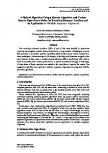
monly used, especially for Finite State Machine (FSM) synthesis. Deeply embedded, automatically synthesized FSMs acting as Control Units can often be found in current designs, and resorting to BIST is an attracting approach for their test. Fig. 1 shows the structure of a BIST circuit (or macro): during the normal working mode, the Unit Under Test (UUT) is fed with the values coming from the circuit Primary Inputs and its outputs drive the circuit Primary Outputs. When the Test Mode is selected through the Normal/Test signal, the UUT is fed by a special circuitry named Input Pattern Generator producing the vectors which activate the possible faults inside the UUT. The Output Data Evaluator checks whether the output behavior of the UUT matches the expected values. The BIST Controller manages the whole test circuitry and possibly generates the Good/Faulty signal to the outside. Primary Inputs Input Pattern Generator MPX Normal/Test
UUT
1. Introduction Built-In Self-Test (BIST) [ABFr90] has been widely recognized as an effective approach for testing of Application Specific Integrated Circuits (ASICs). In the last decade, successful adoption of BIST has been reported for circuits as a whole and for embedded macros. In the meantime, design techniques evolved significantly, and automatic synthesis tools are now com*
This work has been partially supported by Italtel. Contact address: Matteo SONZA REORDA, Dipartimento di Automatica e Informatica, Politecnico di Torino, Corso Duca degli Abruzzi 24, I-10129 Torino (Italy), e-mail
[email protected]
BIST Controller
Good/Faulty
Output Data Evaluator
Primary Outputs
Fig. 1: Architecture of a BIST circuit. One of the today main issues in the BIST area is how to exploit BIST to test embedded FSMs, facing the problems coming from their limited accessibility and their highly sequential behavior. Several solutions have been proposed: partial and full scan [Jett95], CSTP [KrPi89], BILBO [KMZw79]. Most of the approaches tend to transform the circuits
into combinational ones. Their effectiveness can be evaluated from many points of view: how much area and performance overhead they introduce, which fault coverage they guarantee, how easily and automatically they can be introduced into the original design structures, etc. When devising a BIST technique, two main issues have to be addressed: how to generate the test patterns, and how to evaluate the output behavior. When FSMs are not transformed into combinational circuits during test, the former issue is by far the most critical one, as many faults can be detected only provided that specific sequences are applied to the inputs. These sequences can be generated by Automatic Test Pattern Generators, but hardware structures able to reproduce them (e.g., based on ROMs) are very expensive from the area and performance points of view. Cellular Automata (CA) have been already proposed as random input pattern generators [HMPM89] and for reproducing deterministic unordered input vectors [BoKa95] [SCDM94]. Previous attempts to exploit CA to reproduce deterministic ordered input vectors [BoKa95] limited themselves to prove the difficulty of attaining any useful result. Some experimental results we gathered confirm that it is very difficult to identify any CA able to reproduce a given sequence, when this is longer than some tens of vectors. In this paper we propose a new solution to the problem of automatically synthesizing CA for input vector generation for FSMs. Previous approaches assume that suitable input sequences (e.g., generated by an Automatic Test Pattern Generator, or ATPG) are available, and describe how the logic implementing an Input Pattern Generator (IPG) able to generate them can be synthesized (Fig. 2.a). The main novelty of our approach is in combining the ATPG and IPG synthesis steps (Fig. 2.b). In this way, a single process is activated, focused at generating an effective hardware structure for the IPG; the process is similar to an ATPG one, in that it aims at reaching the highest fault coverage; however, a hardware structure is generated, instead of a test sequence. A Genetic Algorithm (GA) is adopted for this task. Furthermore, we propose a new architecture for the synthesized CA able to generate longer ordered sequences than traditional solutions. Our approach does not require transforming the circuit, but just adding the BIST logic. Section 2 reports some basics about CA and describes the hardware structure we adopted. Section 3 describes the Genetic Algorithm we devised for the automatic synthesis of the Cellular Automaton starting from the netlist of the addressed FSM. Section 4 re-
ports some preliminary experimental results, and Section 5 eventually draws some conclusions.
Circuit
ATPG Input Vectors IPG Synthesizer
Circuit
ATPG
IPG Synthesizer
Modified Circuit
Modified Circuit
(a)
(b)
Fig. 2: Proposed approach with respect to traditional one.
2. Cellular Automata Due to their versatility and ease of reconfiguration, in this paper we investigate the use of Cellular Automata for implementing IPG blocks. A cellular automaton [ToMa87] is a system composed of cells, whose behavior advances in time in discrete steps. Cells are connected in regular structures (grids), where the cells directly connected to a given cell are referred to as its neighbors. A state is associated to each cell. Each cell communicates its present state to its close neighbors and computes its new state from its current state and from that of its neighbors. The new state computation law is given by a rule [Wolf83] characterizing each cell in the system. In the case of binary Cellular Automata, the state of each cell can be either 0 or 1: in this case the evolution rule is best expressed as a truth table, which lists the new state of the cell as a Boolean function. These truth tables are often expressed as decimal numbers, by interpreting them as a binary code. The behavior of a CA can therefore be specified by giving: • the structure of the interconnection grid. The most used are one-, two- or three-dimensional square grids, but hyper-cubes, triangulated meshes, and trees can also be found.
Stage i s11 s1n s2n
s1i-1
s1i
s1i+1
… s21
s1
… s2i-1
s2i
s2i+1
Row 1
s1n
s2n
1
s2 1
Row 2
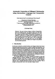
Fig. 3: Proposed CA structure.
• the neighborhood of each cell. Given a grid, the neighborhood is usually defined as the set of unit distance cells, where the distance is usually counted as the number of hops over the grid. • the boundary conditions. Whenever the grid is not infinite, boundary conditions specify how the neighborhood of boundary cells (that would otherwise be incomplete) should be constructed. Null boundary conditions (i.e., assuming that the grid is surrounded by cells whose state is invariably zero) or cyclic boundary conditions (i.e., assuming that the CA grid is circular, and that cells lying on opposite boundaries of the grid are adjacent) are usually adopted. • the evolution rules for each cell in the grid. A CA is defined as uniform when all of his cells follow the same evolution rule. More often, cells follow different rules, taken from the whole space of admissible functions or from some subset of functions with particular properties. • the initial conditions. It is usually assumed that the evolution of the CA starts from some predetermined configuration. When cellular automata are adopted as input pattern generators, a mapping between CA cells and Primary Inputs of the circuit must be established. Usually, onedimensional CA with one cell for each circuit input are adopted. In this case each cell has two neighbors, and therefore its next state is determined as a Boolean function of 3 bits: the present state of the cell and that of its neighbors. The rule of each cell is therefore selected among a set of 2^(2^3)=256 different Boolean functions. Experimental evidence shows that CA built in this way are not powerful enough to generate ordered sequences, necessary to test sequential circuits. As an
example, it is impossible to repeat any single input vector at a later time [BoKa95] without repeating all the following ones. To improve the ability of the CA to generate complex sequences, its intrinsic memory must be increased. Two possibilities can be exploited: • a one-dimensional structure with more than one cell for each circuit input. A common case is to add a dummy cell for every real CA cell. The state of dummy cells is not fed into the circuit, rather it contributes to the global state of the CA and enhances its properties. Experimental results show again that this is not a general solution. • a two-dimensional structure can be explored, where the X-dimension is given by the number of inputs, while the Y-dimension gives the extra memory. Due to the increased number of cells and the number of neighbors (4 or 8, depending on the grid), this solution usually gives a very high area overhead. In this paper, a hybrid solution is proposed. If n is the number of Primary Inputs of the circuit, we build a 2×n CA. The two-dimensional grid (Fig. 3) has therefore only two rows. To further simplify the hardware implementation, only cells on the second row are connected to circuit inputs, while cells on the first row are forced to evolve according to a fixed rule. This rule corresponds to copying the previous state of the corresponding cell in the second row: with this choice, the first row of cells just remembers the previous state of all the second row cells. Each cell in the second row has a 5-cell neighborhood, consisting of the adjacent cells on its row and on the first row: each cell has therefore access to the present state and to the previous state of itself and its right and left neighbors. Cyclic boundary conditions are assumed. For the sake of simplicity, in the following the term stage is used to
indicate the two cells in the same column. The behavior of each stage (Fig. 4) is defined by the Boolean function fi which computes the evolution rule for the lower cell. With this choices, for an n-input circuit, 2n flipflops are used, but only n cells need combinational logic for their new state function fi to be implemented. Each of the n cells of the second row is specified by a Boolean function selected in a space of 2^(2^6)= 1.84×10¹⁹ different ones.
3. The algorithm In our approach, a Genetic Algorithm (GA) is exploited to search in the space of 2^(2^6) rules that can be used for each stage, looking for the CA which maximizes the attained Fault Coverage. In this Section we will describe the devised algorithm. Let us consider a gate-level description of an FSM. In our BIST approach, we assume that the Input Pattern Generator is an n-stages CA whose outputs are connected to the n FSM inputs. Our goal is to identify a CA that is able to generate an input sequence, which detects the highest number of faults. By detecting a fault, we mean that the output values produced by the good and faulty circuits differ during at least one clock period. We do not discuss here how to analyze the circuit outputs. The permanent single stuck-at fault model is adopted. Our algorithm reads the FSM netlist and the fault list, and chooses a rule for each CA stage: it is also able to provide the number of faults detected by the input sequence generated by this structure when it runs for a given number of T clock cycles. The algorithm is based on a Genetic Algorithm: each chromosome corresponds to a CA: the value of the i-th gene identifies the rule for the i-th stage of the CA. As described in the previous Section, the adopted CA structure allows for 2^(2^6) different rules for each stage: therefore, each gene can assume any value between 0 and 2^(2^6)-1. The adopted crossover operator is the uniform one: two parent chromosomes are selected, and for each gene, the value coming from one parent or the other is randomly chosen. Parent selection is performed through the roulette-wheel mechanism. Mutation is implemented by randomly selecting a gene, and randomly changing its value. The evaluation function associated to each chromosome is the Fault Coverage attained by the sequence generated by the corresponding CA when run for T clock cycles. Therefore, evaluation function computation is performed by generating the sequence and then
fault simulating it. Efficient fault simulation techniques [NCPa92] have been exploited to implement the procedures performing this task. The initial state of the CA is the all-0s state.
s1 i s1i-1 s2i-1
s1i+1 fi
s2 i s2i+1
to i-th circuit input Fig. 4: Architecture of the i-th stage. The fitness function is obtained from the evaluation function via linearization: the individuals are sorted in decreasing order with respect to their evaluation function, and the value NUM_IND is assigned to the fitness of the first individual (being NUM_IND the total number of individuals), the value NUM_IND-1 to the second, and so on. The pseudo-code of the algorithm is reported in Fig. 5.
4. Experimental Results We implemented the described algorithm in C and run it on a Sun SPARCstation 20/50 with a 64 Mbyte memory. The ISCAS’89 circuits [BBKo89], and the ones known as Addendum to the ISCAS’89 benchmark set [Adde93] have been used to evaluate the effectiveness of our approach. We run the tool using the parameter values reported in Tab. 1. In Tab. 2 we give some experimental results: for each circuit, we computed the Fault Coverage (FC, column 2) attained by fault simulating the sequence obtained by making the CA evolving for T=800 clock cycles. Tab. 2 also reports the required CPU time in seconds (column 4), which is comparable with the one required by an ATPG tool to obtain the same fault coverage. Finally, we compared the attained Fault Coverage with the Fault Coverage obtained with a state-of-the art ATPG tool [Sunr94] (ATPG FC, column 3). Despite the enormous dimension of the search space faced by the Genetic Algorithm, the results ap-
Parameter MAX_GEN NUM_IND NEW_IND pm
Meaning Maximum Number of Generations Population Size Number of new individuals for each generation Mutation activation probability
Value 100 10 4 0.2
Tab. 1: Parameter values. pear very promising, as for most circuits the tool is able to identify a CA which detects more than 90% of all the faults detected by a state-of-the-art ATPG. We expect the total fault coverage to be even higher if we also consider the faults that a longer sequence generated by the same CA could detect. In order to evaluate the area overhead introduced by the generated CA, we first evaluated the average cost for implementing a CA stage at the gate-level. Experimental results obtained by synthesizing the fi functions for a number of sample CA stages indicated that the average cost for their implementation is about 20 gates. This makes our approach very convenient for FSMs where the number of inputs is low with respect to the number of gates. We believe that a careful choice of a subset of the allowed rules for CA implementation would allow further improvements to the convenience of our method even in terms of area overhead.
of a very important problem in the field of Electronic CAD, i.e., the identification of the best structure of a Cellular Automaton in charge of generating the input vectors within a BIST structure. Despite the enormous size of the search space considered by the Genetic Algorithm, the experimental results show that the tool we wrote is able to identify very good solutions: in fact, with the generated CA it is possible to reach a Fault Coverage very close to the one obtained with the vectors generated with an ATPG. Testing of embedded FSMs is thus made possible with a BIST approach which does not require any intervention from the outside unless test activation and result gathering. Work is currently being done to restrict the set of CA rules among which the GA can chose the one for each stage; in this way, it will be possible to reduce the search space, and to decrease the area overhead required to implement the hardware for input vector generation.
5. Conclusions We described a Genetic Algorithm for the solution CA genetic_algorithm(NETLIST n, FAULT_LIST f) { initial population P0={s1,0,...,sNUM_IND,0} is randomly generated; for (i=0; i