A GEOMETRIC REPRESENTATION FOR FUNCTIONAL RECOGNITION Ellen L. Walker Department of Computer Science Rensselaer Polytechnic Institute Troy, NY 12180
[email protected]
Abstract Functional recognition is a paradigm that represents objects by their functional properties rather than by their geometric structure. The use of this paradigm constrains both the representation of object models and the reasoning necessary to recognize them. Common representation and reasoning techniques for structural recognition, such as CAD-based vision, are unsuited to functional recognition. This paper discusses issues in representation and reasoning with functional models, and describe a general reasoning framework that addresses many of these issues.
1
INTRODUCTION
The functional paradigm of object recognition models and recognizes objects by their functional properties, rather than by their geometric structure. This paradigm is embodied in systems such as FUR [Dima89] and Gruff-2[Star94]. Functional object models are based on geometric constraints implicit in the functionality of the objects, rather than on explicit structural descriptions of the object’s geometry. Thus, functional models describe larger, more natural object classes than similar structural models do. In this paper we describe some issues in geometric representation and reasoning with functional models, and describe a geometric reasoning framework that addresses many of these issues. The discussion in this paper is limited to objects whose functions can be determined from their static shapes; we don’t consider recognition of objects based on their dynamics (e.g. scissors), or their ability to change configuration (e.g. a sofa-bed will be treated no differently from a sofa). Another issue not considered here is material properties; no distinction, for example, is made between soft surfaces and hard surfaces.
2
FUNCTIONAL MODEL COMPONENTS
The first requirement of a functional representation is to represent an object’s component parts. Typically, functional object recognition systems (e.g. [Rivl94]) first decompose
the object model into functional parts, and then match these to the structural parts of the object being recognized. Both representation and matching are more difficult because the mapping between functional and structural parts is many-to-many, and not all structural parts are relevant to the object’s function. The many-to-many mapping is necessary because multiple non-contiguous geometric features can serve a single functional purpose. An example is the legs of a chair together providing support for the seat. On the other hand, a single part can provide multiple functions, as when wheels of a car provide both support and mobility. Although the necessity for a many-to-many mapping is recognized in the literature [Rivl94], currently implemented systems are limited to a mapping each functional component to a single structural primitive [Rivl94] or have only limited ability to group structural parts into functional parts [Star94]. Rivlin’s system [Rivl94], requires that each functional part be mapped to a single superquadric, which enables functional parts to be directly extracted from range images, but limits the shape of functional parts to shapes that can be described by a single superquadric. In particular, noncontiguous objects working together to solve a functional purpose cannot be recognized as a single functional part. The Gruff-2 system [Star94] is not part-oriented in the sense of labeling object parts with functional labels, but instead executes procedures to determine whether specific surfaces satisfy given constraints. Some of these procedures allow surfaces to be grouped together to form a “virtual surface” for the sake of functionality, but grouping is not addressed in the general case. A more general solution is to use hierarchical models, so that each functional part maps to either a structural primitive or a component that contains either structural or functional subparts. The work of Thadani [Thad90] describes methods for grouping primitive functional components into hierarchical functional descriptions based on higher-level models and specified connections among subparts. Similar hierarchical grouping based on geometric relationships has been done in structural object recognition [Moha92]. The methodology described in this paper combines functional and structural methods of hierarchical grouping. The second component of a functional representation is a set of constraints on and among the object’s functional parts. For the class of objects whose function depends on geometry, a small number of primitive geometric constraints have been sufficient to describe functional parts and their relationships to each other. [Star94]. These are: shape,
size, relative pose (position and orientation), support, and clearance. The first three constraints are common in all forms of structural models. Support has been considered for some types of recognition [Mulg92, Mann94], and although clearance has received little attention in structural modeling, it is important for applications such as assembly planning [Sand90]. All of these constraints are needed to model a simple piece of furniture such as a bed (Figure 1). In summary, a functional model must describe the object’s functional parts and the geometric constraints that define the functional characteristics of the object without imposing structural constraints other than those required for functionality. It must allow irrelevant structures without allowing structures that violate functional constraints.
3
bed01
pt-list4
support -poi nts side-surf ace
face3
(2) face2
perp-planes7
sleep ing -surf a ce
pl ane1 face1
pl ane2
constr ai nts
in t -l in e
sleeper
par-planes8 adult-human
plane1 ground-pl
plane2 di st ance
Figure 2: Instance of a bed frame with two geometric relationships
REPRESENTING FUNCTIONAL MODELS
Several classes of model representations have been traditionally used in computer vision, including declarative models, procedural models, and frames. This section considers the applicability of each of these model classes for the representation of functional models. Declarative structural modeling methodologies such as constructive solid geometry and boundary representations [Requ80] are common, standard implementations are easy to find, and matching for such models is well-understood [Grim90]. However, with this type of model, an object cannot be represented without describing its complete structure. In functional representations, objects of many different shapes can have the same function. To represent a given object using a declarative structural model would require assumptions to be made about its shape. Each structural variation of an object (e.g. square vs. round table) needs a separate model. Thus, declarative structural models are too specific for functional representation. Procedural models use sequences of function calls to describe objects. Since procedures can test for exactly the required functional constraints, no additional structure is imposed on the objects [Star94]. Matching in this case is a matter of applying the model’s tests to the observed object’s structure. Procedural models cannot be developed without knowing how the models will be used. In [Dima89] three modes of activity are presented: search mode to find an instance of an object, verify mode to determine whether a given object satisfies a functional model, and generate mode to generate a geometric object for a given functional model. All three modes require the same information, but a given procedure can only be used in a single mode. As an example, the bed model in Gruff-2 [Star94] determines whether an object can serve as a bed [verify mode], but a different models would be required to complete a partially-specified bed [generate mode]. Frame-based models [Fike85] combine features of both declarative and procedural models. Procedures can
sleeping surface
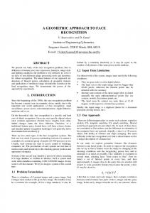
side surface ground plane support points Figure 1: Parts of a bed
implement functional constraints, but they are attached to declarative frames, which structure the constraints and schedule procedure activation based on the system’s current knowledge.1 Thus, a single model can be applied to different tasks. An example is the 3D Frame-based Object Recognition and Modeling system (3D FORM) [Walk88].
4
REPRESENTATION IN 3D FORM
Each 3D FORM model consists of three parts: a primitive geometric feature (where appropriate), a list of object parts (themselves 3D FORM models), and a set of geometric relationships among the primitive and parts that must be satisfied. The model is implemented as a network of frames where each object is represented by a single frame containing slots for primitive features, links to its parts (pointers to other frames), and specifications for its geometric relationships. Examples of models are called instances and are themselves frames. (See Figure 2). In particular, observed objects, when recognized, become instances of the appropriate model. 3D FORM also provides inheritance through a class hierarchy, as does Gruff-2. In the current implementation of 3D FORM, the primitive features are numeric ranges, points, lines and planes. Each primitive feature is represented as a frame, with slots to express its constraints. The slots of points, lines, and planes are designed so that each primitive can be specified in terms of lower primitives that it contains and/or higher primitives that it is contained in. For example, the slots of a line segment frame include points on the segment, its endpoints, its orientation vector, and normals of planes that it lies in. Empty slots are permitted in frame instances, and demons are provided to automatically compute slot values where appropriate. Structurally incomplete objects are simply represented using empty slots. Geometric relationships (also frames) are specified within the object definition. When a relationship is evaluated, the system ensures that the relationship is not inconsistent with the given arguments, and, if necessary, hypothesizes missing arguments that are consistent with the relationship. A perpendicularity relationship, for example, could verify the perpendicularity of two planar surfaces, or hypothesize one given the other. In this way, the reasoning performed by 3D FORM depends on current knowledge. The abilities of 3D FORM to represent structurally incomplete objects (including hypotheses), and to perform 1Technically, the models used by Gruff-2 are also frames, but do not make use of the declarative nature of slots, nor of demons (or message passing) to control behavior dynamically.
The sleeping surface is long enough and large enough to support the sleeper. range-geq comp-larger (value (DIAMETER SLEEPING-SURFACE)) comp-smaller (value (HEIGHT SLEEPER)) range-geq comp-larger (value (AREA SLEEPING-SURFACE)) comp-smaller (value (AREA SUPPORT-POLY SLEEPER)
The sleeping surface is parallel to the ground and has clearance above it. parallel-planes rel-pl1: (value (geom-feature SLEEPING-SURFACE)) rel-pl2: (value (geom-feature GROUND-SURFACE)) rel-dist: *king-bed-height* clearance clear-surface: (value SLEEPING-SURFACE) clear-extent: *king-bed-top-space* clear-obstacles: (value PARTS)
There is clearance to each side of the bed every SIDE-EDGES some SIDE-SURFACES perpendicular-planes rel-plane1: (value (geom-feature (SLEEPINGSURFACE))) rel-plane2: (value (geom-feature (SIDE-SURFACES)) rel-intline: (value (geom-feature (SIDE-EDGES))) every SIDE-SURFACES clearance clear-surface: (value SIDE-SURFACES) clear-extent: *king-bed-side-space* clear-obstacles: (value PARTS)
The support vertices are bottom-most relative to the normal to the ground plane, and they lie on the ground plane every SUPPORT-VERTICES every PART-VERTICES ordered-pts ordered-pt1: (value (geom-feature (SUPPORT-VERTICES)) ordered-pt2: (value (geom-feature (PART-VERTICES)) ordered-line: (value (norm (geom-feature (GROUNDSURFACE))) every SUPPORT-VERTICES points-on-plane onpl-pts: (value (geom-feature SUPPORT-VERTICES)) onpl-plane: (value (geom-feature GROUND-SURFACE)) onpl-dist: *support-tolerance*
The projection of the center of mass lies within the support convex hull (formed by the support vertices) convex-hull ch-vertices: (value (SUPPORT-VERTICES . all)) ch-polygon: (value (SUPPORT-CONVEX-HULL)) point-in-polygon pip-poly: (value SUPPORT-CONVEX-HULL) pip-point: (value CENTER-OF-MASS-PROJ) pip-tol: *support-polygon-tolerance* Figure 3: 3D FORM constraints for a bed
flexible knowledge-dependent reasoning make it particularly suitable for functional recognition.
5
FUNCTIONAL MODELS IN 3D FORM
This section describes the representation of a functional model using 3D FORM frames. Sections 5 and 6 will use the example of a bed (Figure 1).
The first requirement for representing a functional model is the ability to represent functional parts. In 3D FORM, parts are represented by frames attached to slots of the parent frame (Figure 2). These frames can represent single geometric primitives or grouped structures. Because the 3D FORM representation is hierarchical, each functional part can itself have subparts — frames that describe either functional or structural components. Examples include multiple non-adjacent planar faces grouped into a sleeping surface, and multiple support chains (themselves functional objects) grouped into a support structure. Hierarchical groupings effectively create a one-to-many relationship between functional and structural components. Because the representation is not entirely dependent on extracted features, object parts can be geometric constructions that are useful for reasoning, although not observable. For example, the side surfaces of a bed are not required for functionality; neither a hammock nor a platform bed has any. However, these surfaces are still useful to bound the side clearance polygons. contains a frame for the range [6,∞]. Alternatively, shape and size constraints can be expressed by relating quantities from one frame to another. This alternative is shown by the first two constraints in Figure 3, using the SLEEPER slot to represent the user of the bed. Relative pose constraints are imposed explicitly in the object model, either between parts of the object in question or between object parts and global objects, e.g. the ground plane. The relative pose of the sleeping surface of a bed and a fixed ground plane is expressed by the relationship template: (parallel-planes (rel-pl1 (value (geom-feature sleeping-surface)) (rel-pl2 ‘ground-plane) )
Support and clearance constraints also are imposed by relationship templates. The support relationship constrains the relative locations of the object’s support polygon and center of mass (computed slots in the object frame). A clearance relationship defines a volume of space relative to the object that must be empty, taking the complete set of object parts as one argument, and the required clear volume as the other. The complete set of relationship templates for the idealized bed frame is shown in Figure 3. Note the use of quantifiers “every” and “some” to apply constraints appropriately to multi-valued slots.
6
FUNCTIONAL RECOGNITION IN 3D FORM
In its most general form, the problem of functional recognition is a matching problem: given geometric information derived from an object’s image and one or more functional models, determine correspondences between scene geometry and the functional models. This definition subsumes several types of questions, such as “Where is the bed in the image?”, “Is the object a (better) bed or a chair?”, and “Why is the object not a bed?”. Depending on the input image(s), the data could be a complete or partial three-dimensional object description. The basic step in 3D FORM functional recognition is to apply a functional model to a generic object. In [Walk89], this process, called specialization, is described in detail. First, an object frame is created to represent geometric information from the image, including structural relationships among object parts. Next, the frame is defined as the functional type (BED) and an assignment of
Figure 7: Bed (top view) with two known legs (solid circles) and hypothesized third leg (open circle must lie in shaded region).
Figure 4: Bed scene
P-2
sleeper P-0 P-3
P-4 P-1
GND-0
Figure 5: Labeled range image of bed scene (object1 (instance 3d-object) (parts P-0 P-1 P-2 P-3 P-4) )
(object1 (instance bed) (parts P-0 P-1 P-2 P-3 P-4) (sleeping-surface P-0) (side-surfaces P-1 P-2 P-3) (side-edges edge29 edge28 edge27))
Figure 6: Object frame before and after specialization
object parts to functional parts is made. This assignment must satisfy all constraints in the object. Finally, the relationships of the new object are evaluated, including hypothesizing missing parts. Parts that are irrelevant to the object’s function are not used in specialized slots Parts that prevent functionality cause constraints to fail. Parts that work together to serve a function are grouped together as recursive subparts of the object. As an example, consider the scene in Figure 4. A doll (the sleeper) is standing next to a bed, which is to be recognized. This scene was imaged by a GRF-1 range finder, then, using a very simple implementation of plane extraction by region-growing, several planar surfaces from the bed (P-0 through P-5) were extracted, as well as a large portion of the ground plane (GND-0) The range image with bounded polygons and labels is shown in Figure 5.
For this simple case, the ground plane was assigned to extracted plane GND-0. This assignment is based on the fact that the orientation of the range sensor in the world is roughly known. A 3D-OBJECT frame was created with all other surfaces as its parts (Figure 6a). Next, the plane was specialized to BED. By type-checking, any of the faces was viable for the SLEEPING-SURFACE. However, surface P-0 was chosen because it is the only surface parallel to the ground plane. Note that the correct surface was chosen even though the segmentation was extremely crude. Once P-0 was assigned as the SLEEPING-SURFACE, surfaces perpendicular to it became potential SIDESURFACES. Since P-4 lies in a plane close to that of P-1, they are grouped together to form a composite side-surface (replacing the old P-1). In reality, only the P-1 surface should be labeled as a side-surface. Although the headboard and footboard of the bed impede access to the sleeping surface, both P-3 and P2 are labeled side-surfaces, because as the boundary between two separate clearance polygons, they violate neither. A more sophisticated access functional-object (see Section 7) would address this problem. Each intersection a side-surface with the sleeping-surface was computed as a SIDE-EDGE of the bed. The result is shown in Figure 6b. The side-edges of the bed are examples of hypotheses for parts that were not previously specified in the data. In a closed-loop system, computed parts such as these can be fed back to the lower-level segmentation process to update the segmentation. When no hypotheses are generated, the evaluation result corresponds to a functional or non-functional result, using the language of [Star93]. The equivalent of a possibly functional result includes hypotheses for the unknown information. An interesting example is shown in Figure 7, where a third leg is hypothesized to stabilize a surface supported by two visible legs.2 This hypothesis is generated by geometric reasoning within the support relationship frame, resulting in an (incomplete) object specification for the missing point. This hypothesis would be a reasonable answer to the question “What would be needed for this object to be a bed?” which no existing functional recognition system can do.
7
GENERALIZING FUNCTIONAL MODELS
The bed frame used as an example so far can be considered an “ideal bed”; it describes a standard piece of furniture but not everything that can be slept upon. To generalize this definition, one must consider that constraints can be satisfied to some degree, and the degree of satisfaction of all the constraints determines the desirability of the particular object as a bed. This section presents 2Although any chain of support from an appropriate support point to the sleeping-surface would satisfy the constraint, the simplest hypothesis (a vertical leg) is assumed as a heuristic.
examples of relaxing the constraints of a bed and suggests how they could be implemented within the 3D FORM framework. With regard to the sleeping surface, the shape constraint can be relaxed to allow shorter beds (e.g. a sofa used as a bed), or to allow multiple surfaces to be grouped into a sleeping surface (e.g. two chairs pushed together). The relaxed constraint could be expressed in terms of the degree to which the surface can support a reclining sleeper, and can be enforced or measured using the area of the support polygon(s) for the best hypothesized position of the sleeper on the sleeping surface. The area constraint in Figure 1 is an approximation to this constraint, assuming a polyhedral approximation to the sleeper in the reclining position, and using the support polygon relative to the sleeping surface (which would be further defined inside the sleeper frame). The orientation constraint for the sleeping surface can be relaxed to be mostly horizontal to allow a hammock or a reclining chair to be included. Again, with better geometric primitives to model the sleeper as an articulated object with comfort ranges for the articulations, the orientation constraint could be relaxed even further to measure the comfort of the articulated sleeper when placed in the best hypothesized position on the sleeping surface. Similarly, the constraint on the height of the sleeping surface and clearance to the side of the sleeping surface exist to ensure that the sleeper can get in and out of the bed. These constraints can be relaxed (with appropriate penalties to functionality) to allow beds that are too low (e.g. a sleeping bag or air mattress) or beds that are too high (e.g. the top bunk) provided that access is provided in some other way (e.g. a ladder). This constraint would be implemented as an additional slot of the bed frame to be filled with a new type of functional object (access-provider). This slot would be optional in general, but required in a bunk bed. To implement these generalizations, the requirement that the object meet all constraints to be recognized should also be relaxed. Instead of a functional / non-functional result, each computation would return a fuzzy measure of the degree to which each constraint is met (as in [Star94]) and these values would be combined into an overall measure of functionality. These measures of functionality would be useful in automatically deciding how to use each object and/or which object(s) to use for a given purpose.
8
CONCLUSION
This paper described some of the issues in developing functional models for object recognition, and also a framebased system for representing such models. The framebased system can recognize objects using functional models and complete data, and can also hypothesize what is missing when applying functional models to incomplete data. Recognition and functional part labeling of a simple bed object was demonstrated, and extensions to the basic model were described that can model a wide range of objects that can function as beds. I gratefully acknowledge Roddy Collins and Wendy Abbott for their help in preparing the recognition example for this paper.
References DiMa89 DiManzo, M., Trucco, E., Giunchiglia, F., and Ricci, F. FUR: Understanding Functional Reasoning. International Journal of Intelligent Systems 4, 1989, pp. 431-457. Fike85 Fikes, R., and Kehler, T. The Role of Framebased Representation in Reasoning. Communications of the ACM , 28, 3, Sept. 1985, pp. 904-920. Grim90 Grimson, W.E.L, Object Recognition by Computer: The Role of Geometric Constraints, MIT Press, 1990. Mann94 Mann, R. and Jepson, A. ‘Support’ in Support of Vision, IEEE Computer Society Workshop on the Role of Functionality in Object Recognition, June 1994. Moha92 R. Mohan and R. Nevatia, Perceptual Organization for Scene Segmentation and Description, IEEE Transactions on PAMI, 1 4 , 1992, pp. 616-635. Mulg92 Mulgaonkar, P.G., Cowan, C.K., and DeCurtins, J. Understanding Object Configurations Using Range Images. IEEE Transactions on PAMI 14, 2 , Feb. 1992, pp. 303-307. Requ80 Requicha, A.A.G. Representations of Rigid Solids. ACM Computing Surveys 1 2 , 4, Dec. 1980, pp. 437-464. Rivl94 Rivlin, E., Dickinson, S. and Rosenfeld, A., Recognition by Functional Parts, Technical Report CAR-TR-703, Center for Automation Research, University of Maryland, Feb. 1994. Sand90 Sanderson, A.C., de MeI llo, L.S.H., and Zhang, H. Assembly Sequence Planning. AI Magazine 11, 1, Spring,1990, pp. 62-81. Star93 Stark, L., Hoover, A.W., Goldgof, D.B. and Bowyer, K.W., Function-based object recognition from incomplete knowledge of object shape. IEEE Workshop on Qualitative Vision, June 1993. Star94 Stark, L. and Bowyer, K. Function-Based Generic Recognition for Multiple Object Categories. CVGIP: Image Understanding 59, 1, Jan. 1994, pp. 1-21. Thad94 Thadani, S., Constructing Functional Models of a Device from its Structural Description, Ph.D. Thesis, Department of Computer and Information Science, Ohio State University, 1994. Walk88 Walker, E.L., Herman, M., and Kanade, T. A Framework for Representing and Reasoning about Three-dimensional Objects for Vision. AI Magazine 9, 2, Summer 1988, pp. 47-58. Walk89 Walker, E.L., Frame-Based Geometric Reasoning for Construction and Maintenance of 3D World Models, Ph.D. Thesis, School of Computer Science, Carnegie Mellon University, 1989.