A Graph-Based Formalism for RBAC MANUEL KOCH Freie Universitat ¨ Berlin and LUIGI V. MANCINI and FRANCESCO PARISI-PRESICCE Universita´ di Roma La Sapienza
Role-Based Access Control (RBAC) is supported directly or in a closely related form, by a number of products. This article presents a formalization of RBAC using graph transformations that is a graphical specification technique based on a generalization of classical string grammars to nonlinear structures. The proposed formalization provides an intuitive description for the manipulation of graph structures as they occur in information systems access control and a precise specification of static and dynamic consistency conditions on graphs and graph transformations. The formalism captures the RBAC models published in the literature, and also allows a uniform treatment of user roles and administrative roles, and a detailed analysis of the decentralization of administrative roles. Categories and Subject Descriptors: D.4.6 [Operating Systems]: Security and Protection— Access Controls; K.6.5 [Management of Computing and Information Systems]: Security and Protection General Terms: Design, Management, Security Additional Key Words and Phrases: Access control in information systems, correctness, decentralized administration, graph transformations, permission management, role-based access control
1. INTRODUCTION The activities within a computer system can be viewed as a sequence of operations on objects. One of the primary purposes of security mechanisms is access This research was partially supported by the European Community under TMR Network GETGRATS, Esprit Working Group APPLIGRAPH and by the Italian MURST. Some of the results in this article, in a preliminary version, have appeared in KOCH, M. MANCINI, L. V., AND PARISI-PRESICCE, F. 2000. A formal model for role-based access control using graph transformation. In Proceedings of the 6th European Symposium on Research in Computer Security (ESORICS 2000), F. Cuppens et al., eds. Lecture Notes in Computer Science, vol. 1895. SpringerVerlag, New York, pp. 122–139. ¨ Informatik, FU Berlin, Takustr. 9, 14195 Berlin, Authors’ addresses: M. Koch, Institut fur Germany; email:
[email protected]; L. V. Mancini and F. Parisi-Presicce, Dipartimento di Informatica, Universita´ di Roma La Sapienza, Via Salaria 113, 00198 Roma, Italy; email: {lv.mancini,parisi}@dsi.uniromal.it. Permission to make digital or hard copies of part or all of this work for personal or classroom use is granted without fee provided that copies are not made or distributed for profit or direct commercial advantage and that copies show this notice on the first page or initial screen of a display along with the full citation. Copyrights for components of this worked owned by others than ACM must be honored. Abstracting with credit is permitted. To copy otherwise, to republish, to post on servers, to redistribute to lists, or to use any component of this work in other works requires prior specific permission and/or a fee. Permissions may be requested from Publications Dept., ACM, Inc., 1515 Broadway, New York, NY 10036 USA, fax +1 (212) 869-0481, or
[email protected]. ° C 2002 ACM 1094-9224/02/0800–0332 $5.00 ACM Transactions on Information and System Security, Vol. 5, No. 3, August 2002, Pages 332–365.
A Graph-Based Formalism for RBAC
•
333
control (AC), which consists of determining and enforcing which active entities, such as processes, can have access to which objects and in which access mode. This article focuses on Role-Based Access Control (RBAC), an AC mechanism described in [Sandhu et al. 1996; 1999; Osborn et al. 2000]. It appears that RBAC tries to match the need of many organizations to base AC decisions on the roles assigned to users as part of the organization. In this context, RBAC facilitates the administration of AC decisions while making the process less error-prone. A formal analysis of RBAC would be useful for the following reasons: (1) Prove the properties of a given RBAC specification. RBAC consists of a family of conceptual models and the most advanced ones include role hierarchies, constraints, and decentralized administration of roles; this complexity requires a formal setting to ensure that a RBAC specification meets basic correctness properties of the system. (2) Compare different AC models. For example, to better meet the needs of a specific application, one may want to choose among discretionary AC, mandatory AC and RBAC; to this extent one could compare their advantages and disadvantages also using the respective type graphs, which is a mechanism to constrain the form of the graphs that represent acceptable system states. (3) Predict the system behavior in combining different AC policies. For example, to support the evolution of a policy, due to changing requirements [Koch et al. 2001a] and role transition, that is the means for moving towards RBAC in coexistence with previous models of AC. This article presents a formalization of RBAC using graph transformations that is a graphical specification technique based on a generalization of classical string grammars [Rozenberg 1997] to nonlinear structures. The advantages of using the graph transformation formalism are: —an intuitive visual description of the manipulation of graph structures as they occur in the AC; —an expressive specification language, which allows, for example, the detailed specification of various schema for decentralizing administrative roles; —a specification of static and dynamic consistency conditions on graphs and graph transformations; —a uniform treatment of user roles and administrative roles; —an executable specification that exploits existing tools [Ehrig et al. 1999] to verify the properties of a given graph-based RBAC description. The issues addressed in this article include: the presentation of a formal framework for RBAC which allows the specification and verification of consistency requirements; the administration of permission-role assignment and revocation, discussed in Nyanchama and Osborn [1999] for the case of one administrator; the discussion of some complex operations, such as the revocation cascade of users membership when administrative roles are decentralized, and a comparison of several possible solutions. The comparison of different AC policies within the graph grammar formalism and the analysis of the system ACM Transactions on Information and System Security, Vol. 5, No. 3, August 2002.
334
•
M. Koch et al.
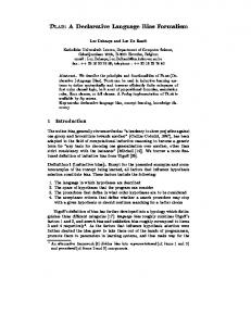
Fig. 1. The type graph for the RBAC model.
behavior in combining different AC policies are the subject of another paper [Koch et al. 2001]. The rest of this article is organized as follows: Section 2 overviews the basic notions of graph transformations. Section 3 describes the graph based modeling of a RBAC model with one administrator. Section 4 introduces permissions into the graph model by specifying the role-permission assignment proposed in Nyanchama and Osborn [1994, 1999]. Section 5 shows how to prove the graph based correctness of a RBAC specification and presents the algorithm for constructing consistent graph rules. In Section 6, we describe a graph model for decentralized RBAC. In Section 7, we show that the formalism is sufficiently expressive to describe alternative solutions to some nontrivial issues mentioned in Sandhu [1998], such as the revocation of assignment in a decentralized administration of roles. The specification of the proposed different alternatives are compared in Section 8. Section 9 contains some concluding remarks and additional comparison with existing work. 2. GRAPH TRANSFORMATION A graph consists of a set of nodes and a set of edges. Edges are directed, that is, they run from a node (the source of the edge) to a node (the target of the edge). Each node and each edge has a type. The available node types and edge types are specified in a type graph, where each of its nodes represents a node type and each of its edges represents an edge type. Figure 1 shows the type graph used to describe the role-based access control models introduced later. It provides the node types u, s, r and ar. Nodes of type u represent users, nodes of type r are roles, nodes of type ar are administrative roles and nodes of type s model sessions. An edge between a session node s and a user node u represents the ownership of the session s by the user u; an edge from a user node u to a role node r the membership of u to r; an edge from a user node u to an administrative role ar the membership of u to ar; an edge from an administrative role ar to a role r the responsibility of ar for r; an edge between a session node s and a role r the activation of r in s; loops at nodes ar and r are used to model the administrative and role hierarchy, respectively. A type graph is a pattern for a whole class of graphs. A graph G belongs to this class if one can find for each node and edge in G the corresponding node and edge type in the type graph. A type graph represents a constraint and the membership of a graph to the class defined by the type graph corresponds to the graph satisfying the constraint. Notice that a type graph represents negative constraints as well. For instance, in any graph ACM Transactions on Information and System Security, Vol. 5, No. 3, August 2002.
A Graph-Based Formalism for RBAC
•
335
Fig. 2. A RBAC state graph.
belonging to the class of the type graph in Figure 1 there can be no edge between two different sessions. Figure 2 depicts a graph satisfying the constraints expressed in the type graph in Figure 1. Several nodes of the same type may occur in one graph and unique labels are used to distinguish them. The labels of the nodes are u1, u2, r1, r2, r3, s1, s2, ar1. Intuitively, user u2 of type u is assigned to role r3 of type r with sessions s1 and s2 of type s, and administrative role ar1 of type ar is responsible for role r1. User u1 of type u is not assigned to any role. From now on, to simplify the graph rule, administrators assigned to administrative roles are not shown. This section focuses on the main components of graph transformation, which are a transformation rule and a transformation step. We briefly introduce the main concepts in this section. A detailed (also formal) introduction can be found in the handbook to graph transformation [Rozenberg 1997]. A graph represents a state of a system, for example a security system based on roles as shown in Figure 2. State changes are specified by graph transformation rules, called just rules in the sequel. A rule is formally given by a graph morphism r : L → R, where both L and R are graphs, called left-hand side and right-hand side, respectively. A graph morphism r : L → R consists of an injective partial mapping rn between the sets of nodes and an injective partial mapping re between the sets of edges of L and R. The mappings must be compatible with the graph structure, the types and the labels of nodes. Compatible with the graph structure means that whenever the mapping for edges is defined for an edge e, the mapping for nodes is defined for the source s and the target t of the edge e and rn (s) and rn (t) are the source and target nodes of the edge re (e) in the right-hand side. Compatible with the type (respectively, label) means that nodes are mapped only to nodes of the same type (respectively, label). If the mappings are total, we call the graph morphism total. The graph L describes which objects a graph G must contain for the rule r : L → R to be applicable to G. Nodes and edges of L for which the partial mappings are undefined are intended to be deleted by the rule. Nodes and edges of L for which the partial mappings are defined are intended to be preserved and have an image in R. Nodes and edges of R without a preimage in L are newly created. Note that the actual deletions/additions are performed on the graphs to which the rule is applied. Complete sets of rules for different RBAC models are given in Sections 3, 4, 6 and 7. ACM Transactions on Information and System Security, Vol. 5, No. 3, August 2002.
336
•
M. Koch et al.
Fig. 3. Rules add to role and remove user.
We explain the notion of a rule and its application to a graph by means of the examples in Figure 3. The first rule is add to role. Its intended meaning is to make a user a member of a role. The membership of a user to a role is modeled by an edge that this rule must create, from the u to the r node. The assignment of a user to a role takes place by an administrative role that is responsible for the role. In our graph model, responsibility is indicated by an edge from the ar to the r node. So, the left-hand side L consists of one node of type ar, one of type r and one of type u, and an edge between the ar node and the r node to show the responsibility. The left-hand side of the rule add to role contains additionally a dashed edge between the u and the r node. This dashed edge represents a negative application condition. A negative application condition for a rule r : L → R is a pair (L, N ), where the graph L is a subgraph of N . The graph N represents a structure that, as a whole, must not occur in G for the application of the rule. In the following notation for rules, we depict the pair (L, N ) only by the graph N , where the subgraph L is drawn solid and the parts N \L are drawn by dashed lines. For the rule add to role, the graph L consists of the nodes u, r and ar as well as the edge between the ar and the r node. The graph N contains additionally the edge between the user node u and the role node r. A graph G satisfies a rule r : L → R with a negative application condition (L, N ) if L occurs in G and it is not possible to extend L to N . If the extension of L to N is possible, then the unwanted structure occurs and the negative application condition is not satisfied. Note that the presence of only a part of the unwanted structure N \L is acceptable: for example in the rule veto deletion in Figure 25, there could be a senior role, provided that it is not assigned to the user. For the rule add to role, a membership edge between the u and r nodes must not exist in G before the rule application. The nodes of the rule add to role do not carry labels. This representation for a rule is intended as a pattern for a whole set of rules: each of them is obtained with a specific choice of labels. For example, if we want to specify that the administrative role CSO assigns the user Bob to the role manager, then the ACM Transactions on Information and System Security, Vol. 5, No. 3, August 2002.
A Graph-Based Formalism for RBAC
•
337
actual parameters (the node labels CSO, Bob, manager) must be supplied for the formal parameters when the pattern rule add to role is invoked. The graph transformation tool then uses appropriate data structures to perform efficiently the application of the pattern rules, and to avoid the exhaustive search of all possible matches of the pattern rules in the graph. Whereas add to role is a preserving rule (the graph morphism for the rule is total, so that the rule does not delete anything), the rule remove user (see Figure 3) removes a user from the system. Since we do not want to have active sessions that do not belong to any user, also all the sessions of the deleted user must be closed, that is, deleted from the system graph. Therefore, the left-hand side of remove user consists of a user node u connected to a session node s. The double circle around the s node (these nodes are called set nodes) specifies that the rule has to be applied to all session nodes s connected to the user; this means, in particular, that the rule can be applied also to users without active sessions. Rules with set nodes are a schema for a set of rules: for each n ≥ 0 there is a rule in which the (set) node occurs exactly n times. Alternatively, a rule with set nodes could represent a rule expression [Große-Rhode et al. 2000]. The right-hand side of rule remove user is empty to specify the deletion of the user with all her/his sessions. The application of a rule r : L → R (a pattern with actual parameters) to a graph G takes place in four steps: (1) Find the left-hand side L as a subgraph in G. The subgraph is denoted by L(G). (2) If every negative application condition (L, N ) is satisfied (that is, L(G) cannot be extended in G to N ), then: (a) Remove all nodes and edges from L(G) that are not present in R. (b) Add all nodes and edges in R that are not present in L. The nodes occurring both in L and in R (if any) are used to connect the new parts to the old ones to obtain the new graph H. The top of Figure 4 shows an instance of the rule add to role. The label for the u node is u1, the label for r is r1 and the label for ar is ar1. Assuming that users, roles and administrative roles have unique labels, the left-hand side L of the instance rule may occur at most once in a graph. Considering the graph of Figure 2, the left-hand side L of the given instance rule add to role occurs in it. The only possible matching is indicated in Figure 4 by the gray nodes. Next, we have to check the negative application condition of the rule that forbids an edge between the u1 and the r1 nodes. Since the edge does not exist for the given matching, the condition is satisfied and the rule is applied. It deletes nothing and inserts the edge between the nodes u1 and r1. The transformed graph contains a new edge indicating that the user u1 is a member of the role r1. We now apply the rule remove user with user node labeled u2 to this new graph. User node u2 appears in the graph H of Figure 5, and the only possible matching of rule remove user is shown by the gray nodes. Since user u2 has two sessions, they also have to be removed. The double circle in the rule remove user requires that we match all the sessions of the user, and not just some of ACM Transactions on Information and System Security, Vol. 5, No. 3, August 2002.
338
•
M. Koch et al.
Fig. 4. Application of rule add to role.
Fig. 5. Application of rule remove user.
them. A set node has an empty label that can match any label in a graph. If there are no session nodes in the state graph, the rule remove user is still applicable. In Figure 5, the set node s is matched with the session nodes s1 and s2. There is no negative application condition to check. We delete the whole gray part, since there are no edges in the right-hand side of remove user. Notice that the deletion of the session node s2 leaves a dangling edge, that is, an edge without a source node. The same is true for the edge between the user u2 and the role r3. Since dangling edges are not allowed by the definition of graphs, dangling edges are automatically deleted by definition of graph transformations (single pushout approach in Rozenberg [1997]). ACM Transactions on Information and System Security, Vol. 5, No. 3, August 2002.
A Graph-Based Formalism for RBAC
•
339
Fig. 6. Example of a role hierarchy graph.
For simplicity, in all the examples in the remainder of the paper, rules are indicated by their patterns. Instance rules with specific labels are used if needed. In Section 3, the concept of a path is used. A path in a graph is a sequence of edges, where the target node of each edge in the sequence coincides with the source node of its successor edge in the sequence. We denote paths between two nodes by an edge equipped by a “∗” for paths of arbitrary length including length 0 or a “+” for paths that have at least length 1 (see, e.g., the rules in Figure 7). Graph transformations are supported by several tools described in Ehrig et al. [1999]. They provide mainly graphical editors to insert/draw the graphs, to specify rules with negative application conditions and a graph transformation engine to apply rules. The selection of the particular rule is determined by the designer of the specification who is using the actual graph transformation tool.
3. ROLE-BASED ACCESS CONTROL This section gives an initial description of the use of graph transformations to specify a particular RBAC model. The RBAC model considered in this section has a role hierarchy and focuses on the role-user assignment. Different choices of rules can be used to describe alternative RBAC definition in the literature. An example of a role hierarchy graph is shown in Figure 6, where roles are given by nodes of types r and edges between roles show the inheritance (or dominance) relation. For example, the edge pointing from the role Chief Manager to the role Senior Manager represents the dominance of the role Chief Manager over the role Senior Manager, in the sense that the Chief Manager has all the permissions of the Senior Manager and each user authorized for the role Chief Manager is authorized for the role Senior Manager as well. Using this direction for edges, the implicit authorization of a user for a role can be easily expressed by directed paths through the graph from the user node to the role node. For example, a user in the role Chief Manager is implicitly authorized ACM Transactions on Information and System Security, Vol. 5, No. 3, August 2002.
340
•
M. Koch et al.
Fig. 7. Graph rules for the centralized RBAC model.
for the roles Senior Manager and Junior Manager, since there is a path from the Chief Manager role node to the role nodes for Senior Manager and Junior Manager. It would also be possible to model relationships between roles with edges in the opposite direction (i.e., the edge would point from Senior Manager to Chief Manager). This approach emphasizes the subset relation on sets of permissions and does not have the ability to express implicit authorizations simply as directed paths from user to permissions as possible, (e.g., in Figure 8). Since we consider a centralized RBAC model in this section, there is only one administrative role responsible for any role in the role graph and therefore an administrative role hierarchy graph is not necessary. Graphs for administrative role hierarchies are relevant in Section 6, where we propose different alternatives. A user can be assigned to or revoked from a role. A user is a member of a role if she/he is directly assigned to a role. She/he is authorized for a role, if the role is inherited from a role to which the user is assigned. A user can establish a session during which the user activates a subset of the roles of which she/he is a member. Note that the concept of sessions corresponds to the notion of subjects in the classical AC terminology. The creation and deletion of roles are considered in Section 6; for simplicity here we consider only the following operations: add user, remove user, add session, remove session, add assignment, remove assignment, activate role and deactivate role. All these operations are now modeled by the graph transformation rules in Figure 7. add user and remove user: The rule add user has an empty left-hand side, since users can be created at any time. The result of the rule is a new user represented by a node of type u. The rule remove user removes a user by deleting the corresponding user node u. To ensure that there are no active sessions of this user after the deletion of the user, all his/her sessions are deleted as well. This is indicated by the double circled session node in the left-hand side of rule remove user. The interpretation is that all sessions connected to the user are ACM Transactions on Information and System Security, Vol. 5, No. 3, August 2002.
A Graph-Based Formalism for RBAC
•
341
deleted. The deletion of the session implies the deletion of all the connections to roles that the session has (guaranteed by the graph transformation approach). The roles themselves remain. add session and remove session: A session is graphically presented by a node of type s. It always has a connection to one user. The rules for the creation and deletion of sessions are new session and remove session. A session node s is immediately connected by an edge to the user who is using s. A session can be deleted at any time regardless of the presence of active roles of the session. The session is deleted by removing the session node. This implies that all the session-to-role edges are deleted as well, automatically. add assignment and remove assignment: The assignment of users to roles is modeled by the rule add to role, which connects with an edge, called assignment edge, the user node and the role node. The user becomes a member of this role, only if he/she is not already authorized for the role r and is not a member of a role that inherits r. The first requirement is specified by the upper negative application condition, that forbids the presence of an assignment of the user u to a higher role having a path to role r. Since the edge carries a “∗”, the path could also be empty, forbidding the assignment to a role of which the user is already a member. The lower application condition forbids a path from the role r to an inheriting role of which the user is already a member. This requirement ensures that, at the same time, a user can be a member only of independent roles, that is, roles without a path in the role hierarchy graph. An arbitrary user-to-role assignment can be reduced to an equivalent one satisfying this property, only equivalent from the point of view of the permissions granted to each user. The rule remove from role removes a user u from a role r by deleting the assignment edge between them. The deletion of the assignment edge between u and r removes the authorization of the user u for this role r and all roles that inherit from r, since there cannot exist a role, to which the user belongs, either higher or lower in the hierarchy (ensured by rule add to role). If a user loses the authorization for a role r, all the sessions of the user must deactivate the role r. Therefore, all the sessions of the user must be disconnected from all the roles that inherit from r (if the independent role assumption is removed by giving an alternate semantics to rule add to role, the effect of removing from a role will be different). activate role and deactivate role: A user can activate any role r for which she/he is authorized. A user is authorized for r if there is a path starting with an assignment edge and ending in r. The corresponding graph rule is activate role. An edge between the session node and the role node shows that the role is active in the session. This edge is created by the user of the session. The symbol “∗” on the edge between the roles indicates a (possibly empty) path through the role hierarchy. An empty path indicates that a user can also activate a role she/he is directly assigned to. Role r can only join a session if r is not already a member of that session, as indicated by the dashed edge between the session node and the role node. This rule allows the activation of a role even if a senior role is already active. We can model a semantics where a role r 0 can be activated only if that role and all its seniors are not already active. To this extent, the ACM Transactions on Information and System Security, Vol. 5, No. 3, August 2002.
342
•
M. Koch et al.
Fig. 8. A graphical specification of user-role, role-permission and permission-object assignment.
left-hand side of the rule activate role would have one more role node r 0 connected by a path edge to the existing lower role, and in the right hand side, the session node would be connected to this new role node r 0 . The deactivation of a role from a session is specified by deleting the edge between the session and the role node. 4. INTRODUCING PERMISSIONS This section deals with permissions and their assignment to roles. We use the role-permission assignment model proposed in Nyanchama and Osborn [1994, 1999] throughout this section to show the specification of (one possible) rolepermission assignment by graph transformations. Nyanchama and Osborn consider permissions1 as a pair consisting of an object and the set of its access modes. A role is then defined by a name and a set of permissions. In our graph model, permissions are modeled by nodes of type p possibly connected to several objects. Each edge between a permission and an object node models a permission pair according to Nyanchama and Osborn [1999], where the p node is the access mode. The role-permission assignment is modeled by edges connecting role nodes with permission nodes. Our graph model is similar to Baldwin’s [1990] privilege graphs (PG). A PG is a three-layered acyclic graph (see Figure 8), where the first layer represents the users, the second one the roles and the third one the permissions consisting of edges from permission nodes to objects. According to Baldwin, the third layer represents the functionalities in the PG. Edges from users to roles model the user-role assignment and edges from roles to permissions the role-permission assignment. The graph in Figure 8 shows the user–role assignment (as introduced in the previous section), the role–permission assignment and the permission– object assignment. The permission nodes p in this example are read, write and execute, but in general they can be more complex access modes. Objects are containers of information, such as files or directories in an operating system. The authorization of a user u for an object o is given by the existence of a path 1 We
use the term “permission” following Sandhu [1998] instead of the term “privilege” used in Nyanchama and Osborn [1999].
ACM Transactions on Information and System Security, Vol. 5, No. 3, August 2002.
A Graph-Based Formalism for RBAC
•
343
from u to o. This requires the user to be in a role that has the permission to access the object. Bob as Project Leader has execute right on object o4. Whereas the role graph in the previous section is not restricted to any structure, Nyanchama and Osborn organize roles in a special graph model aiming at reducing the complexity of permission management in a role-based security system. Their role graph is acyclic and has a unique minimal role and a unique maximal role: the maximal role has the maximal set of permissions, the minimal role the minimal set of permissions (possibly the empty set). There is a path from each role of the role graph to the minimal role and there is a path from the maximal role to any other role of the role graph. Inheritance of permissions “flows” against the direction of edges (in contrast to inheritance of the user-role relationship), that is, if there is an edge rs → r j in the role graph then the senior role rs inherits all the permissions of the junior role r j . A permission is a direct permission for a role if the permission is directly assigned to the role by an edge. A permission is in the set of effective permissions of a role if the role has this permission directly or by inheritance. Therefore, by inheritance, each role has the permissions of the minimal role, and the maximal role has the permissions of all the roles in the role graph. Nyanchama and Osborn organize the roles in a role graph to avoid redundancy, in the sense that, whenever a role has a direct permission, the same permission must not be assigned directly to any of its senior roles. This is motivated by the fact that, by inheritance, the senior role has all the permissions of its junior roles. Furthermore, the role graph must be transitive reduced [Aho et al. 1972], that is, there are no edges ri → r j whenever there is a path ri →+r j in the graph. Operations for role-permission assignment in Nyanchama and Osborn [1999] include the addition, deletion and partition of roles. These operations must preserve the structure of the role graph and, in particular, they must not create redundancies with respect to role-permission assignment. 4.1 The Graph Model for Role-Permission Management This section introduces the graph model for role-permission assignment similar to the one shown in Nyanchama and Osborn [1999], while several roles with the same set of permissions are not allowed there, this is possible in our model. Each operation for role management in Nyanchama and Osborn [1999] is considered a transaction: an operation starts in a consistent state and must end in a consistent state. If, during the operation, an inconsistent state is produced, for example, having two roles with the same set of permissions, the operation is aborted, leaving the role-permission assignment unmodified. Our proposed graph model does not have this transactional viewpoint: the insertion of roles is specified by the two rules in Figure 9. First, a role without direct permissions is added, second, the direct permissions are incrementally inserted. During this incremental process, a role can be generated with the same permissions as those of another role. We have to mention, however, that a transaction concept can be introduced also in the graph model by using rule expressions [Große-Rhode et al. 2000]. For simplicity, however, we decided to have a slightly ACM Transactions on Information and System Security, Vol. 5, No. 3, August 2002.
344
•
M. Koch et al.
Fig. 9. Graph rules for role/permission management: role insertion.
different model from the one in Nyanchama and Osborn [1999] rather than to complicate the graph model by introducing rule expressions. The graph rule insert role in Figure 9 adds a new role r to the role graph. Its left-hand side contains a set of senior roles rs and a set of junior roles r j between which the role r is going to be inserted. Since Nyanchama and Osborn [1999] always requires a maximal and minimal role in the hierarchy graph, there always exists at least one senior and at least one junior role. To maintain a transitively reduced role graph, all direct edges from senior roles rs to junior roles r j must be deleted. The new inserted role r has no direct permissions, but, by inheritance, it has all the permissions of the juniors. In particular, if there exists only one junior role, the new role and the junior role have initially the same permissions. The inserted role r is a common-senior [Nyanchama and Osborn 1999] of the junior roles, that is, the union of the effective permissions of the junior roles is a subset (in our case the same set) of the effective permissions of the common senior role. We remind the reader that this rule, as well as all the following ones, are rule patterns as explained in Section 2. The assignment of permissions to roles is modeled by the graph rule add direct permission. A permission must not be assigned to a role r if the permission is a direct permission of one of r’s juniors. This is specified by the negative application condition. The direct assignment of a permission p to a role r influences all of r’s senior roles as well. To avoid redundancy, the direct assignment of permission p has to be removed from all the senior roles. This is specified by the set node at the top of the left-hand side of the rule. The set node says that for all rs seniors of the role r which have a direct assignment by an edge e to the permission node p, the edge e has to be moved down to role r. If none of the senior roles has a direct assignment to p, the rule is still applicable and the direct assignment edge between r and p is simply added (set nodes and incident edges are ignored if there are no nodes to be matched to). The deletion of roles removes a role from the role graph. In Nyanchama and Osborn [1999], two possibilities for the treatment of permissions are suggested, namely either permission elimination or permission distribution. Permission elimination requires the removal of the path associated with the deleted role. Permission distribution transfers the direct permissions of the deleted role to all the immediate senior roles. The graph rules in Figure 10 model both kinds of deletion. The rule delete role permission distribution removes the role from the role graph and the direct permission assignments are moved up to all immediate senior roles. In the case of permission elimination specified by rule delete role permission elimination, the assignment is simply deleted. ACM Transactions on Information and System Security, Vol. 5, No. 3, August 2002.
A Graph-Based Formalism for RBAC
•
345
Fig. 10. Graph rules for role/permission management: role deletion.
It is up to the administrator to decide which of the two rules is applied when a particular role is deleted. In both rules, the junior and senior roles are marked (gray for junior roles, black for senior roles) in order to distinguish them for the following connection, specified by the two rules connect and end connect. The rule connect takes one junior role r j and connects it to all the senior roles rs . Since a direct connection between a senior and the junior role is allowed only if there does not already exist an intermediate role connecting the senior with the junior, the rule connect has a negative application condition forbidding its application in the presence of an intermediate role. This ensures that only unrelated senior roles are connected directly with the junior. The junior role is turned white again, since all connections for this junior role are established after this rule application. On the other hand, the senior roles remain black since they could be necessary for other junior roles. When all the junior roles are treated, the senior markings can be turned to white by the rule end connect. The negative application condition ensures that there are no untreated (gray) junior roles. ACM Transactions on Information and System Security, Vol. 5, No. 3, August 2002.
346
•
M. Koch et al.
Fig. 11. Graph rules for role/permission management: vertical role splitting.
The remaining operation is that of role partition [Nyanchama and Osborn 1994]. A role can be partitioned either vertically or horizontally. Considering vertical splitting, a role r is split into an ordered set of roles x1 → x2 → · · · → xn . The direct permissions of r are disjointly distributed over the roles x1 · · · xn . This kind of splitting is modeled by the graph rule split vertically in Figure 11. A role r is substituted by a linearly connected path of roles. The dots between the new inserted roles indicate that the role can be split into an arbitrary number of connected roles. The new roles, as well as the direct permissions of the old role, are marked gray for the distribution of the permissions to the new roles, done by the rule distribute permission. This rule assigns one of the marked permissions to one of the marked roles. To ensure a disjoint distribution, the permission color is set to white afterwards. If all permissions are distributed, the color of the new roles is set to white by means of rule end split. The negative application condition of end split requires that there does not exist a gray p node any longer. Horizontal splitting is modeled by the graph rule split horizontally in Figure 12. Horizontal role partition splits a role into a set of independent roles, that is, not related among them. The new roles have the same seniors and juniors of the split role. The rule split horizontally substitutes a role node with an arbitrary number of new nonrelated role nodes. Each new role is connected to all the senior roles and all the junior roles of the split role. The direct permissions and the new roles are marked gray to distribute the permissions. The actual distribution takes place by the rule distribute permission. Unlike the distribution rule for the vertical splitting, a permission may be assigned to several roles. Therefore, the rule distribute permission in Figure 12 does not change the color of the permission node p to white, so that the rule may be applied again for the same permission: horizontal permission distribution is done non-disjointly as in Nyanchama and Osborn [1994]. To ensure that an edge is inserted at most once between a permission and a role, the negative application condition is added. If a permission is distributed to all the roles that shall possess this permission, its color can be changed back to white with rule end permission distribution. The rule end split is used again to complete the splitting. Note that specific permissions can be assigned to specific new roles by choosing the appropriate labels for the nodes of the rule patterns. ACM Transactions on Information and System Security, Vol. 5, No. 3, August 2002.
A Graph-Based Formalism for RBAC
•
347
Fig. 12. Graph rules for role/permission management: horizontal role splitting.
5. GRAPH-BASED CORRECTNESS OF RBAC We now show how the graphical formalism can be used to prove the correctness of a RBAC specification. We clarify the graphical concepts with a running example taken from Gavrila and Barkley [1998]. There, a set of properties is given that defines the consistency requirement for a RBAC database. A state of the RBAC database having these properties is called consistent. One property from this set is (1) ∀u ∈ U S E R S, ∀r1 , r2 ∈ R O LE S, r1 , r2 ∈ active rol es(u) ⇒ (r1 , r2 ) 6∈ d sd . The dynamic separation of duties (d sd ) is a relation on roles. Roles related by a d sd relation must not be active in the same session of a user at the same time. In Gavrila and Barkley [1998], the semantics of the basic operations of the RBAC model is specified using both set theory and additional logical conditions. It is also shown that a given RBAC specification is correct in the following sense: if the RBAC database is in a consistent state, then the database remains in a consistent state after the operation is performed. The specification of the activate role operation in Gavrila and Barkley [1998] (where it is called addActiveRoles) is reported below. Note that to prevent the operation activate role from violating the property (1) an additional logical condition must be used. addActiveRoles Arguments: user,roleset Semantics: active rol es0 = (active rol es \ {user 7→ active rol es(user)}) ∪ {user 7→ active rol es(user) ∪ rol eset} Conditions: user ∈ U S E R S rol eset ⊆ authorized rol es(user) ∀r1 , r2 ∈ (rol eset ∪ active rol es(user)), (r1 , r2 ) 6∈ d sd ACM Transactions on Information and System Security, Vol. 5, No. 3, August 2002.
348
•
M. Koch et al.
Fig. 13. Graphical constraint for dsd-relation (left) and rule activate role.
Hence, in Gavrila and Barkley [1998], the designer has to perform three steps: (1) define the consistency properties on the entire system, (2) derive from Step (1) the conditions for each operation, and (3) prove that the execution of each operation, satisfying the conditions in Step (2), preserves the consistency properties defined in Step (1). In contrast, in our approach the designer has to perform Step (1) only, that is, to define the consistency properties of the system. In Step (2), for each operation, the derivation of the conditions from the consistency properties can be performed automatically, following a theoretical construction proposed in Heckel and Wagner [1995]. The result of such an automatic construction is a set of graph rules that is guaranteed to satisfy the given consistency properties and therefore the complex proofs of Step (3) are not needed anymore. Our approach also presents some advantages when the consistency properties must be modified in a system already specified. In such a case, the designer can define a new consistency property and can use the automatic construction to change the existing rules for each operation to satisfy the new consistency properties. In Gavrila and Barkley [1998], such an incremental modification requires human intervention in each of the three steps described above. Consistency properties are specified by graphical constraints. A graphical constraint is a graph that represents a forbidden structure. A graph is consistent with respect to a graphical constraint, if this structure does not occur in the graph. The left side of Figure 13 shows the graphical constraint for the consistency property (1) above. The graphical constraint is given by a graph consisting of a session node having two active roles that are connected by a double-headed edge. This edge specifies the dsd-relation, that is, two roles are in the d sd -relation if there exist such a double-headed edge between them, otherwise they are not. The rule activate role in Figure 13 (see also Figure 7), applied without modification, could produce an inconsistent state by creating an edge between a session node and a role which is in dsd-relation to another role of the same session. Therefore, this rule has to be completed by adding a negative application condition which prevents the activation of incompatible roles. The negative application condition can be constructed automatically during the design phase. The algorithm in Figure 14 (with the procedures specified in Figure 15 in pseudo-code) describes the mechanical construction of the set of application conditions for a given rule and a given graphical constraint. The worst case complexity of the algorithm is exponential on the size of the graphical constraint gc and of the two graphs defining the rule r. ACM Transactions on Information and System Security, Vol. 5, No. 3, August 2002.
A Graph-Based Formalism for RBAC
•
349
Fig. 14. The algorithm for the construction of a consistent rule.
Fig. 15. The procedures used by the algorithm in Figure 14.
However, the complexity does not depend on the size of the state graph of the whole system. Both the graphical constraint gc and the rule r input to the algorithm are small graphs, typical examples are shown in Figure 7 and Figure 20. Furthermore, this algorithm is used only during the design of the policy (and subsequent modification) and not during the enforcement of the policy. We call the modified rule consistent with respect to the graphical constraint in the sense of the following theorem. ACM Transactions on Information and System Security, Vol. 5, No. 3, August 2002.
350
•
M. Koch et al.
Fig. 16. The gluings of the right-hand side of rule activate role and the graphical constraint.
THEOREM 1. Given a rule r, a graphical constraint gc, a graph G consistent with respect to gc, and the rule r(gc) modified by the algorithm in Figure 14 the graph H resulting from an application of r(gc) to G is consistent with respect to gc. The proof of the theorem is based on the proof of the main result in Heckel and Wagner [1995]. The algorithm is illustrated using as an example the graphical constraint and the rule of Figure 13. The algorithm receives as input a graph rule r : L → R and a graphical constraint C. The output is a set A(C) of application conditions (defined in Section 2) for the rule r, constructed in three steps: Step (1). The first task is the construction of all possible overlappings, or gluings, of the right-hand side R of the rule r and the graphical constraint C. We require a nonempty overlapping of the two graphs. If a nonempty overlapping does not exist, the rule cannot destroy the consistency with respect to the graphical constraint and no new application condition is constructed. The algorithm stops in this case. If there is a gluing, the rule may destroy consistency with respect to the graphical constraint and the algorithm continues. Figure 16 shows the set of gluings for the right-hand side of rule activate role and the graphical constraint in Figure 13. Each graph represents also all its symmetric gluings. To visualize in the gluings the components of the graphical constraint and of the right-hand side of the rule, a node is drawn white if it belongs only to the rule, black if it belongs only to the graphical constraint and gray if it belongs to an overlapping of the graphical constraint and the rule. Step (2). In the second step of the algorithm, for each gluing found in Step (1) an application condition (L, N ) is constructed. Given a gluing K , the pair (L, N ) is constructed by applying the inverse rule of r to the graph K resulting in the graph N . The inverse rule of a rule r : L → R with an application condition is the rule r −1 : R → L without the application condition. The operation applyRule(p,K) used in the algorithm constructs the graph N as explained in ACM Transactions on Information and System Security, Vol. 5, No. 3, August 2002.
A Graph-Based Formalism for RBAC
•
351
Fig. 17. Application Conditions induced by the gluings.
Section 2. The generated application condition for the gluing K is then the pair (L, N ). Figure 17 shows the application conditions resulting from applying the inverse rule of activate role to the gluing graphs of Figure 16. The pairs (L, N ) are shown again in a compact way using dashed lines. The solid parts in the graphs show the left-hand side L. Since the inverse rule of activate role simply deletes the edge between the session and the role node, this edge is simply deleted from the gluing graphs. Step (3). The third step of the algorithm is based on the fact that we apply the rules only to graphs that are consistent with respect to the graphical constraints. Therefore, in this step, the algorithm minimizes the set of application conditions found in step 2 by removing the application conditions that are always satisfied by consistent graphs. These are the conditions (L, N ), where the graphical constraint C occurs in N . For instance, any graph that is consistent with respect to the graphical constraint of Figure 13 always satisfies the application conditions of Figure 17, numbered 1, 3, 4, 6 and 7. Recall that a graph G satisfies an application condition (L, N ) if an occurrence of L in G cannot be extended to N . The remaining application conditions (L, N ) (i.e., the graphical constraint C is not a subgraph of N ) are left in the set of application conditions for the rule r. These conditions prevent the rule r from transforming a graph consistent with respect to a graphical constraint into a graph inconsistent with respect to the graphical constraint. Examples are the second and the fifth application condition in Figure 17. These conditions prevent the rule activate role from activating a role r for a session that has already an active role in dsd-relation with r. Whereas the second condition considers the session’s active roles outside of the rule’s left-hand side, the fifth condition considers the active roles in the left-hand side. The rule activate role with the new application conditions is shown in Figure 18. Similarly, all the other properties in Gavrila and Barkley [1998] can be modeled by graphical constraints and corresponding consistent rules automatically derived. ACM Transactions on Information and System Security, Vol. 5, No. 3, August 2002.
352
•
M. Koch et al.
Fig. 18. The rule activate role modified to ensure the satisfaction of the dsd constraint.
Fig. 19. An example of decentralized role administration.
6. DECENTRALIZED ROLE-BASED ACCESS CONTROL Whereas the previous sections are concerned with a centralized RBAC model, this section is concerned with a model of decentralized administration of roles, similar to the ARBAC97 model introduced in Sandhu et al. [1999]. In the ARBAC97 model, roles are structured into a hierarchy defined by a partial order, each administrative role is associated to an interval over roles (those it is responsible for) and administrative roles are structured into another hierarchy based on interval inclusion. In our model, different from the centralized one in Section 3 and from ARBAC97, each node representing an administrative role ar is connected directly with all the nodes representing the roles administered by ar. Figure 19 shows an example of a role hierarchy (on the right) and the corresponding administrative roles (on the left). Roles as well as administrative roles are given by nodes of type r and ar, respectively, and edges between user roles show the inheritance relation. An edge between the administrative role CSO and the user role Chief Manager represents the authorization to modify the user role by the administrative role. The set of roles reachable by such edges from an administrative role is the range of the administrative role. For instance, the range of the administrative role Security Manager is given by the roles CEO, Chief Manager, Chief Accountant and Senior Manager, whereas the administrative role Junior Sec has the authorization only for the role Junior Manager. ACM Transactions on Information and System Security, Vol. 5, No. 3, August 2002.
A Graph-Based Formalism for RBAC
•
353
Fig. 20. Graph rules for the decentralized RBAC model.
Role management, that is, the creation and deletion of roles as well as assignment and revocation of users and permissions to roles, is the responsibility of administrative roles. The basic operations of the decentralized RBAC model are add user, remove user, add session, remove session, add role, remove role, add assignment, remove assignment, activate role and deactivate role, add inheritance, remove inheritance. All these operations are now modeled by graph transformation rules (see Figure 20). The resulting graph specification uses a weak revocation, meaning that the deletion of a user from a role is not propagated to roles higher in the hierarchy; this corresponds to the URA97 model in Sandhu [1998]. In URA97, strong revocation can be obtained as a sequence of weak revocation; strong revocation via graph rules will be shown in the next section for variants of our model. To simplify the graph rules in Figure 20, administrators assigned to administrative roles are not shown and the rules do not assume any hierarchical structure in the administrative roles. In the following, a brief description of the graph rules for the basic operations mentioned above is given. add user and remove user. The rules add user and remove user coincide with the rules in Section 3. add session and remove session. The rules new session and remove session coincide with the rules in Section 3. add role and remove role. The creation of roles is modeled by the rule add role. Roles are added and removed by administrative roles. The new role becomes an element of the administrator’s range indicated by the edge shown ACM Transactions on Information and System Security, Vol. 5, No. 3, August 2002.
354
•
M. Koch et al.
in the rule. The deletion of a role is only possible by an administrative role responsible for that role. Then, the r node and the connecting edge are removed. add assignment and remove assignment. The assignment of users to roles is modeled by the rule add to role. To ensure that only an administrator responsible for the role assigns the user, an ar node connected to the r node is required. An administrator assigns a user to a role by connecting the user node and the role node by an edge, called assignment edge. Then, the user becomes a member of this role. This is allowed if the user is not already a member of role r, specified by the negative application condition indicated by the dashed assignment edge. This allows a user to be assigned several roles, regardless of whether they are independent or on the same path (unlike the model in Section 3). The deletion of the assignment edge does not necessarily remove the authorization of the user u for the role r. In particular, if there is an assignment edge to a higher role which is inherited by r, then u remains authorized for r. This case is modeled by the graph rule remove from role without loss of authorization. The rule requires that u is assigned to a role higher in the hierarchy. The “+” at the edge between the two roles indicates a non empty path in the role hierarchy. It ensures that the two role nodes are different. In this case, the assignment edge can be simply deleted from the lower role. No other actions are necessary since the user is still authorized for it. On the contrary, if the higher role does not exist, the user loses the authorization for the role r. This implies that r must leave all sessions of the user. Moreover, all roles that are transitively authorized by the deleted assignment have to be deactivated from all the user sessions unless user u gets the authorization from another role of which u is a member. The left-hand side of the rule remove from role with loss of authorization requires that the user not be a member of a higher role in the hierarchy, as specified by the negative application condition indicated by the dashed upper role. In addition, all roles that inherit the role where the assignment edge is removed (indicated by the roles reachable by a “+” path) and that are not authorized by other roles (indicated by the dashed lower role) have to be removed from the sessions of the user as well. activate role and deactivate role. The rules activate role and deactivate role coincide with Section 3. add inheritance and remove inheritance. If the administrative role is authorized for two roles r and r 0 , then an administrative role can establish a new inheritance relation between them. The inheritance relation is indicated by an edge between the two roles. The rule add connection adds this edge if it does not already exist. Note that an administrator can only add roles within her range because a newly created role must be connected to roles for which the administrator is already responsible. The deletion of an inheritance relation between r and r 0 may cause a user to lose the authorization for some of his inheriting roles. In particular, a user loses these authorizations if there are no other paths from that user to the role r 0 . In this case, the roles have to be deactivated from the sessions. The corresponding rule remove connection removes the edge (r,r 0 ) and deactivates the roles of all the sessions of all the users that do not have the authorization for this role through another path of the role hierarchy (a negative application condition indicated by the dashed objects). ACM Transactions on Information and System Security, Vol. 5, No. 3, August 2002.
A Graph-Based Formalism for RBAC
•
355
Fig. 21. An administrative role hierarchy graph (left) and a role hierarchy graph (right).
Notice that our approach is flexible enough to describe ARBAC97 [Sandhu et al. 1999]. In particular for the administrative role hierarchy, in Figure 19, the range of the administrative roles are intervals of the user role hierarchy, and the intervals administered by Security Manager and by Junior Sec are disjoint and are both subintervals of the range of CSO. This administrative role hierarchy can be described by adding on the left of Figure 19 two edges from the node CSO to the other two. In our approach, it is not necessary that the range of an administrative role be an interval: the effect of removing CEO from the range of Security Manager is that the range of Security Manager is no longer an interval, and that the set of roles administered by Security Manager is reduced. The hierarchy now still reflects the fact that any user role administered by a junior administrative role is also in the range of all its senior administrative roles. The hierarchical structure is still determined by range inclusion. Our approach is more general since the concept of an interval can be seen as a particular assignment of administrative roles to user roles. We can generalize even further the relationship between user roles administered by dependent administrative roles. Referring to Figure 21, an edge from an administrative role ar1 to an administrative role ar2 indicates that every role administered by ar2 is dominated by a role in the range of ar1 . This approach, based on user role dominance, emphasizes the semantics of role inheritance. With range inclusion the administrative role hierarchy does not relate Security Manager and Junior Sec (see Figure 19) although Security Manager can assign to Senior Manager a user u that, by the user role inheritance, inherits the permission of the Junior Manager role, despite the fact that this latter role is outside Security Manager’s range. With user role dominance, the administrative role hierarchy is defined by the possibility to grant permissions associated with roles indirectly. Applying this concept to the graph on the right of Figure 21 the user role dominance organizes the administrative roles in a linear hierarchy shown on the left of Figure 21. ACM Transactions on Information and System Security, Vol. 5, No. 3, August 2002.
356
•
M. Koch et al.
Fig. 22. Examples of role hierarchies in role-based models.
7. DECENTRALIZED ADMINISTRATION OF ROLES There are some alternatives to the choices made in the decentralized administration of roles of the decentralized RBAC models. Some alternatives are suggested by the fact that the responsibility of a range of roles is not sufficient to guarantee the desired effect of an action performed inside the range by the administrative role for that range. Deletion of a User from a Role. Consider the role hierarchy graph in Figure 22(a) and a user u that is a member of roles C1 and B. By inheritance, the user u is authorized for roles B, C1, C2, D and E. A member of the administrative role ar with range C1, D can remove the user u from role C1. Since the user is still a member of B, by inheritance he still has the permission of C1. Since the role B is not in the range of the administrator ar, he cannot remove the membership of the user from role B. This kind of user assignment revocation is called weak revocation [Sandhu 1998]. The case where the user must lose the authorization to the role if the assignment edge is deleted (strong revocation) may be more desirable but it requires a more complex model. Deletion of a Permission from a Role. This operation is dual to the previous one, with similar effects. A revocation of a permission from a senior role has no effect on the senior if a junior role still has this permission. Deletion of Roles. In the ARBAC97 model, the range for an administrator is given by an interval over the partial order. Deleting the boundaries of the interval destroys the range definition, therefore only roles strictly inside the interval can be deleted. Special Hierarchy Graphs. If a special structure for the hierarchy graph for (administrative) roles is required, changes to the graph may destroy it. For example, if we require a partial order, an edge from E to A as in Figure 22(b) creates a cycle. Similarly, if each range must have unique senior and junior roles (as in Figure 22(a), B is the unique senior and D is the unique junior of the diamond range), the addition of the node X and an edge from X to C2 violates ACM Transactions on Information and System Security, Vol. 5, No. 3, August 2002.
A Graph-Based Formalism for RBAC
•
357
Fig. 23. Graph rules for static single assignment.
the constraint of the unique senior, see Figure 22(c). The insertion of an edge (from C2 to C1) may also create a dependency between previously unrelated roles (X and C1), and therefore a local change by an administrator may have an impact outside his/her range. We present now three new models using graph transformations that propose alternatives for the first three operations. We introduce here only the rules for the user assignment; the rules for the assignment of permissions are similar. We will discuss in Section 8 how to deal with the last constraint exploiting graph transformation concepts. 7.1 Static Single Assignment A possibility (which in some cases may be too restrictive) is to have at most one assignment per user, that is, a user can be in at most one role. The assignment is static in the sense that it can only be changed by deleting it and inserting a new one. The deletion of the assignment implies the loss of the authorization for roles that was given by the assignment edge. The graph rules for the static single assignment are shown in Figure 23. A user can be assigned to a role if he is not yet a member of a role. Membership is indicated by the color of the u node. A white u node indicates that the user is not yet in a role; a black one indicates that he is a member of a role. The rule add to role in Figure 23 changes the white user node to a black one when it sets the assignment. The removal of the assignment is simpler than in the model of Figure 20, since the authorization of roles for this user is known, namely all the roles reachable from the unique assignment edge. The rule remove from role removes the assignment edge and deactivates all sessions of the user. All sessions are deactivated since all activated roles for a session are authorized by the one assignment edge. There cannot be roles activated that are not authorized by this assignment. The user node is changed to white again. Moreover, the case where the removal of the assignment does not have an impact on the authorization is not possible in this model. Therefore, we need no rule corresponding to remove from role without loss of authorization. All the other rules of the model in Figure 20 remain unchanged. ACM Transactions on Information and System Security, Vol. 5, No. 3, August 2002.
358
•
M. Koch et al.
Fig. 24. Graph rules for dynamic single assignment.
This idea could be generalized to more than one “color.” The model above uses one “color,” namely black. The black color is valid for all the roles in the hierarchy graph, that is, one user can take the black “hat” when assigned to an arbitrary role in the hierarchy graph. If there are several disjoint hierarchy graphs, and each of them has a unique color, then we could allow many assignments provided that there is only one assignment for each color. Problems occur in this model, if we want to connect two disjoint hierarchy graphs. Then, the two colors could be “combined” into one color and one assignment must be removed. 7.2 Dynamic Single Assignment The approach of a dynamic single assignment follows the idea of one assignment per user and is illustrated in Figure 24. The rule add to role for adding a user to a role is equal to the corresponding rule in the static single assignment model. The difference of this model is that the assignment edge is not static, but can be moved through the role hierarchy graph. Only for the lowest role in the role hierarchy it is possible to delete the assignment, since the assignment cannot be moved down anymore. Whenever an administrator wants to assign the user to a role that is higher in the role hierarchy than the current assigned role, the assignment is simply moved up in the hierarchy. The authorization of roles for the user is only enhanced and no changes in the sessions are necessary as modeled by the rule move up. When an administrator wants to remove a user from a role, the assignment is not deleted, but it is moved down in the role ACM Transactions on Information and System Security, Vol. 5, No. 3, August 2002.
A Graph-Based Formalism for RBAC
•
359
Fig. 25. Graph rules for multiple assignment.
hierarchy with the rule move down and only this role has to be deactivated from all the sessions of the user. For the lower role, it can again be decided whether the assignment remains or is moved down again. When a user is assigned to a role where there is no inheritance edge to another role, the assignment is deleted and the user is changed to a white node again. All sessions of the user can be deleted as well, since the user has no authorization for any role. This is done by the rule remove from role. 7.3 (Strong) Multiple Assignment The idea is to allow an arbitrary number of assignments and to defer the decision on the deletion of an assignment edge to a higher level in the role hierarchy. Any administrator can stop the propagation if she/he wants to keep the assignment and this decision is immediately propagated down. The decision on the actual deletion of the assignment can be taken only at the top of the role hierarchy where there is no higher role that may want to keep the assignment. Since we do not require any structure for the hierarchy graph of roles, there can be multiple branches. This means that one branch may decide to delete the role, while another one decides to keep the user in the role. In this case, the assignments of the branch which decides deletion are removed, since the user is not needed in this branch anymore, while at the intersection point the decision to keep the assignment is propagated down. The graph rules for this model are shown in Figure 25. If an administrator wants to remove an assignment of a user to a role, she/he makes this visible to the administrators of higher roles by a special ACM Transactions on Information and System Security, Vol. 5, No. 3, August 2002.
360
•
M. Koch et al.
label. The graph rule remove from role inserts the label d on the edge for the assignment. This label can be seen from other administrators. By means of the rule propagate up, the label d is moved up to the next higher role the user is a member of. The rule ensures, by the negative application condition, that the label is propagated to the immediately higher role assigned to the user (no roles are skipped). This ensures that all memberships of the user in higher roles are checked. Whenever the label is set on the assignment edge between a user and a role, the relevant administrator can decide if the user shall be removed from the role or be kept. The graph rule veto no deletion is applied, if the administrator wants to keep the assignment. The label is changed from d to d − and the propagation of the label d to higher roles is stopped (rule propagate up is not applicable anymore). If the administrator wants to delete the assignment he propagates the label d by means of rule propagate up to a higher role. If the role is the highest role (with respect to a branch of the hierarchy) the up-propagation rule is not applicable anymore and the corresponding administrator can decide (beside no deletion, which is always possible) to delete the assignment. This is done by the graph rule veto deletion that changes the label d to d +. Its negative application condition ensures that the role is the highest role in the hierarchy with respect to one branch. After the decision, the label d − or the label d + is propagated down. The rule propagate veto d − propagates the label d − and the negative application conditions guarantees again that this propagation does not forget any assignment. The graph rule propagate veto d+ is more complex, since the label d + cannot be simply propagated down, because there may exist several branches and in some of them the label d − is propagated down, in other ones the label d + is. Since in this model keeping the assignment is stronger than removing the assignment, at an intersection point of two (or more) branches it must be decided which label is propagated further. Only if all the branches want to propagate the label d +, d + is propagated down. If one branch wants to propagate d −, d − is propagated down. This condition is checked in the negative application condition of the rule propagate veto d +. Only if there is no higher role with a d − or a d label at an assignment, the d + label is propagated by the rule propagate veto d +. The rule delete is applicable if there is a label d + and it removes the assignment edge, also deactivating the role from all the sessions of the user. This rule is also applied to branches of the hierarchy that have decided for deletion, even if the label d + is not propagated completely down since other branches decided to keep the assignment. When a label d − is encountered, indicating that the assignment shall be kept, the label is simply deleted but the assignment remains. 8. COMPARISON OF PROPOSALS FOR DECENTRALIZED RBAC The decentralized RBAC model, described by the rules in Figure 20 in Section 6, allows multiple administrative roles (explicit nodes of type ar). Moreover, in the previous section, we have presented three graph specifications of the user-role assignment and deletion in the case of decentralized administration of roles. We discuss now how the four proposed specifications compare ACM Transactions on Information and System Security, Vol. 5, No. 3, August 2002.
A Graph-Based Formalism for RBAC
•
361
Fig. 26. Comparison of the four proposed specification.
with respect to the operations and the constraint mentioned at the beginning of Section 7. Deletion of a User from a Role. The graph model in Figure 20 can be seen as a weak multiple assignment model, because it models weak revocation and allows many assignments for a user. The three models proposed in Section 7 specify a strong revocation. Different assumptions are made to simplify the administrative efforts. The table in Figure 26 summarizes the results. Adding a user to a role is easy in all models. In the case of multiple assignments, no restrictions are needed for creation. In the case of single assignment, adding a user to a role is easy, since one has only to check, using the color, whether the user has already been assigned to a role or not. The main differences occur in the deletion of assignments. The single assignment models provide an easy removal from a role since there is only one assignment and all authorization relations for the user are known. In the static single case, the assignment is simply deleted. In the dynamic single case, a check is needed to distinguish between removal from roles with no lower roles with the same administrator (the assignment is deleted) and assignment to lower roles. The multiple assignment models are more complex with respect to the removal from a role, since each administrator may not have complete administrative control over all the user roles. A more complex procedure is necessary to decide if the deletion of an assignment requires the deletion of other assignments or not. In the weak multiple case, if the role is not the highest assigned to the user, then the removal from a role is easy, but the user keeps all the permissions. If the role is the highest, then the permissions are effectively removed after checking more complex conditions. In the strong multiple case, the removal of a user from a role is quite involved since it requires “non local” knowledge of the other roles assigned to the user and of their administrators. The assignment is removed only if all the administrative roles higher in the hierarchy agree on the removal. Anyone of them can “veto” the effective removal of the permissions. The models in Figure 26 are listed in increasing order of flexibility. The static and dynamic single models may be too restrictive for many applications. The multiple assignment models are more expressive and therefore more complex, reflected by the form of the rules. Flexibility can be added to the single assignment models by partitioning the user-role hierarchy and by requiring that only one assignment be present in each partition. It is thus possible to combine the flexibility of multiple assignments with the simplicity of removal of the single assignment models. ACM Transactions on Information and System Security, Vol. 5, No. 3, August 2002.
362
•
M. Koch et al.
Deletion of a Permission from a Role. The alternatives for this operation can be analyzed in a manner similar to the deletion of user from a role, by replacing user assignment with permission assignment. Deletion of Roles. The restrictions on the deletion of roles can be overcome by modeling the range of an administrative role by a set of edges pointing to the roles the administrator is responsible for. By replacing the interval definition of a range in Sandhu et al. [1999] by a set definition, the deletion of a role that is the end-point of an interval does not destroy the range of an administrative role. Comparing our model with Nyanchama and Osborn [1999], the algorithms presented there deal with the centralized administration of privileges (permissions) and roles. By explicitly introducing permission nodes, we could specify their model. For example, the deletion of a role, while retaining its privileges, requires the redirection of the edges to its permission nodes to other role nodes with a set of rules mimicking their algorithms. Special Hierarchy Graphs. Our model does not assume a specific structure for the hierarchy graph for both user roles and administrative roles. Therefore, there are no special rules for maintaining a graph structure. If a special graph structure is required, the rules can be constructed in such a way that they do not destroy the structure. Since these rules depend on the structure required, no general rules can be given. However, this problem could be solved by considering graphical constraints [Heckel and Wagner 1995] to express constraints like cardinality, mutual exclusion, prerequisite roles etc, and in particular, they can be used to define the desired structure of the hierarchy graphs. Constraints are also an important component of the RBAC model. Different constraints yield different access control models [Sandhu 1998; Sandhu et al. 1999]. Graphical constraints can be automatically translated into negative application conditions for rules. The modified rules ensure the consistency with respect to the graphical constraints. 9. CONCLUDING REMARKS We propose a formalization of RBAC using graph transformations which is a graphical specification technique giving an intuitive visual description of the dynamic structures that occur in AC models. The use of graph structures allows a uniform treatment of user roles and administrative roles without the need for a meta-model to describe possible evolutions in the administrator structure. This formalization of the RBAC models can benefit from well-established results in graph transformations systems [Rozenberg 1997]. Among them, the possibility of studying the sequential independence of rules (i.e., the final state is the same regardless of the order of application of two rules), the parallel application of rules (i.e., the simultaneous application of two rules to produce an effect not attainable by their separate applications), and in general the interference of rules. Our approach is suitable for the specification and verification of the consistency requirement, as in Gavrila and Barkley [1998], with the added feature of being able to systematically derive the new rules to reflect changes in the ACM Transactions on Information and System Security, Vol. 5, No. 3, August 2002.
A Graph-Based Formalism for RBAC
•
363
consistency conditions due to the evolution of an already designed system. Given a concrete specification (e.g., an assignment of names to roles and users) of a particular role-based system, properties can be verified using tools for graph transformations. In Nyanchama and Osborn [1999], the authors present a specific way of implementing role-role relationships, representing as a graph the inclusion hierarchy generated by (part of) the powerset of the set of privileges. Here graph transformations are used as a general formalism to specify access control policies based on roles. No specific assumptions are made on the (arbitrary) structure of the role graph: if a particular structure is required, the graph rules can be adapted to satisfy the additional requirements. The algorithms there deal with the centralized administration of roles, while we model also a decentralized administration of roles. By explicitly introducing permission nodes, we can specify their model: the addition of a role node would require that it be explicitly connected to all the nodes representing its permissions (called effective privileges in Nyanchama and Osborn [1999]), and the connection with other role nodes can be defined by a set of rules mimicking their algorithms. We also discuss and compare here several alternatives to some of the issues presented in Sandhu [1998]. In particular, we address the revocation cascade of users membership when administrative roles are decentralized, the out-ofrange impact of local changes, and the removal of end-point roles in an administrative range. The approach presented in this article is orthogonal to the classification of the models proposed in Sandhu et al. [2000]. The examples discussed here to illustrate the expressive power of our formalism can be related to some of the levels of the NIST unified models. More specifically, the model in Section 3 has an arbitrary hierarchical role structure, no explicit mention of constraints, and a fixed permission-role assignment, thus classified as level 2a in Table 3 of Sandhu et al. [2000], namely (General Hierarchy, No, No). By introducing the possibility of reviewing permission-role assignments in Section 4, we obtain a new model, reflecting the one in Nyanchama and Osborn [1999], that can be classified as (Limited Hierarchy, No, Yes) in Table 4 of Sandhu et al. [2000]. In Section 5, we have shown how to express requirements for enforcing separation of duties; this, added to the previous two sections, produces a model classified as level 4b in Table 3 of Sandhu et al. [2000]. By an appropriate choice of the type graph and of the rules, we could describe any one of the other models in the classification of Sandhu et al. [2000]. Furthermore, a specific structure of the type graph can be used to refine the classification in Sandhu et al. [2000]: for example, we could distinguish within the same model between roles with fixed permission assignment and roles whose corresponding permissions may be changed. Thus, a new row could be added in the RBAC Functional Capabilities Table, corresponding to the new notion of Partial Role Symmetry. Some of these models could have a decidable safety property. Some preliminary results on the form of the allowed graph rules to guarantee a decidable safety have been reported in Koch et al. [2002]. A new paper [Ferraiolo et al. 2001] has recently been published on the NIST standard, with a slightly different terminology. Our discussion refers to the ACM Transactions on Information and System Security, Vol. 5, No. 3, August 2002.
364
•
M. Koch et al.
terminology of the original paper [Sandhu et al. 2000], but can be easily adapted to the context of the more recent publication. The proposed general framework is adequate for (but not restricted to) rolebased access control policies. We have developed a methodology to compare different access control models within the graph transformation formalism and to analyze the effect of combining different access control policies Koch et al. [2001]. A tool is under development to assist the systematic modification of rules in a system where the consistency condition may change. ACKNOWLEDGMENT
The authors are grateful to Ravi Sandhu and the anonymous referees for pointing out some inconsistencies and more appropriate references. Thanks also to Roberto Di Pietro for suggesting some improvements in the presentation. REFERENCES AHO, A. V., GAREY, M. R., AND ULLMAN, J. D. 1972. The transitive reduction of a directed graph. SIAM J. Comput. 1, 2, 131–137. BALDWIN, R. 1990. Naming & grouping privileges to simplify security management in large databases. In Proceedings of the 1990 IEEE Symposium on Research in Security and Privacy. IEEE Computer Society Press, Los Alamitos, Calif., pp. 116–132. EHRIG, H., ENGELS, G., KREOWSKI, H.-J., AND ROZENBERG, G., EDS. 1999. Handbook of Graph Grammars and Computing by Graph Transformations. Vol. II: Applications, Languages, and Tools. World Scientific. FERRAIOLO, D. F., SANDHU, R., GAVRILA, S., KUHN, D. R., AND CHANDRAMOULI, R. 2001. Proposed NIST standard for role-based access control. ACM Trans. Inf. Syst. Secu. 4, 3, 222–274. GAVRILA, S. I. AND BARKLEY, J. F. 1998. Formal specification for role based access control user/role and role/role relationship management. In Proceedings of 3rd ACM Workshop on Role-Based Access Control. ACM, New York, pp. 81–90. GROSSE-RHODE, M., PARISI-PRESICCE, F., AND SIMEONI, M. 2000. Refinements of graph transformation systems via rule expressions. In Proceedings of TAGT’98, H. Ehrig, G. Engels, H.-J. Kreowski, and G. Rozenberg, eds. Lecture Notes in Computer Science, vol. 1764. Springer-Verlag, New York, pp. 368–382. HECKEL, R., AND WAGNER, A. 1995. Ensuring consistency of conditional graph grammars–A constructive approach. In Proceedings of SEGRAGRA’95, Volume 2 of Electronic Notes of TCS A. Corradini, and U. Montanari, eds. Elsevier North-Holland, Amsterdam, The Netherlands, pp. 95– 103. http://www.elsevier.nl/locate/entcs/volume2.html. KOCH, M., MANCINI, L. V., AND PARISI-PRESICCE, F. 2000. A formal model for role-based access control using graph transformation. In Proceedings of the 6th European Symposium on Research in Computer Security (ESORICS 2000) F. Cuppens. et al. eds. Lecture Notes in Computer Science, vol. 1895. Springer Verlag, New York, pp. 122–139. KOCH, M., MANCINI, L. V., AND PARISI-PRESICCE, F. 2001. On the specification and evolution of access control policies. In Proceedings of the 6th ACM Symposium on Access Control Models and Technologies ACM, New York, pp. 121–130. KOCH, M., MANCINI, L. V., AND PARISI-PRESICCE, F. 2002. Decidability of safety in graph-based models for access control. In Proceedings of the 7th European Symposium on Research in Computer Security (ESORICS 2002), Lecture Notes in Computer Science, to appear. NYANCHAMA, M., AND OSBORN, S. 1994. Access right administration in role-based security systems. In Proceedings of IFIP WG 11.3 Database Security, Vol. VIII. North Holland, Amsterdam, The Netherlands, pp. 37–56. NYANCHAMA, M., AND OSBORN, S. 1999. The role graph model and conflict of interest. ACM Trans. Inf. Syst. Sec. 1, 2, 3–33. ACM Transactions on Information and System Security, Vol. 5, No. 3, August 2002.
A Graph-Based Formalism for RBAC
•
365
OSBORN, S., SANDHU, R., AND MUNAWER, Q. 2000. Configuring role-based access control to enforce mandatory and discretionary access control policies. ACM Trans. Inf. Syst. Sec. 3, 2, 85–106. ROZENBERG, G., ED. 1997. Handbook of Graph Grammars and Computing by Graph Transformations. Vol. I: Foundations. World Scientific. SANDHU, R. S. 1998. Role-based access control. In Advances in Computers, Vol. 46. Academic Press, Orlands, Fla. SANDHU, R. S., BHAMIDIPATI, V., AND MUNAWER, Q. 1999. The ARBAC97 model for role-based administration of roles. ACM Transactions on Information and System Security 2, 1, 105–135. SANDHU, R. S., COYNE, E., FEINSTEIN, H., AND YOUMAN, C. 1996. Role-based access control models. IEEE Comput. 29, 2, 38–47. SANDHU, R., FERRAIOLO, D., AND KUHN, R. 2000. The NIST Model for Role-Based Access Control: Towards A Unified Standard. In Proceedings of the 5th ACM Workshop on Role-Based Access Control. ACM, New York, pp. 47–63. Received August 2000; revised August 2001, January 2002, March 2002; accepted March 2002
ACM Transactions on Information and System Security, Vol. 5, No. 3, August 2002.