A Graph-based Framework for Multiparadigmatic Visual Access to Databases Tiziana Catarci, Shi-Kuo Chang, Maria F. Costabile, Stefano Levialdi, and Giuseppe Santucci To appear in IEEE Transactions on Data and Knowledge Engineering, 1995-96 1Abstract
- We describe an approach for multiparadigmatic visual access to databases, which i s
proposed to achieve seamless
integration of different interaction paradigms. The user i s
provided with an adaptive interface augmented by a user model, supporting different visual representations of both data and queries. The visual representations are characterized on the basis of the chosen visual formalisms, namely forms, diagrams, and icons. To access different databases, a unified data model, the Graph Model, is used as a common underlying formalism to which databases, expressed in the most popular data models, can be mapped. Graph Model databases are queried through the adaptive interface. The semantics of the query operations i s formally defined in terms of graphical primitives.
Such a formal approach permits us t o
define the concept of "atomic query", which is the minimal portion of a query that can b e transferred from one interaction paradigm to another and processed by the system.
Since
certain interaction modalities and visual representations are more suitable for certain user classes, the system can suggest to the user the most appropriate interaction modality as w e l l as the visual representation, according to the user model. Some
results
on user model
construction are presented. Index Terms - Visual query system, multiparadigmatic interaction, user model, adaptive visual interface, graph-based data model, heterogeneous databases.
I. INTRODUCTION Information systems are providing an increasing amount of processed data both to computer experts and to a larger community of ordinary users. In these complex information systems, databases are usually designed, created and modified by computer professionals, but there are also ordinary users whose job requires access to databases specifically for extracting information. Towards this aim, special purpose languages have been defined, called query T. Catarci and G.Santucci are with the Dipartimento di Informatica e Sistemistica, Università di Roma "La Sapienza", Via Salaria, 113 - 00198 Roma - Italy, e-mail: [catarci/santucci]@infokit.dis.uniroma1.it. S. K. Chang is with the Department of Computer Science, University of Pittsburgh, Pittsburgh - PA 15260, USA, email:
[email protected]. M.F. Costabile is with the Dipartimento di Informatica, Università di Bari, Via Orabona, 4 - 70126 Bari - Italy, e-mail:
[email protected]. S.Levialdi is with the Dipartimento di Scienze dell'Informazione, Università di Roma "La Sapienza", Via Salaria, 113 00198 Roma - Italy, e-mail:
[email protected]. 1Research partially supported by the EEC under the Esprit Project 6398 "VENUS".
1
languages. Until now, the most widely used database query languages were actually programming languages [26]. Recently, the growth of the class of database users, including more and more non-expert and casual users, has motivated the development of easy-to-use query languages that are part of friendly interfaces for databases. Since most people interacting with computers see only the interface of a system, the rest can be considered a black box they do not need to deal with. Therefore, the interface becomes a very important component of a software system. In practice, the design of a good interface is very critical for a broader diffusion of the computer technology. Visual Query Languages (VQLs) are query languages based on the use of visual representations to depict the domain of interest and express the related requests. The visual representations are primarely characterized by the underlying visual formalisms (see [27]), namely forms, diagrams, and icons. Systems implementing visual query languages are called Visual Query Systems (VQSs) (a survey is in [4]). They include both a language to express the queries in a visual form, and a variety of functionalities to facilitate human-computer interaction. As such, they are oriented to a wide spectrum of users who have limited technical skills and are generally unaware of the inner structure of the accessed database. Existing VQSs are usually limited to interfacing databases expressed in a single model using a specific representation and interaction paradigm. This approach significantly restricts the database user. On the one hand, the possibility of interfacing several DBMSs, each one based on a different data model, could be particularly important for users who want to access heterogeneous databases through an integrated environment. On the other hand, the availability of several representations as well as interaction paradigms, each one with different characteristics and advantages, could help both the naive and experienced users to interact with the system. With regard to representations, icons may well evoke the objects present in the database, while relationships among them may be better expressed through the links of a diagram, and collections of instances may be easily arranged into a form. The interaction paradigms also depend on the visual representations. Indeed, in the existing VQSs, queries on diagrammatic representations are mainly expressed by following links, form-based queries are often performed by filling forms with prototypical values [5], and iconic queries can be constructed by spatially composing primitive icons [17]. It will be better to have a single interface offering different interaction mechanisms for expressing a query, depending on both the experience of the user and the kind of the query to be formulated. Moreover, the selection of the appropriate interaction paradigm could be made with reference to a user model that describes the user's interests and skills [42, 18]. Such a model should be dynamically maintained according to the past history of the interactions. In this paper we overcome the above described drawbacks of existing VQSs, by proposing a framework for visual access to databases, which provides the user with the possibility of both switching among different visual representations to exploit their unique features and accessing databases expressed in different models. We propose to use a common underlying model, namely the Graph Model (GM) [13, 14], which is powerful enough to represent the databases expressed in the most common data models. Graph Model DataBases (GMDBs) can be queried by means of a multiparadigmatic interface. The semantics of the query operations as expressed in the various representations is uniformly defined in terms of the Graphical Primitives (GPs) [14]. Such a formal approach permits us to define the concept of "atomic query", which is the minimal portion of a query that can be transferred from one interaction paradigm to another and processed by the system. In order to allow the user to switch among the paradigms, while
2
still obtaining a consistent result, the expressive power of the different query representations must be mutually coherent. In principle, the user can access the database by means of any interaction paradigm. However, the system helps the user by suggesting the more appropriate interaction paradigm as well as the visual representation, according to the user model. The proposed user model is specifically tailored to database users and consists of three components: the class stereotype, the user signature, and the system model. The paper is organized as follows. Section II provides the background and motivations of the present work; in particular, the concept of multiparadigmatic interaction is clarified, and the classes of queries we are interested in are discussed. Section III describes the system architecture, whose main components are the GMDB & Query Manager, the Visual Interface Manager, and the User Model Manager. Section IV introduces the Graph Model and the associated Graphical Primitives, and then describes the GMDB & Query Manager. In Section V we present the Visual Interface Manager and show how a GMDB can be represented by means of the basic visual representations, namely formbased, diagrammatic, iconic and hybrid. Furthermore, for each visual representation, we describe the basic visual query mechanisms and specify their semantics in terms of the GPs. The notion of atomic query is then introduced. The User Model Manager is described in Section VI, where the structure of the user model and experimental results on user model construction are presented. Conclusions are drawn in Section VII. Finally, the Appendix contains the Lemmata used throughout the paper together with the proof sketches.
II. BACKGROUND AND MOTIVATIONS In a database querying environment, a single interaction paradigm cannot be effective for all user classes and tasks [2]. Moreover, the same user may find one paradigm more appropriate than another for expressing different queries, or the user may want to explore different visual representations during query formulation to find the most intuitively meaningful and helpful one. In order to satisfy these needs, we introduce the concept of multiparadigmatic interaction, which is discussed in Section II.A. A distinguishing feature of our approach is the possibility offered to the user to switch from one paradigm to another while querying a database, and still obtaining a consistent result. For this purpose, it is essential to ensure a mutually coherent expressive power of the different query representations. This aspect is discussed in Section II.B. A. Multiparadigmatic Interaction A database is defined in terms of a data model, i.e. a set of structuring mechanisms for organizing the reality of interest, so that it can be processed by a database management system. In order to be perceived by a user, the structuring mechanisms of the data models have to be expressed in terms of a representation. In this paper we concentrate on visual representations, namely those based on the use of visual formalisms for communicating the relevant database concepts. The basic visual formalisms include: forms, diagrams, and icons, whose main characteristics are detailed in [7]. Similar to the data model structuring mechanisms, query language operators have to be represented in some way in order to formulate the query. For example, given a query described in relational algebra, we may state the query in terms of several representations, e.g., filling some fields in tables representing the
3
relations, or following paths in a hypergraph. In this case the table and the hypergraph are two possible representations associated with the relational database [4]. Several visual representations may be defined, based on the use of either a specific visual formalism or a combination of them, as illustrated in the following. Form-based representations are the first attempt to provide the user with friendly interfaces for data manipulation. They are usually proposed in the framework of the relational model, where forms are actually tables. Their main characteristic consists in visualizing prototypical forms where queries are formulated by filling appropriate fields. In systems such as QBE [43], only the intensional part of relations is shown: the extensional part is filled by the user in order to provide an example of the requested result. In more recent form-based representations both the intensional and the extensional part of the database can be manipulated by the user. Diagrammatic representations are widely used in existing systems. Typically, they represent the various types of concepts available in a model with different visual elements. Diagrammatic representations adopt as typical query operators the selection of elements, the traversal on adjacent elements and the creation of a bridge among disconnected elements. The iconic representation uses sets of icons to denote both the objects of the database and the operations to be performed on them. A query is expressed primarily by combining icons. For example, icons may be vertically combined to denote conjunction (logical AND) and horizontally combined to denote disjunction (logical OR) [17]. In order to be effective, a proposed set of icons should be easily understandable by most people. The hybrid representation is a combination of the above representations. Often, diagrams are used to describe the database schema, while icons are used either to represent specific prototypical objects or to indicate actions to be performed. Forms are mainly used for displaying the query result. All the above representations present complementary advantages and disadvantages. In existing systems, only one type of representation is available to the user. An effective database interface should supply multiple representations, in order to provide different interaction paradigms. The most appropriate interaction paradigm can be suggested by the system to the user who has, at any moment, the possibility of choosing any other one. To avoid a mental overload to the user when shifting among interaction paradigms, we propose to employ a common metaphor for achieving fully integrated representations. For example, the iconic representation uses icons for displaying entities stored in the database. An E-R diagram uses labeled rectangles for indicating entities of the database. The labels in these rectangles could be the icons used in the iconic representation for indicating the same objects, so that the conceptual model for the same entity in two different representations is also the same. The "switching" among different interaction paradigms could be achieved by using several windows that are simultaneously present (spatial differentiation), or windows that succeed one another (temporal differentiation). Appropriate metaphors can be employed to facilitate this switching. For example, we can display several windows on the screen: one main window and several smaller ones. The main window shows the visual representation related with the interaction paradigm which the system evaluates to be the most appropriate for the current user. The smaller windows supporting different visual representations provide other interaction paradigms (see Fig. 2.1) selectable by the user.
4
B. Query Classes One of the main features of our approach is the possibility for the user of switching from one paradigm to another during the process of query formulation, while still obtaining a consistent result. In order to do this, the expressive power of the different query representations should be mutually coherent. In particular, we concentrate on the class of conjunctive queries (select-project-join), which are used in most cases by the majority of users [16]. Such queries focus on one or more classes of objects, select a subset of their instances and properties, and reach other classes through shared properties. (1,-)
Person Owns
Car Car Plate, String
Employ ee
Owns
Owns, (1, -)
Employee Plate
(1,1)
Person
Salary, Integ. Age,Integ.
Name,StringAge, Integ., (1,1) Name, String
Name Salary
Age
>100,000
P.
P.
String Integer
n_
Query Area
n Å Å
a
Employee
Car
Owns
... Plate
A,B...Z
String
$
... Name
Salary A,B...Z
1,2,...N
Integer >100,000
String
Result Area
Fig. 2.1: A sample display It is worth noting that these queries, although at a low level in the query hierarchies (see [15, 11]), are generally considered as fundamental components of more complex queries. This is true both from the data model and the usermodel point of view. Indeed, in recent works on deductive and object-oriented databases, conjunctive queries are considered the basic step to achieve a well-founded expressive power. For instance, in [29] it is shown that in deductive databases, for every linear recursive Horn clause, there is a unique underlying nonrecursive clause that corresponds to it, which is a conjunctive query. So, conjunctive queries are fundamental for the foundation of the further extensions of query languages such as Datalog and stratified Datalog [41]. On the other hand, in objectoriented data models the operations are encapsulated inside the objects, and therefore data retrieval is obtained in most cases by following the paths in the database that are implicit in the class structure. It is easy to see that following such paths corresponds to performing a sequence of implicit joins, as shown in [33], where it is also highlighted that queries involving selection, projection, and such an implicit join are those closer to the object-oriented philosophy, while set-operations between different classes have to be admitted in object-oriented query languages in order to reach the expressive power of the relational algebra, which is still a benchmark in present query languages. Recent proposals aim at reintroducing the associative access in object-oriented query languages, which corresponds again to a join operation, for allowing arbitrary comparisons among (parts of) objects [3, 39].
5
The above considerations are primarily concerned with the theory of the query languages. When accessing the database, the user does not know which kind of query is performing. This is particularly true in object-oriented query languages, where joins my be hidden in object internal paths. However, conjunctive queries abstract a set of requests commonly made by casual users (see [16, 31, 40]) and therefore, means for asking such queries should be provided by any interface. For this reason, every query representation provided in our multiparadigmatic environment should allow the user to express at least the conjunctive queries in every data model, without the user being aware of what queries belong to a certain query class. This requirement does not prevent us from taking into account certain particular paradigms which permit to express queries other than conjunctive, and even more than first order (see [1] for a diagrammatic interface allowing for expressing transitive closures). This derives from the fact that not all the visual representations have been recognized to be equally effective for representing certain types of operators (as discussed also, from a theoretical point of view, in [11]). The choice of conjunctive queries is further motivated by the consideration that such a class is the largest one that can be effectively expressed in all kind of visual representations. Note, however, that the GPs are inherently more powerful, because they can express at least the first order queries, independently from the underlying data model (see [14]). Some existing VQSs have more expressive power than conjunctive queries (see, e.g. [1, 22, 24, 35, 37, 23, 36]). However, while the main goal of the above papers is to present a single visual query language based on a specific visual representation and often tailored to a specific class of users, the main strength of the present work is in the formulation of a multiparadigmatic environment, where the user is provided with several visual representations and has the possibility of switching among them.
III. THE SYSTEM ARCHITECTURE The considerations discussed in Section II led us to propose a system with the following basic features: –
A graph-based formalism for representing and querying databases. This formalism is suitable to give a precise semantics to complex visual representations and is general enough to formalize, in principle, a database expressed in any of the most common data models (see [14]). The querying primitives of the formalism, although constituted solely by two elementary graphical actions, namely the selection of a node and the drawing of an edge, are at least as expressive as the relational algebra.
–
A visual interface, built on the basis of the above formalism, providing the user with different visual representations and interaction mechanisms together with the possibility of switching among them. All the different visual representations allow one to express at least the class of conjunctive queries.
–
The definition of two suitable sets of translation algorithms, one for translating a database expressed in any of the most common data models into a GMDB and one devoted to implement the consistent switching among different visual representations during query formulation.
–
The construction and the management of an effective user model, which allows the system to provide the user with the most appropriate visual representation according to his or her skill and needs.
6
In Fig. 3.1 the architecture of the proposed system is shown. The system consists of a Visual Interface Manager, a User Model Manager, a GMDB & Query Manager, and one or more underlying Database Management Systems. The kernel of the system consists of the three managers that are cooperating processes. The Visual Interface Manager is capable of supporting multiple data representations (form-based, iconic, diagrammatic, and hybrid) and the corresponding interaction modalities. For each underlying database a window is available, which can be further subdivided into several child windows, each one displaying the database according to a specific visual representation (see Fig. 2.1). Based upon the user model provided by the User Model Manager, the Visual Interface Manager selects the visual representation most appropriate for the user. Such a representation is displayed in the primary child window. The query output, such as text, data or image, appears in a separate child window, as shown in Fig. 2.1. The User Model Manager is responsible for collecting data and maintaining a knowledge-base of the user model components. Visual Interface Manager
User Model Manager
GMDB & Query Manager
DBMS1
DBMS2
DB2
DB1
User Modeling Knowledge
GM Schemata
...DBMSn
...DBn
Fig. 3.1: The system architecture At the bottom of Fig. 3.1, different databases structured according to several data models are shown. Each database is translated into an internal Graph Model DataBase by the GMDB & Query Manager, using the mappings defined in [13, 14]. Finally, the GMDB & Query Manager translates the visual queries into queries that can be executed by the appropriate Database Management System. Equivalent queries may be expressed using the different interaction modalities associated with the visual representations. As mentioned in Section II, each visual representation of the database determines the representation of the query language operators. The semantics of the query operations is formally defined in terms of the GPs [14]. Such a formal approach allows us to define the concept of "atomic query", which is the minimal portion of a query that can be translated from one representation to another and processed by the system. In the following sections, each system component will be described in detail.
IV. THE GMDB & QUERY MANAGER
7
The proposed system allows the user to access several databases expressed in terms of different models through a uniform multiparadigmatic interface. To accomplish this, a unifying data model, namely the Graph Model, is used as common underlying model. The GMDB & Query Manager maps a generic database into a corresponding Graph Model DataBase (GMDB). The GMDBs are queried through the above interface (see Section V). The semantics of the query operations is formally defined in terms of the Graphical Primitives. The GMDB & Query Manager translates a set of Graphical Primitives, forming a query on a GMDB, into an appropriate query for the corresponding DBMS. The generality of the GM structures allows for expressing databases, defined in terms of both value-oriented and object-oriented models, as GMDBs. For instance, the mapping from an object-oriented database to the corresponding GMDB, as well as the mapping from a relational database to the corresponding GMDB are defined in [14], together with the proof that the class of queries computed by the Graphical Primitives contains the class of queries computable by the Relational Algebra. In the following, we review the basic concepts underlying the Graph Model (Section IV.A) and the Graphical Primitives (Section IV.B). We first introduce the syntax and the semantics of the Graph Model in terms of the notion of Typed Graph and Interpretation. Then, we define a suitable language for posing Constraints on the elements of the Typed Graph. Moreover, in Section IV.C we introduce D@, a particular GMDB that can be automatically built from any GMDB D, and that contains exactly the information requested by the user applying a set of Graphical Primitives to D. Finally, the concept of admissible GMDB is presented. A. The Graph Model A Graph Model DataBase D is a triple , where g is a Typed Graph, c is a set of Constraints, and m is an Interpretation. The schema of a database, i.e. its intensional part, is represented in the Graph Model by the Typed Graph and the set of Constraints. The instances of a database, i.e. its extensional part, are represented by the notion of Interpretation. The Typed Graph represents the intensional level of a database in terms of classes and relations (here called roles), in the tradition of semantic and conceptual data models [28], as well as frame-based knowledge representation formalisms [10]. A class is an abstraction of a set of objects (called instances of the class) with common characteristics, and a role among classes C 1 ,...,C n represents associations among objects that are instances of the classes C 1 ,...C n . Moreover, the Typed Graph inherits two characteristics of the object-oriented database approach. First, a distinction is made between abstract and concrete (also called printable) classes. The former represent sets of objects denoted simply by object identifiers, whereas the latter represent sets of objects that are actually values of distinguished domains (integers, reals, characters, etc.). Second, a special relation (called ISA) can be established between the classes of a Typed Graph, in particular by using the Constraint language (see later). The fact that the classes C1 and C 2 are related by the ISA relation means that every instance of C 1 is also an instance of C 2 . The importance of the ISA relation in representing knowledge is stressed in many papers (see, for example, [9]), and stems from the fact that it allows a modular approach to schema design, based on the inheritance of properties. Formally, the Typed Graph is a labeled graph, where the set of nodes is partitioned into two sets, one representing classes, and the other one representing roles. The arcs connecting class-nodes to role-nodes represent the links
8
between classes and roles. In particular, the fact that the role-node n is linked to the class-nodes n1,...,nq reflects the fact that n represents associations among the instances of the classes corresponding to n 1 ,...,nq . The set of classnodes is in turn partitioned into the set of printable class-nodes (concrete classes), and the set of unprintable nodes (abstract classes). The precise definition of Typed Graph is as follows. Definition (Typed Graph) A Typed Graph g is a tuple: g= < N, E, 1,
l l2, f1, f2, f3> where:
– N = N C ∪ N R is the set of nodes; N C is the set of class-nodes, and N R is the set of the role-nodes. Moreover, NC is partitioned into NCp, the set of printable class-nodes, and NCu , the set of unprintable nodes. – E ⊆ N × N is the set of edges;
l1 is the set of node labels; – l2 is the set of edge labels, including a special label T (corresponding to the true value); – f1 is a total bijectional function from N to l 1; – f2 is a total function from E to l 2; –
– f3 is a total function mapping each node to one value in {unselected, selected, displayed}. The labels in
fi 1 are simply node names (i.e., names of both classes and roles), whereas the edge labels in
l
l2
represent either set-oriented operations or boolean expressions, and are used in the process of query formulation (see Section IV.B). In the rest of the paper we denote with AD{n1,...,nk} the set of nodes adjacent to a given set of nodes {n 1 ,...,nk } minus {n1,...,nk}. Also, we call initial GMDB a GMDB D where the following conditions hold: 1.
the function f3(n) = unselected for each n ∈ N;
2.
f2() = T for each ∈ E;
3.
E ∩ (N R
× N R ) = Ø.
Finally, let us turn our attention to the notion of Interpretation, which is used for characterizing the instances of the database. An Interpretation for a Typed Graph g is a function mapping the printable class-nodes of g to a subset of the set of elementary printable values, the unprintable class-nodes to a subset of the set of elementary unprintable values, and the role-nodes to a subset of a set of structured objects, defined as the smallest set containing the set of elementary values and all the possible labeled tuples (of any arity). In particular, given a role-node n, its Interpretation is constituted by a set of tuples whose arity is equal to the number of class-nodes adjacents to n, and each component is labeled with the label of one adjacent class-node and takes its values in the corresponding Interpretation. We write to denote a generic labeled tuple with m components. In our model several types of constraints may be specified by means of a Constraint Language, which allows for representing the basic features of the most widely used models (see [14] for more details). A suitable subset is represented by the ISA and the ATLEAST and ATMOST constructs. The ISA construct allows for representing subclassclass relationships; the ATLEAST and ATMOST constructs permit expressing cardinality constraints. Such constructs are graphically represented in a Typed Graph as shown in Figure 4.1(a), i.e., an arrowhead edge for the ISA
9
relationships, and a pair of numbers between brackets for the cardinality constructs2. Moreover, we indicate with circles the role-nodes, with squares the unprintable class-nodes, and with rectangles the printable class-nodes. An example of using the Graph Model, in order to model the information concerning persons, employees, and cars, is shown in Fig. 4.1. Fig. 4.1(a) shows the Typed Graph g with the following Constraints: Employee ISA Person; ATLEAST(1,Person,Age);
ATMOST(1,Person,Age);
ATLEAST(1,Car,Owns).
Fig.
4.1(b)
shows
a
possible
Interpretation m for g. Person Owns Employee
Car (1,-)
Plate (1,1) Name Salary
Age
Integer
String
(a) m(Employee)={OI1, OI2, OI3}; m(Person)={OI1, OI2, OI3, OI4}; m(Car)={OI5, OI6}; m(Integer)= ; m(String)={a...z, 1...0} * ; m(Age)={,,,}; m(Name)={,,,} ; m(Salary)={,,}; m (Plate) = {, }; m (Owns) = {, }.
Z
(b) Fig. 4.1: An example of GMDB: (a) Typed Graph; (b) Interpretation. B. Fundamental Graphical Primitives In this section we recall the Graphical Primitives (GPs), first introduced in [14]. The main idea is to express any query-oriented user interaction with a database in terms of two simple graphical operations: the selection of a node and the drawing of a labeled edge. The former is the simplest graphical operation available to the user, and corresponds to changing the state of a node. The latter is the linkage of two nodes by a labeled edge, and corresponds to either restricting the node interpretations according to the rules stated in the label or performing a set operation on them. We show in [14] that, by the composition of these simple mechanisms, all the phases of the query formulation may be accomplished.
2 An equivalent textual syntax will be also used in the rest of this paper, i.e.:
n1 ISA n2; where n1,n2 ∈NC; ATLEAST(k,n1,n2); where n1 ∈ NC, n2 ∈NR, and k∈ Z; ATMOST(k,n1,n2);
where n1 ∈ NC, n2 ∈NR,and k∈ Z.
10
We assume that several overlapping views of a database may be used during query formulation. In order to build such views, we introduce the DUPLICATE function. The function DUPLICATEk(D), where D = is a GMDB, results in a new GMDB D k = (the k-copy of D, where k is a numerical index) which has the same Interpretation and Constraints as D, but whose Typed Graph differs in the set of node labels. In particular, the node labels of D k are obtained by concatenating the string "k" to the node labels of D. The Selection of a node n in D, denoted by (D,n), is used for both transforming the original graph g into a graph g' and determining the structure of the final result. It works by changing the state of the specified nodes from unselected to selected and displayed. The drawing of a labeled edge in D, denoted with (D, ,n,q), can only be applied when no edge between n and q is in D. Its effect on the database D depends on the label , which may be a boolean expression, " ", or a set-oriented
s
e f
≠
f
operation. In the following, we focus only on the first two cases, since the third one is out of the scope of the present paper3. In the first case, n and q are two role-nodes, and the database D'= (D, ,n,q) differs from D only for
e f
the presence of a new labeled edge and the associate label. During the building of the result database D@ this will give rise to a restriction of the final Interpretation. In the second case, n and q are unprintable class-nodes, and the database D'= (D," ",n,q) differs from D both for the presence of a new edge labeled with " " between n and q and for the Interpretation of the nodes adjacent to q. In fact, this operation corresponds to renaming a tuple component in all such nodes. It is useful for handling queries involving more than once the same node, each occurrence belonging to a different user view of the database..
e ≠
≠
The above two GPs constitute the minimal set of elementary interactions. However, for the sake of simplicity, we add a further operation, namely the change of label of an edge linking a class-node s to a role-node q. The change of an edge label is denoted with
c(D,f,s,q), where f is a propositional formula whose atoms are of the form αRβ,
where R is a comparison operator; α and β are either the s-component of the tuples belonging to the Interpretation of q (referred through the label of q) or constants. It can be shown that the same result of this operation of changing an edge label can be obtained by drawing a reflexive edge on the role-node q. It follows that the label changing is not strictly necessary. C. Admissible GMDB We have seen in the previous subsection that the result of applying a GP to a GMDB is again a GMDB. We now describe how to associate with such a GMDB D a new GMDB, called D @ , denoting the information content of the query performed on D. We also provide necessary and sufficient conditions on D in order for D @ to contain a non empty set of nodes, i.e., to be admissible. The process of building D @ , which is out of the scope of this paper, is detailed in [14]. Roughly speaking, D@ is a GMDB composed by a unique unprintable class-node linked, by means of binary role-nodes, to a set of printable nodes, corresponding to the ones set to “displayed” in D. The Interpretation of the above binary role-nodes is computed in two logical steps: in the first step all the selected role-nodes of D are joined together giving the meaning of a fictitious n-ary role-node; in the second step such a meaning is suitably
3 We recall that in this paper we concentrate on the class of conjunctive queries, so set operations are not available. However, as shown in [14], the Graphical Primitives can also express the set operations, so reaching at least the expressive power of the relational algebra.
11
projected on the binary role-nodes of D @ , taking into account the restrictions specified in the labels of the edges drawn during the query phase. Note that, depending on the structure of the GMDB D, the result database D@ may have an empty set of role-nodes. In this case we say that D is not admissible, otherwise we say that D is admissible (see Lemma 1 in the Appendix, which specifies the constraints a GMDB must satisfy in order to be admissible). Informally, in order to be admissible, a GMDB must contain at least one displayed role-node and each displayed role-node must be linked to at least two (selected or displayed) class-nodes. Moreover, if there exists at least one unprintable class-node adjacent to the role-node, this has to be set to "displayed". The first constraint ensures us that the result will contain at least one role-node. The second one is needed in order to exactly specify the involved class-nodes: in the most general case a role-node is linked with several class-nodes and we need to identify the subset of them we want in the final result. Concerning the unprintable class-nodes, the specification of those involved is crucial when one of them is parent of other class-nodes. In that case, according to the definition of the result database, choosing a child node results in a (possible) restriction of the Interpretation of the role-nodes linked to all its ancestors. Finally, it is necessary to know which printable class-nodes (if any) have to be included in the final result. The notion of admissible GMDB is at the basis of the concept of the atomic query, as described in Section V.
V. THE VISUAL INTERFACE MANAGER The Visual Interface Manager is the system module that handles the different visual representations associated with the GMDBs and the corresponding interaction paradigms. The system proposes the interaction paradigm most appropriate to the user skills and needs on the basis of the stored user model. At any moment, the user has the freedom of shifting to anyone of the available interaction paradigms. In order to maintain the state of the query consistent, the switching is allowed only when the query has an unambiguous semantics in terms of Graphical Primitives. To this aim, the concept of atomic query is introduced. In this section we show how a GMDB4 can be represented by means of the basic visual representations, namely form-based, diagrammatic, iconic and hybrid. Moreover, for each visual representation we introduce the basic visual query mechanisms. We give in the Appendix the details of the switching algorithms for the form-based representation, while we refer to [12] for the remaining ones. Finally, the notion of atomic query is described. A. Form-based Representation A form can be seen as a rectangular grid whose components may be any combination of cells and groups of cells (or subforms). Forms are mainly suited to represent collection of objects (the rows of the form) sharing similar properties (the columns of the form). Conversely, they do not represent relationships between such collections of objects in a satisfactory way. 4 Note that we assume to deal with Typed Graphs without cycles entirely constituted by unprintable class-nodes and rolenodes. Since we can always avoid such cycles by either using the DUPLICATE function when querying cyclic GMDBs, or b y restructuring the Typed Graph by means of node splitting, the above assumption does not really limit the generality of our approach.
12
In Fig. A.1 of the appendix we present (in the form of a Pascal-like function TG_TO_FORM) an algorithm generating a form-based representation starting from an initial GMDB. The algorithm ensures that the resulting representation conveys to the user the same amount of information as the Typed Graph and the Constraint Language do, although in a different style. The function TG_TO_FORM works as follows. First, it builds the form t1 corresponding to the ISA hierarchies of the input GMDB. Second, it eliminates the ISA constraints from the input Typed Graph and Constraints . Third, it computes a subset INIT of the nodes of g as follows: if there are no isolated nodes5 in N Cu , then INIT is just a randomly chosen node in N Cu , otherwise INIT is exactly the set of isolated nodes in N Cu . In any case, the nodes in INIT are linked to a fictitious node FirstClass introduced in g. Finally, a node n is randomly chosen from INIT, a form t2 is created with a header corresponding to FirstClass and a suitable function is called with actual parameters t2, FirstClass, and n, so as to appropriately complete t2 . The pair is then returned as the result, after removing from t2 the header corresponding to FirstClass. Since the Visual Interface Manager must allow the switching between the different visual representations, a translation mechanism from the form-based representation to the Typed Graph and Constraints is also needed. In Fig. A.2 of the Appendix we show the inverse algorithm FORM_TO_TG that, starting from a form t1 and a form t2, gives as output the corresponding Typed Graph and set of Constraints. FORM_TO_TG works as follows. First, it reconstructs the set of ISA constraints by analyzing the subforms of the form t1 . Then, it builds the intermediate Typed Graph g and the set of Constraints c. Finally, the additional edges which link the descendant nodes in the hierarchies with properties of their ancestors are deleted, so reconstructing the original Typed Graph g and set of Constraints c. Lemma 2 of the Appendix ensures us that, once we have generated a form-based representation of a GMDB, we can always return to the original representation, namely the Typed Graph and the set of Constraints. The user interacts with the form-based representation through a suitable set of interaction mechanisms, whose semantics is characterized in terms of Graphical Primitives (see the Appendix). The basic form interaction mechanisms, called FVMs, inspired by the QBE approach [43], are: a)
selection of a header;
b) filling of an empty cell with a string; c)
copy of a subform.
The first mechanism allows the user to select the concepts he or she is interested in, and corresponds to selecting nodes in the Typed Graph. The second mechanism allows the user to put conditions on the previously selected concepts. More precisely, it is possible to specify the nodes which have to appear in the final result by writing the string “P” in the cell below the header corresponding to the desired node. Also, it is possible to fill the cell either with a comparison operator and a string (this conforms to the change of label on the edge linking the two nodes specified in the headers over the cell) or with a variable name (possibly preceded by operator). In this second case, a second cell containing the same variable name must exist; under such a hypothesis, this operation corresponds to the
5With "isolated node" we mean not only nodes without incoming (outcoming) edges, but also unprintable class-nodes reachable exclusively from printable class-nodes.
13
drawing of a labeled edge between the suitable nodes in the Typed Graph. The third mechanism simply allows for generating a view of a subform, corresponding to a new database view. The formal semantics of the above operations can be found in the Appendix. Besides the mapping from FVMs to GPs, our system also needs a mapping from GPs to FVMs. In general, there does not exist a unique way to map GPs to FVMs. However, Lemma 3 in the Appendix ensures us that, under certain admissibility conditions, such a mapping always exists, and, applied to a set of GPs q, returns a set of FVMs q', such that, assigned as input to the above mapping from the FVMs to the GPs, results into q itself. In Fig. 5.1 we show an example of query formulation in the form-based representation and the corresponding Graphical Primitives on the Typed Graph. We assume that the underlying GMDB is as in Fig. 4.1. The query is: "List the plate numbers of the cars owned by employees having a salary greater than $ 100,000, together with the employees' names". Car Plate String
Owns Employee Salary Integer
P.
Owns Date
Person, (1, -) Name Age Integer, (1,1) String
Name Age Integer String
>100,000
Date
P.
(a) (1,-)
Person
unselected Car
Owns
selected
Employee
displayed (1,1) Salary
Age
Plate Name
>100000 String
Integer
(b) Fig. 5.1: (a) Form-based query formulation; (b) Graphical Primitives corresponding to the query in (a) B. Diagrammatic and Iconic Representations In this subsection we deal with two other basic visual representations, namely the diagrammatic and the iconic ones. The former, based on the concept of diagram, is the closest to the Graph Model, which is intrinsically based on a graph-theoretical structure. The same holds for the Graphical Primitives, which basically are simple graph manipulations. For the sake of simplicity, in our system we have chosen as diagrammatic representation the one shown in Fig. 4.1(a) and as visual query mechanisms the Graphical Primitives themselves. Obviously, more complex representations may be easily derived. For this reason, we do not delve into more details of the diagrammatic representation in the following.
14
While diagrams are particularly effective in representing the relationships existing between concepts, which are directly mapped into correspondences among the diagram elements, icons are powerful in resembling objects of the real world having an intrinsic visual representation. Indeed, an icon can be defined as a segmented, stylized image, which transmits to the user an implicit message or information assigned by the designer. The iconic representation is obviously based on the use of icons. In the following we describe an equivalent iconic representation for a GMDB. The interested reader can find the detail of the switching algorithms and the Lemmas analogous to Lemmas 2 and 3, with their proofs, in [12]. The basic idea is to represent the nodes of the Typed Graph by icons, and the edges between nodes by boxes containing icons. Each box is characterized by an owner icon, which identifies it. In particular, we have a two-level box structure, where the owner of the external box is an icon corresponding to an unprintable class-node n of the Typed Graph. Each external box contains the objects (either icons or boxes themselves) {o1...on} according to the following rule: for each direct descendant m of n in the ISA hierarchy, the icon associated with m is included in {o1...on}; for each edge connecting the nodes n, r in the Typed Graph, there is a box in {o1...on} whose owner icon is the one associated with r. The algorithm constructing the iconic representation works as follows. First, it builds a box for each unprintable class-node, say n, and inserts in the box the tree made with the icons corresponding to the nodes that are descendants of n. Second, it makes a box for each adjacent of n, say k, and inserts such boxes in the box of n. Finally, the icons corresponding to the adjacents of k are inserted into the box of k, for each k, together with other text-boxes containing the cardinality constraints (see Fig. 2.1). As in the previous case of the form-based representation, there exists the inverse algorithm, which, starting from the set of objects {o 1 ...om }, gives as output the corresponding Typed Graph g and the set of Constraints c. This algorithms works by analyzing the external boxes and, for each box, building the nodes corresponding to the icons contained in it, the links corresponding to the internal boxes and the constraints corresponding both to the tree of icons (ISA constraints) and to the text-boxes containing the cardinality constraints. The user interacts with the iconic representation through a suitable set of interaction mechanisms, whose semantics is characterized in terms of Graphical Primitives. The basic iconic interaction mechanisms, called IVMs, are: a)
dragging of an object in the query area;
b) selection of an object inside a query area; c)
drawing of a box around two icons;
d)
insertion of a text-box into a box.
The first mechanism corresponds to selecting nodes in the Typed Graph, and allows the user to identify the concepts he or she is interested in. The second mechanism corresponds to displaying nodes in the Typed Graph, and is provided for specifying the objects to be included in the final result. The last two mechanisms are used for specifying conditions on the selected objects. More precisely, the drawing of a box around two icons is specialized depending on whether the icons are distinct or not. In the first case, it conforms to the drawing of an edge between the two corresponding nodes; in the second case it corresponds to the drawing of an edge between two copies of the
15
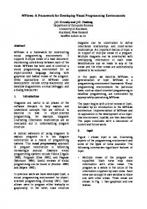
same node. The insertion of a text-box into a box containing two icons, is equivalent to the change of label of the edges connecting the two corresponding nodes. Analogously to the case of Lemma 3, besides the mapping from the IVMs to the GPs, our system also needs the reverse mapping from GPs to IVMs. Under the same admissibility conditions of Lemma 3, such a mapping always exists (see [12]), and, applied to a set of GPs q, returns a set of IVMs q', such that, assigned as input to the above mapping from the IVMs to the GPs, results into q itself. In Fig. 2.1 we show an example of query formulation in the iconic representation. The GMDB, the query and the Graphical Primitives are as in Fig. 5.1. We type the boxes containing icons corresponding to displayed nodes in bold. C. Hybrid Representation As we said before, the hybrid representation exploits a suitable combination of the above visual formalisms. In principle, any combination is admissible and its choice is guided by both the user needs and the application requirements. In the following we show a working example, in order to give the feeling of how such a kind of representation looks like. In particular, the example is based on integrating iconic and diagrammatic structures. Since we provided for both of them a formal semantics, the resulting semantics of the hybrid representation can be easily derived and will not be detailed in the following. The main idea is combining the unique features of diagrams for representing links and icons for resembling real word objects. In the following, we refer to a user interaction session, based on an extension of the GMDB used in the above examples (information on the workmen that repair cars are also available). The first display the user interacts with simply contains either the icons corresponding to the unprintable classnodes at the higher level in the hierarchy tree of the Typed Graph6 or the icons corresponding to the whole set of unprintable class-nodes. In the example in Fig. 5.2 the first option is chosen, and two icons are shown (nodes PERSON and CAR). In this hybrid approach the representation of the Typed Graph nodes is made through icons directly linked by edges (arrowhead or not, according to the Typed Graph rules), so that in the following we use the terms icon and node interchangeably and with the same meaning. In addition to the interaction mechanisms available in the iconic representation, additional operations are at user disposal. In particular, the open operation (top icon in the palette at the bottom left corner of the display) allows the user to "open" an icon and to access all its characteristics, i.e. the role-nodes linked to the icon itself. Moreover, through the zoom-in (resp. zoom-out) operation (third icon from the top in the palette), the user causes the system to display the hierarchy tree of an icon which is suitable for choosing one of the child (resp. parent) nodes. The find-path operation (second icon from the top in the palette) provides the user with the list of all the existing paths between a chosen pair of icons. Finally, the last icon in the palette allows writing selection conditions. Assume the user query is the following: "List the names and the addresses of all the workmen who repaired one of the cars owned by Mary". The user selects, among the available ones (Fig. 5.2(a)), the PERSON icon. Successively,
6 If a class-node is not involved in a hierarchy it is considered father of itself.
16
the user performs a zoom operation on such an icon (Fig. 5.2(b)), and selects the WORKMAN icon as well. Furthermore, the user asks for all the paths connecting WORKMAN and PERSON (Fig. 5.2(c)). Finally (fig. 5.2(d)), the user opens the icons of PERSON and WORKMAN , specifies the selection condition, and chooses the properties he or she wants to see in the final result. D. Atomic Queries and Deterministic Switching In the proposed multiparadigmatic environment the user can switch from one interaction paradigm to another during the query formulation, still finding the state of the query consistently updated in all the paradigms according to the semantics of his or her actions. To ensure this consistency, the switching is allowed only when the visual operations performed by the user have an unambiguous semantics in terms of Graphical Primitives. This is constantly verified by the system, that allows the user to change representation only when his or her query is atomic. Definition We say that a query q on the GMDB D is atomic if the database D', obtained by applying to D the Graphical Primitives corresponding to q, is admissible. fi The check of the query atomicity is obviously transparent to the user, who is prevented from changing representation while the query is not in the correct state for the switching. Furthermore, if the user tries to change representation when that is not allowed, the system suggests her/him several alternatives for completing the query in order to become atomic. In the following, the switching from one representation to another is denoted by SWITCHRi,Rj(D, q) , where D = is an initial GMDB, q is a query on D, and R i , R j are two visual representations. SWITCH is obtained by using the mappings introduced in the above subsections. For example, in the case of the switching from the form-based representation to the iconic representation, SWITCHForm-based,Iconic(D, q) represents the composition of the mappings: 1) FORM_TO_TG(t1,t2), which returns g and c; 2) FVM_TO_GP, which returns q expressed in terms of Graphical Primitives; 3) TG_TO_ICON, which produces the iconic representation of g and c; 4) GP_TO_IVM, which produces the iconic representation of q. We remind the reader that the mapping from GPs to both FVMs and IVMs does not necessarily produce a unique result. However, the following theorem establishes the necessary conditions for ensuring a deterministic switching between the representations. The proof is based on Lemmas 2, 3, and the analogous for the other representations (see [12]).
17
Å
n mo
Car
Person
Å
n p
Car
Workman
b
Å
Å
[+ a
Repairs
Å
nmnoo m
Car
Person Person
Age
b
n
Employee
Workman
%
Address
-
Å
n n A,B...Z
String
Å Repairs
-
[+ a
n mo n