resources e.g. Garp [1], Morphosys [2] and the Virtex II-Pro XC2VP4 and VP7 [3]. The system bus and the memory blocks require a careful study, since both ...
A hardware/software partitioning and scheduling approach for embedded systems with low-power and high performance requirements Javier Resano, Daniel Mozos, Elena Pérez, Hortensia Mecha, Julio Septién Dept. de Arquitectura de Computadores, Facultad de Informática, UCM, Madrid {javier1, mozos, eperez, horten, septien}@dacya.ucm.es
Abstract. Hardware/software (hw/sw) partitioning largely affects the system cost, performance, and power consumption. Most of the previous hw/sw partitioning approaches are focused on either optimising the hw area, or the performance. Thus, they ignore the influence of the partitioning process on the energy consumption. However, during this process the designer still has the maximum flexibility, hence, it is clearly the best moment to analyse the energy consumption. We have developed a new hw/sw partitioning and scheduling tool that reduces the energy consumption of an embedded system while meeting high performance constraints. We have applied it to two current multimedia applications saving up to 30% of the system energy without reducing the performance.
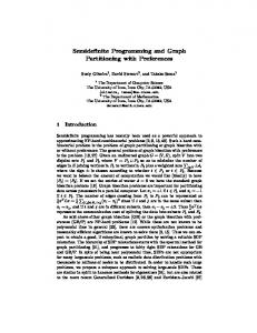
1 Introduction Low-power has become one of the major design concerns. First of all, the designer must guarantee that his design does not exceed the power constraints of the target platform, since it will generate heating problems. Moreover, due to the proliferation of portable, battery-dependent devices, low-energy consumption has become one of the key features for the success of a design. The current trend for portable embedded systems is to create heterogeneous systems, with one or more low-power processors, some additional hardware (hw) logic (ASICs and/or FPGAs), and some memory hierarchy. Current technologies allow creating the whole system in a single chip (SoC). One of the most important steps to carry out in order to implement an application over such a system is to partition the application functionality among the different processing elements. This process drastically influences both the energy consumption and performance of the system. Figure 1 presents a simple example where the partitioning process can lead to energy savings. If the designer selects the fastest solution (sch1), the execution time is 139 time-units and the energy 21 energy-units. However, if the deadline for the application is 150, the designer can try to find a slower solution that meets this constraint while consuming less energy. In this case sch2 would be
selected since its execution time is less than the deadline and its energy consumption is 16. Thus, the energy consumption decreases 25%.
Node1 Node2
PE1 PE2 T E T E 78 13 88 8 61 8 73 9
S c h 1
P E 1 P E 2
S c h 2
P E 1 P E 2
N 1
N 2
N 2 N 1 D e a d lin e
Fig. 1. Partitioning example. Two nodes must be partitioned between two Processing Elements (PE). T means time. E means energy. Sch1 and Sch2 are two selected solutions.
Since our partitioning tool is still under construction, currently we just support a software (sw) processor, an FPGA, a system bus and one or several memory blocks. However, partitioning an application to such a system is still a NP-complete problem. Moreover, there are several existing prototype platforms as well as commercial platforms that follow this scheme providing a sw processor and some reconfigurable hw resources e.g. Garp [1], Morphosys [2] and the Virtex II-Pro XC2VP4 and VP7 [3]. The system bus and the memory blocks require a careful study, since both elements can significantly affect the system performance and energy consumption, especially because both hw and sw performance are improving much faster than communication channels and memories do. In order to estimate accurately the impact of the memories and buses in the system performance and energy consumption their physical features must be taken into account. Ideally the vendor should provide either estimators or at least time and power models, but unfortunately, this is not always the case, then, time and power models are needed, some examples of existing useful models are [4] for USB, and PCI buses (just timing considerations), and [5,6] for memories. However, even after accurately estimating all the tasks, communications and memory accesses, computing the overall execution time it is not trivial, since it involves a scheduling that must take into account data and control dependencies as well as the accesses to the shared resources. Thus, we have developed a tool that schedules the tasks and the accesses to the system bus, and the shared memories during the partitioning process. This scheduling is the only way to accurately evaluate a solution, since otherwise, it is impossible to determine the impact of the communications or the delays introduced due to the conflicts on the accesses to shared resources (In [7] this problem is explained in detail). In addition, this scheduling prevents the need for arbitration logic in the bus controllers. Since the scheduler is integrated in a partitioning tool that must evaluate a great amount of different partitions one of our major concerns was to achieve near-optimal scheduling without increasing significantly the execution time of the partitioning tool. The rest of the paper is structured as follows: section 2 presents an overview of the related work; section 3 explains in detail the format of the initial specification for our partitioning tool; section 4 describes the cost function that steers the design space exploration; sections 5, 6, and 7 explain how the energy, execution-time and hardware area are estimated for a given partitioning. Section 8 presents the experimental
results and finally section 9 remarks some conclusions as well as future work to be done.
2. Related Work Hardware/software partitioning is a very well known problem. Several partitioning tools have been proposed in literature (e.g. [8, 9]). Most of these previous approaches accomplish the partitioning problem at a high abstraction level, adding the platform low-level details and scheduling the tasks on the processing elements (PEs) in a subsequent step called co-synthesis. Moreover, even during co-synthesis often the communications between different PEs are neglected, thus, these communications are included in a following step called communication synthesis. After these three steps the resultant solution is co-simulated, and likely, the results will not be the expected, so the process will have to start again with another solution. The main problem of this approach is that some of the features neglected during partitioning are critical for the system performance. Thus, it is almost impossible to found near-optimal solutions when communications are neglected during the partitioning process. Another lack of most of the existing approaches is that they just consider either hardware area or execution time minimization. However, as mentioned in the introduction, currently minimizing the energy consumption is often one of the more important designer concerns. Recently several scheduling and/or partitioning approaches for multiprocessors have been presented. They attempt to minimize the system consumption either applying Dynamic Voltage Scheduling (DVS) or applying different supply voltages to each processor; some of the more relevant are [10, 11,12]. DVS techniques schedule the voltage supplied to each processor during its execution. This is a powerful way to achieve power savings, since in CMOS technologies the power consumption decreases quadratically with the power supply. However, currently there is not support for DVS in most of the commercial processors, and to the best of our knowledge, there is not support at all for DVS in FPGAs platforms. Hence, nowadays, this is not a feasible approach for hw/sw co-design. [13] is the first hw/sw partitioning tool for low-power that we have found, it starts from a full sw implementation in a microprocessor (PP), and reduces the energy consumption migrating part of the functionality to hw, the energy savings are achieved turning off the PP (in addition clock gating is applied in the hw partition). This approach does not perform a full partitioning design exploration. Moreover, it expects some data for the designer, like the number of ALUs, multipliers, shifters, etc., based on some previous designer experience, so the results of the partitioning will highly depend on the designer capabilities. PAP [14] is a recent partitioning tool that attempts to minimize the hardware area while meeting the timing and power constraints, thus they do not minimize the overall energy consumption but take care that infeasible solutions (those that consume more power than the allowed by the platform) will not be selected. Finally, in [15] a scheduling technique for dynamically reconfigurable FPGAs with support for partial reconfiguration is presented. The scheduling process attempts to minimize the energy consumption optimising the
number of partial reconfigurations. However, this scheduling is carried out after the partitioning process, hence, most of the flexibility is lost since the partition has been previously fixed. According to this paper, currently, FPGAs dynamic reconfiguration is extremely power inefficient, since in their experiments up to 50% of the FPGA energy consumption was due to these reconfigurations. Although there is substantial work spent in partitioning and scheduling for lowpower, we believe that our approach is the first one that accomplishes a deep design space exploration of the partitioning and scheduling process for hardware/software low-power embedded systems, attempting to meet the real-time timing constraints while minimising the overall system energy consumption, and including the system bus, and memories in the performance and energy consumption estimations.
3 Initial Specification The initial specification is described as a Directed Acyclic Graph (DAG), where each node represents a computational task, or an access to the shared memory, and the edges correspond to dependencies among the nodes. Three different dependencies are considered, namely: communication, internal, and temporal dependencies. A communication dependency edge (CDE) either connects two nodes of PEs, or corresponds to a memory access; therefore, it represents a data transfer that must be carried out using the system bus. An internal dependency edge (IDE) connects two nodes allocated in the same PE, thus, it represents a data transfer, but in this case there is no access to the system-bus. A temporal dependency edge (TDE) represents a dependency between two nodes in the same PE that has been imposed by the scheduler. Each node of the graph must be characterized by its execution, power and area estimations for every possible platform. Each CDE is tagged with the amount of data to be transferred, and the execution time and energy consumption estimations. These estimations must include both the access to the system bus, and when needed, the access to the shared memory.
4. Cost Function The cost function of a codesign system typically includes different elements like the hw area, the execution time, the energy consumption, or the amount of communications. One of the more difficult issues when designing a partitioning system is how to mix all these completely different magnitudes into a cost function that should be able to lead the design space exploration in a near-optimal fashion. In literature several codesign approaches can be found where cost functions are built like the following: n
n
n
F ca *¦i 0 Areai � ct *¦i 0Timei � ce *¦i 0 Energyi
(1)
Thus, for a given partition, each node of the DAG is characterizes with a number for every magnitude considered (three in this example). The cost function is then easily computed adding these numbers and multiplying them by some coefficients. Often, the user must fix these coefficients, thus, he has to identify the equivalence between a second, a Joule, and a mm2. There is not an evident criteria about how to fix these coefficients, therefore these heterogeneous cost functions often lead to inefficient design-space explorations. In order to avoid this problem, our partitioning tool is led by a straightforward cost function that can be identified either with the energy consumption, the hw area or the execution time. Thus, the tool supports three different design-space explorations; the first one attempts to find the solution that consumes less energy and meets three restrictions, namely, maximum execution time, maximum hardware area and maximum power consumption restrictions. The first restriction guarantees that the application meets its real-time deadline; the second guarantees that there are enough hw resources to implement the hw partition; and the third restriction prevents the heating problems. If the system is not battery-dependent, the cost function can be identified either with the execution time, or with the area. When the execution time is selected as cost function, the tool attempts to find the fastest solution that meets the given area and power restrictions, otherwise, when area is selected, the tool will try to find the solution with less hw area that meets the execution time and power restrictions. It is up to the designer to decide which one is the goal of the design-space exploration. Table 1 shows all the possibilities. Table 1. Cost functions and restrictions that can steer the design space exploration
Available Cost Functions Energy Time Area
Available Restrictions Time Energy Area Power
5. Energy Consumption Estimations First of all, each node and each edge of the DAG must be characterized with its energy consumption for every possible processing element. These estimations must be carried out using the tools provided by the vendors if possible; otherwise generic power models must be applied. In addition to the energy consumption due to the nodes execution (including those nodes that represent the accesses to the shared memory) and communications, we assume that the PEs also consume energy when they are idle. If the PE is a processor, the power consumption in the idle state is commonly provided in the data sheet. The energy can be computed multiplying the power by the idle time. The same approach is used for the memory blocks. If the PE is implemented in the FPGA and clock gating is applied to it, the power that consumes when is idle will be just the device quiescent power. Otherwise, if clock gating is not implemented the logic dissipates more power apart from the quiescent power,
since the clock signal continues switching. This case is estimated considering the power consumption of the circuit when the toggle rate of the inputs is set to 0, thus we assume that when the circuit is idle all the inputs are fixed, if this is not correct, a proper toggle rate should be estimated profiling the system. Besides the energy considerations, the partitioning tool must check if a given partition meets the power dissipation constraints of the platform. To this end, the average power consumption of each node and each communication is included in the DAG.
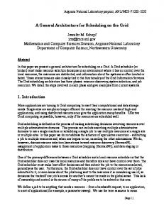
6. Execution Time Estimations The execution time estimator, receive as input a given partitioning where the execution time of each node and each access to the system-bus have been previously estimated (we assume cycle accurate estimations). Nodes representing accesses to the shared memory have always a 0 time-units execution time assigned, since the latency of accessing the shared memory is considered as part of the communication delay. With this input the estimator schedules the execution of every node as well as all the accesses to the system bus. This scheduling is a NP-complete problem, however the estimation must be done as fast as possible since it has to be computed for every explored partition. Thus, we have developed a fast heuristic, based on list scheduling techniques, which provides a near-optimal scheduling with a low computational complexity (O(N2)). Fig. 2 depicts the scheduling pseudo-code. A) Assign a weight to each node. B) Choose the execution order for the SW nodes. C) Recalculate the weights taking into account the new dependencies. D) Schedule those nodes that are not waiting for a communication. E) While there is a communication waiting for execution do: E1) Choose one communication and schedule it. E2) Schedule those nodes that are not waiting for a communication Fig. 2. Scheduling heuristic pseudo-code
Step A: The weights are used to steer the scheduling process trying to minimize the global execution time. The weight of a node is the maximum time-distance from that node to the end of the execution in the initial graph. This distance is computed carrying out an ALAP scheduling that takes into account all the dependencies. Thus, those nodes, which are in the DAG critical path, have higher weights. Step B and C: The initial DAG allows parallel execution between their nodes, but those nodes assigned to sw must be executed sequentially. The sw execution order is decided sorting the nodes by their weights. To impose this order new TDE dependencies are added to the initial DAG. It is easy to prove that this sw execution order does not allow the new dependencies to create cycles in the graph. Since these new dependencies can significantly affect the system performance, a new weight is assigned to each node. These weights are computed in the same way that in step A, but considering the new dependencies.
Steps D and E: An enhanced list-scheduling heuristic that attempts to minimize the global execution time has been developed for the scheduling process. This heuristic decides when each node and each communication is executed, assigning to them a tstart and a tend times. The motivation of the heuristic is to detect the system bus access conflicts and the delays created by them. The scheduling starts assigning tstart = 0, and tend=tex to the first node, where tex is its execution time in the partition where it has been assigned. Then the algorithm continues scheduling the successors of the first node. A greedy policy is followed to schedule nodes while there is no need for hw/sw communications. When a scheduled node requests a hw/sw communication with another node this request is stored in a list. Once all the nodes that do not need a hw/sw communication have been scheduled, one of the requested communications is selected and scheduled. There are two selecting criteria (E1): If at a given time t the system bus is not carrying out any communication and there is just one previous request, the communication channel is assigned to this request, and the bus is tagged as busy until this communication ends. Otherwise, if there is more than one request, the one with the greatest weight will be selected. The weight of a communication is computed as the weight of the destination node plus the time needed to execute the communication. Once the selected communication has been scheduled the graph is examined (E2) and all the nodes that can start their execution without waiting for another HW/SW communication are also scheduled. The loop continues until all the communications are scheduled.
7. Area estimation We apply the following equation to estimate the area needed to implement the nodes assigned to hw in the FPGA:
Area
¦
N �1 i 0
Ai � Adriver � Acontrol � Astorage
(2)
Ai is the area of the node i. Adriver is the area needed to implement the communication driver. Ai and Adriver are estimated from a core library. When a new core is added to the library its area is estimated using a synthesis tool. Acontrol is the area needed for the control logic that schedules the communications. In this approach the scheduling control is assumed by a state machine, so the area requested is estimated as a function of the number of communications. Astorage is the area needed for storing the data to transfer until a communication is executed. This storage space is computed during the communication scheduling. During this process a record keeps the maximum storage space required.
8. Results and Analysis All the estimators has been integrated into a partitioning tool based on genetic algorithms (GA) [16]. This tool creates a random initial population of valid solutions. A solution is valid if meets the given area, time and power constraints. Invalid solutions are rejected to save computational time, as well as to prevent the algorithm from converging to a non-valid area. During the design space exploration solutions evolve by reproducing themselves, generating new offspring of solutions. The crossover and the mutation operators carry out the reproduction process. Population is kept constant deleting the solution surplus. The 80% of the survivors are selected choosing the best solutions, and the 20% remaining is randomly selected in order to prevent a premature convergence. The designer can establish the population and the crossover and mutation probabilities. In addition, he can also select the cost function (between time, energy, and area) and fix the area, time and power restrictions. The partitioning tool allows the designer to select between two different scheduling modes, the first implements our heuristic while the second carries out a full search of the design space applying a branch&bound (b&b) algorithm, hence this mode guarantees that always the best schedule is found. As a first experiment, in order to validate our heuristic, we have run the partitioning tool in these two different modes for a set of 100 randomly generated DAGs. These DAGs were created using the TGFF tool [17], and their sizes are limited to any number between 10 and 20 nodes (for greater sizes it is not feasible to apply the b&b algorithm). The results obtained show that the b&b algorithm finds slightly better schedulings (on average 10% less execution time), but at the price of increasing 800 times the computational time needed to carry out the partitioning process (which it is reasonable since it performs a full search of the design space). These results confirm that our scheduling heuristic finds near-optimum schedulings with an almost negligible overhead. In this experiment the average time needed to schedule one of the DAGs with our heuristic was less than 2.5 Ps using a Pentium II running at 350 MHz. In our second experiment we attempt to compare the results obtained when using the energy and the execution time as cost function. To this end, we have analyzed two current multimedia applications, namely a JPEG decoder and a pattern recognition application that compute the Hough Transform of a matrix of pixels in order to find simple geometric patterns. The Hough Transform is commonly applied in robotics and astronomical data analysis. It is very simple to reduce the energy consumption when it is also possible to reduce the performance. Therefore, in this experiment we check whether it is possible to reduce the energy consumption while keeping almost the highest performance. Hence, we have run first the partitioning tool using the execution time as cost function to find the fastest solution. Then, we have rerun it using the energy instead of the time as cost function, but this time we have imposed that the solutions must be at most 10% slower than the fastest solution found in the previous step. Therefore, the tool is going to found the solution that consumes less energy while keeping almost the highest performance. For this experiment we have estimated the energy, execution time, area and power consumption of the application using the XILINX Foundation
5.i tool for the FPGA and the system bus, an ARM processor simulator for the sw processor and a 128 MB MICRON SRAM memory datasheet for the shared memory. Each application has been partitioned to a platform composed by a XILINX Virtex FPGA, an ARM processor running at 233 MHz, a 128 MB memory block and a system bus with 16 bit width and clocked at 33 MHz. The measurements were repeated 5 times for 5 different FPGA sizes. The results are shown in table 2. It is remarkable that we can decrease up to 30% the energy consumption (on average 17%), whereas the execution time remains almost the same (it increases less than 3% on average).
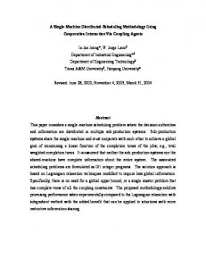
Table 2. Results for the Pattern Recogniton Application (a) and the JPEG decoder (b). T1, and E1 are the execution time and the energy consumption for the fastest solution, whereas T2 and E2 correspond to the solution found using the energy as cost function.
a) Pat. Rec. FPGA1 FPGA2 FPGA3 FPGA4 FPGA5
T1 8412 9581 9940 10841 11069
T2 8493 9586 9945 11027 11519
Time % + 4% + 0% + 0% + 2% + 4% + 2%
E1 188324 222294 226020 247887 256264
E2 164147 182407 186133 216630 227436
Energy % - 13% - 20% - 18% - 13% - 11% - 15%
T1 927 1480 2329 2801 3848
T2 950 1490 2385 2898 4183
Time % + 2% + 1% + 2% + 3% + 8% + 3%
E1 15354 16400 14265 13200 8938
E2 15194 14800 10947 9800 6160
Energy % - 7% - 10% - 23% - 26% - 30% - 19%
Average b) JPEG FPGA1 FPGA2 FPGA3 FPGA4 FPGA5
Average
9. Conclusions and Future work We have presented the first (to the best of our knowledge) hw/sw partitioning tool that can steer the design space exploration of the partitioning process to minimize the energy, the execution time or the area. In addition this is one of the few tools that accomplishes a full scheduling during the partitioning process including the accesses to the system bus and shared memories. This scheduling is the only way to accurately estimate the goodness of a given partition. We believe that this tool can be especially useful to decrease the energy consumption of a given application while meeting hard real-time constraints. Thus, we have applied our tool to two current multimedia applications, saving up to the 30% of the energy consumption, whereas the performance remains almost constant. Moreover, it must be remarked that is unimportant that the performance slightly decreases as long as the timing constraints are met.
Although our tool fulfills the requirements to partition an application to several existing platforms, several extensions are needed to apply it to platforms with multiple processors and more complex interconnection networks.
Acknowledgements This work has been partially supported by Spanish Government research grant TIC2002-00160.
References 1. J. R. Hauser and J. Wawrzynek, "Garp: A mips processor with a reconfigurable coprocessor," in IEEE Workshop on FPGAs for Custom Computing Machines, pp. 24--33, 1997 2. H. Singh et al, “MorphoSyS: An Integrated Reconfigurable System for Data-Parallel and Computation-Intensive Applications”, IEEE Trans. on Computers, pp. 465-481, Vol. 49, No. 5, 2000. 3. http://www.xilinx.com 4. M. Gasteier, M. Munich, M. Glesner. “Generation of Interconnect Topologies for Comuni cation Synthesis”, DATE’98, pp. 36-42. 1998. 5. K. Itoh et al., “Trends in Low-Power Ram Circuits Technologies”, Proc. IEEE, 83(4):524-
543, Apr. 1995. 6. M. Kamble and K. Ghose, “Analytical Energy Disipation Models for Low Power Caches”, Proc. Int’l Sym. Low Power Electronics and Design, p. 143, Aug. 1997. 7. J. Resano et al, “Analyzing Communication Overheads during Hardware/Software Partitioning”, ESCODES’02, pp. 16-21, 2002. 8. R.P. Dick and N.K. Jha, “CORDS: Hardware-Software Co-Synthesis of Reconfigurable Real-Time Distributed Embedded Systems”, ICCAD’98, pp. 62-67, 1998. 9. J. Noguera, R.M. Badía, “A HW/SW partitioning algorithm for dynamically reconfigurable architectures”, DATE’01, pp. 729-734, 2001. 10.P. Yang et al., “Energy-Aware Runtime Scheduling for Embedded-Multiprocessors SOCs”, IEEE Journal on Design&Test of Computers, pp. 46-58, 2001. 11. G. Qu et al., “Power Minimization using System-Level Partitioning of Applications with Quality of Services Requirements”, Proc of Int. conf. on CAD. pp. 343-346, 1999. 12. I. Hong et al., “Power Optimization of Variable-Voltage Core-Based System”, IEEE Trans. on CAD of Integrated Circuits and Systems, vol. 18, no 12, pp. 1702-1714, 1999. 13.J. Henkel, “A low power hardware/software partitioning approach for core-based embedded systems”, DAC’99, pp. 122-127, 1999. 14.R. Mahapatra and P. Vijay, “PAP: Power Aware Partitioning for Reconfigurable System”, To be published in Proc. of HPCA Workshop 2003, feb. 2003. 15. L. Shang et al., “Hw/Sw Co-synthesis of Low Power Real-Time Distributed Embedded Systems with Dynamically Reconfigurable FPGAs”, ASP-DAC’02, pp. 345-360, 2002. 16. J. Holland. “Adaptation in natural and artificial systems”, MIT Press, 1992. 17. R.P. Dick et al, “TGFF: Task Graphs for Free”, Int’l Workshop HW/SW Codesign, pp. 97101, 1998