IEEE TRANSACTIONS ON INSTRUMENTATION AND MEASUREMENT, VOL. 55, NO. 5, OCTOBER 2006
1725
A High-Performance Imaging and Control System for a Micromirror-Based Laser-Scanning Endoscope Device Panagiotis G. Papageorgas, Dimitris Maroulis, Giorgos Anagnostopoulos, Hansjörg Albrecht, Bernd Wagner, Dimitris K. Iakovidis, and Nikiforos G. Theofanous
Abstract—A novel reduced-size endoscope system based on a laser-scanning technology has been developed by the authors. This system employs specific silicon micromirrors and ensures a high-resolution color imaging with improved characteristics. A critical part of the device is its data-acquisition, control, and processing (DACP) system for real-time handling of the collected digital images. The supporting software is an event-driven application for the MS-Windows operating system that incorporates important features such as improved portability through the open PC architecture, cost effectiveness, high performance, and efficient scalability by using a symmetric multiprocessing desktop computer. In this paper, a presentation of the DACP system is performed with a focus in the software developed, which exploits the multithreading technology, resulting in a high-performance endoscope device. Index Terms—Data acquisition, digital imaging, endoscope, laser scanning, micromirror, multiprocessing, multithreading, real time.
I. I NTRODUCTION
M
ODERN optical endoscopes make use of new advances in the technology of miniaturized imaging systems, providing important benefits to the diagnostic examinations and surgeries that require continuous visual monitoring [1], [2]. They can be classified into three major categories, depending on the image-sensor placement and the technology used. The first category employs a combination of optical fibers and a color charged couple device (CCD) or CMOS image sensor, embedded in or distant from the endoscope tip; these devices exhibit the disadvantages of a low resolution and poor sensitivity currently achieved with the embedded sensors, while the devices with the image sensors located outside the endoscope tip have Manuscript received January 26, 2005; revised March 28, 2006. This work was supported by the Commission of European Communities: European Project BIOMED-2 “MEDEA—microscanning endoscope with diagnostic and enhanced resolution attributes,” under Contract BMH4-CT97-2399. P. G. Papageorgas was with the Department of Informatics and Telecommunications, University of Athens, 15784 Athens, Greece. He is now with the Department of Electronics, Technological Education Institute of Pireaus, 12244 Athens, Greece (e-mail:
[email protected]). D. Maroulis, G. Anagnostopoulos, D. K. Iakovidis, and N. G. Theofanous are with the Department of Informatics and Telecommunications, University of Athens, Panepistimiopolis, 15784 Athens, Greece (e-mail:
[email protected];
[email protected];
[email protected];
[email protected]). H. Albrecht is with the Laser- and Medical-Technology gGmbH (LMTB), 14195 Berlin, Germany (e-mail:
[email protected]). B. Wagner is with the Fraunhofer Institute of Silicon Technology (ISIT), 25524 Itzehoe, Germany (e-mail:
[email protected]). Digital Object Identifier 10.1109/TIM.2006.880305
increased chromatic aberrations. The second category makes use of a thin-image fiberscope constructed with a single fiber or a bundle of fibers with an overall diameter of less than 0.2 mm, while the main drawback is the low resolution achieved. Finally, micromachine technologies based on microelectromechanicalsystem devices [3]–[11] are applied for laser-scanning in order to achieve high resolution in small dimensions. Laser-scanning microscopy and optical coherence tomography are two well-known laser-scanning-imaging technologies that are used in a variety of biomedical applications. Systems of this kind are usually designed for microscopy applications [3], [4], providing a field of view in the order of 1 mm2 and, resolutions in the order of 1–3 µm, while they normally utilize one wavelength for illumination and detection. The optical design of these systems ensures a considerable magnification by using objective lenses with an appropriate numerical aperture and focal length, enabling the use of laser-scanning mirrors with small dimensions. The dimensions of the scanning mirrors are determined from the diameter of the laser spot in the object area, the objective lens used, and the walking effect of the scanning laser spot on the second deflecting mirror when two scanning mirrors are used in a serial arrangement. Restrictions in the development of color lasers have been the main obstacle for the realization of laser-scanning devices for endoscopy applications. Recent advances in the manufacturing of green and blue solid-state lasers of adequate power and stability have opened the way for the development of color laser-scanning display and imaging systems. The laserscanning endoscope developed, which is supported with the data-acquisition, control, and processing (DACP) system under presentation, is a first realization of color laser scanning for endoscope imaging. This laser-scanning endoscope system has been designed for color macroendoscopy applications, where the field of view is in the order of 10–20 mm2 , with a resolution of at least 50 µm and image rates in the order of ten frames per second. The microscanning-endoscope system under consideration is based on micromirrors that deflect a composite laser beam for red, green, blue (RGB) color imaging. This microscanning endoscope, which can have small dimensions for the endoscope head, provides high-resolution color imaging with full-motion capabilities. Compared to conventional endoscope devices, it presents a number of advantages, such as the reduction in the cost of the light source, and the high resolution achieved
0018-9456/$20.00 © 2006 IEEE
Authorized licensed use limited to: IEEE Xplore. Downloaded on November 12, 2008 at 04:25 from IEEE Xplore. Restrictions apply.
1726
IEEE TRANSACTIONS ON INSTRUMENTATION AND MEASUREMENT, VOL. 55, NO. 5, OCTOBER 2006
TABLE I MICROSCANNING-ENDOSCOPE SPECIFICATIONS
Fig. 1. System concept of the microscanning endoscope.
combined with a large field of view. Moreover, the laserscanning process has inherent advantages such as the avoidance of blurring from a target movement, bright illumination, and small aperture, resulting in a large depth of focus. The aim of this paper is to present the design of the DACP system with its software and hardware parts, which support the operation of the laser-scanning endoscope system. In what follows, we briefly describe the general characteristics of the endoscope device and the micromirrors employed, and in the sequel, we provide the main and more important information about the DACP system. II. F UNCTIONAL D ESCRIPTION OF THE M ICROSCANNING I MAGING D EVICE The overall setup concept is presented in Fig. 1. Emanating from the illumination subsystem, three laser beams with wavelengths in the red (655 nm), green (532 nm), and blue (473 nm) spectrum are collimated and guided through a multimode fiber to the endoscope tip, which is the distal part of the endoscope device that is inserted inside the patient’s body. With this tip, the flying-spot scanning of the target tissue is performed together with the collection of the back-reflected/scattered light by means of the associated optics and a light-collection fiber. Inside the tip, microoptical components have been integrated to perform an appropriate focusing, to guide the illuminating and back-scattered light, and to separate their optical paths to reject the stray light. The two scanning micromirrors have been constructed using a microelectromechanical-system technology. These micromirrors can be deflected electrostatically in directions orthogonal to each other in response to the high-voltage signals applied from the control subsystem. The micromirrors are used for the scanning and descanning of the composite laser beam directed onto the targeted object and the backscattered light beam, respectively, in a raster mode of operation.
Fig. 2. Outer and inner parts of the endoscope head. The inner part acts as a carrier for the tilting mirrors, the imaging lenses, and the prism/beam splitter combination. The illumination and measuring fibers are connected to the inner part from the right side and are not shown in this picture.
The optical signal backscattered from the scanning “flying spot” is collected with an optical assembly situated inside the microscanning tip and is sent to the detection fiber. The socollected light is guided through the fiber to the optical detection unit, which is based on specific avalanche photodiodes. At the output of the optical detection unit, the data-acquisition board simultaneously digitizes the three electrical signals (one for each color) and generates the control waveforms for the scanning mirrors. The software that has been developed programs the data-acquisition board, creates the appropriate scanning waveforms, processes the sampled data stream, and reconstructs, displays, and stores in real-time the associated two-dimensional (2-D) images for further processing and analysis. Various specifications of the microscanning endoscope realized in our paper are presented in Table I. III. M ICROMIRROR D ESIGN AND F ABRICATION The use of a bulk silicon technology for the fabrication of electrostatically driven torsional micromirrors appears rather frequently in the technical literature [6], [7]. The major disadvantage of this kind of micromirrors is their fragility that prevents their extended use in practical applications. The micromirrors that have been designed, fabricated, and tested for the present scanning device are more compact and can meet the requirements of fast 2-D scanning with large scan angles and high shock resistance. This is achieved by combining the bulk silicon technology with metal-surface micromachining [8], [9]. A photograph of the outer and the inner parts of the endoscope tip with its micromirrors is given in Fig. 2.
Authorized licensed use limited to: IEEE Xplore. Downloaded on November 12, 2008 at 04:25 from IEEE Xplore. Restrictions apply.
PAPAGEORGAS et al.: IMAGING AND CONTROL SYSTEM MICROMIRROR LASER-SCANNING ENDOSCOPE DEVICE
Fig. 3.
1727
Block diagram of the data acquisition and control system.
Two micromirrors of this kind are employed in the endoscope device developed in a serial arrangement. The first micromirror, which has a size of 3 × 4 mm2 , is used for the line-scanning operation and is driven in a resonant mode at about 1.2 kHz in order to achieve the maximum possible mirror deflection. The second mirror has a size of 4 × 4.8 mm2 and is used for the frame-scanning operation with its movement controlled by a sawtoothlike waveform. Both mirror types, the slow axis mirror as well as the fast one are capable of mechanical deflections up to ±3◦ . For macroendoscopy applications, the large imaging areas that must be scanned impose a low numerical aperture for the objective lens and considerable larger laser-spot diameters compared with the ones used in confocal laser-scanning microscopes [3], [4]. These parameters with the additional consideration of the walking effect that is always present in the serial combination of two scanning mirrors puts a lower limit to the micromirrors size, thus resulting in the increased dimensions of the micromirrors developed. IV. DACP S YSTEM The microscanning devices for optical coherence tomography and confocal laser-scanning microscopy currently existing
in the market are normally closed systems, while the information about the development of the data collection and processing systems is restricted and seldom presented in the literature [12], [13]. On the other hand, the software developed and presented in this paper combines the multithreading technology supported in the recent versions of the Microsoft Windows operating systems with a standard data-acquisition board and commercially available software tools for the implementation of a real-time control, image acquisition, and processing system based on the open system PC architecture. The block diagram of the DACP system of the present endoscope device is depicted in Fig. 3. This DACP system simultaneously digitizes the three electrical signals (one for each color) generated from the optical detection units of the backscattered light signal and generates the two analog waveforms needed for the position control of the scanning micromirrors used. After the digitization, the reconstruction, preprocessing, and display operations are performed in real time with the multiprocessor PC system employed. The principal module of the subsystem for data acquisition and control is the PCI-6110E data-acquisition card of National Instruments Co. With this card, the simultaneous digitization of the three analog signals can be realized at a maximum sampling rate of 5 Msamples/sec with a 12-bit resolution. Also, the
Authorized licensed use limited to: IEEE Xplore. Downloaded on November 12, 2008 at 04:25 from IEEE Xplore. Restrictions apply.
1728
IEEE TRANSACTIONS ON INSTRUMENTATION AND MEASUREMENT, VOL. 55, NO. 5, OCTOBER 2006
generation of two control waveforms can be performed using the available digital to analog converters at a maximum update rate of 2.5 Msamples/sec on both channels simultaneously with a 16-bit resolution. The PC platform used was a dual-processor (450-MHz Intel Pentium III) symmetric multiprocessor (SMP) system. The operating system was the Microsoft Windows NT 4.0 with a multiprocessing kernel that supports the parallel execution of the program threads into the available processors. For this purpose, the software of the microscanning system has been developed as a multithreaded program ensuring a predictable response to events and commands through the user interface, while the parallel execution of the program threads provides an increased processing power for the real-time system operation. After the digitization of the collected signals, the images are reconstructed and displayed in one window of the main panel of the graphical user interface (GUI). The raw images are enhanced by appropriate preprocessing, displayed in the second window of the GUI’s main panel and stored in an array of hard disks for further analysis. The developed GUI with the two windows of the main panel for image display can be seen in Fig. 5. This GUI combines simplicity and effectiveness and provides the user with the necessary controls over the acquisition and preprocessing procedures through appropriate buttons and various menu options together with direct control of the various parameters for the generated waveforms. The multithreaded software developed is capable of handling the preprocessing, display, and storage operations in real time, while at the same time displays the acquired and processed images at rates of up to 20 frames/sec with a resolution of 500 × 500 color pixels. It is of note that the Windows NT is not a real-time operating system [11], [14] and does not have the necessary mechanisms that could be used from a program in order to “guarantee” the performance required. However, the design of Windows NT includes enough real-time operating-system elements (such as a priority-driven preemptive scheduler) to ensure that the developed application exhibits a predictable and “acceptable” performance [15], [16]. For the DACP software developed in this paper, the predictability has been indeed achieved without any noticeable performance degradation. Considering the above, a number of steps have been taken in the direction of performance improvements, including the employment of an SMP PC platform and the use of the multithreading technology, [17]–[19] in combination with an array of hard disks for fast data storage and retrieval.
V. M ETHODOLOGY AND P ERFORMANCE C ONSIDERATIONS FOR THE S OFTWARE D EVELOPMENT A. Software Structure The software for the present DACP system was developed using the Integrated Development Environment C-Builder 4.0 from Borland Co. This environment supports a C++ compiler for 32-bit windows applications with satisfactory graphical user interfaces using a simple syntax for defining and addressing objects.
Using the aforementioned compiler, the DACP software has been realized in a modular way that provides to the programmer an abstract layer of application programming interface (API). With this API, the programmer can develop the application software for the specific endoscope. This API has been developed as a set of functions that can be grouped into the following main-library categories. 1) GUI. This library provides the basic functions for the GUIs that are necessary for the system operation. With the GUIs developed, various parameters of the dataacquisition process can be selected as well as the appropriate control waveforms, the image-processing algorithms applied and the file storage and retrieval of the acquired data. 2) Image preprocessing. The corresponding library offers functions related to the reconstruction of the 2-D images from the acquired data, the synchronization of the data acquisition with the scanning operation, and the application of lookup tables for the transformation of the collected 12-bit data to 8-bit ones, per color and per pixel, together with the data rearrangement for the bidirectional scanning operation. The 12- to 8-bit transformation is performed, because most of the graphics cards support the display of 24-bit color images. After the frame reconstruction, the specific image is transformed in the bitmap independent format (BIF), and an image handler is associated with it. The BIF has been utilized due to the freedom it provides for handling 24-bit images (8-bit color depth) with the desired resolution and because it is directly supported by the image-processing library employed. 3) Data acquisition. This library supports the data acquisition by selecting the various parameters, such as the triggering mode, the sampling frequency, the gain settings, and the phase difference between the slow and the fast mirror. This library was based on the NIDAQ 6.06 library that accompanies the PCI6110E acquisition card and provides the necessary drivers for the programming of the data acquisition and waveform-generation procedures. The data-acquisition software module was designed as an asynchronous event-driven process, in which the data is transferred from the buffer memory of the acquisition card to the main memory using the direct memory access (DMA) technique with minimum CPU intervention. 4) Image processing. The image-processing library supports many primitive functions such as mask filtering, convolution filtering, and thresholding. It is based on the image-processing library, which has been developed by Intel Co and takes full advantage of the MMX technology, which incorporates an inherent parallelism in execution of the new streaming singleinstruction multiple-data instructions that the newer Pentium CPUs provides. This technology improves significantly the computational performance of the imageprocessing functions used. 5) Image display. With this library, the fast display of the images in a window with a user-defined resolution is achieved in real time using the Microsoft DirectX 7.0
Authorized licensed use limited to: IEEE Xplore. Downloaded on November 12, 2008 at 04:25 from IEEE Xplore. Restrictions apply.
PAPAGEORGAS et al.: IMAGING AND CONTROL SYSTEM MICROMIRROR LASER-SCANNING ENDOSCOPE DEVICE
API for direct access of the local memory of the videographics card. 6) Control waveforms generation. This library supports the generation of the two analog waveforms with the dataacquisition board digital to analog converters, which control the scanning operation of the two mirrors with a proper adjustment of their characteristics (frequency, shape, amplitude, spectral content). For the horizontal (line) mirror, a sinusoidal waveform is produced at the frequency of the mechanical resonance, while a triangular waveform is generated for control of the vertical (frame) mirror. As the generation of these two waveforms is asynchronous to the execution of the other software tasks, it is activated by a call and programed for infinite iterations before the control is returned to the other tasks. Once the waveform generation has been activated, it can be paused or stopped only by another call to this task. The waveforms are synthesized using appropriate algorithms according to the physical characteristics of the mirrors, the user requirements, and the limitations of the dataacquisition card. 7) Multithreading support. This library is based on the WIN32 API for the generation and control of a number of threads for the part of the software that is executed in parallel into the available CPUs. The source data for each thread comes from individual frames. This library uses the WIN32 API for the scheduling and management of the threads created. 8) Fast disk access. In the corresponding library, the fast disk storage and retrieval of the acquired data is achieved in real time using the disk-striping (RAID-0) technique provided by Windows NT. The collected images are recorded in real time in an array of hard disks for subsequent analysis and/or retrieval. The hard-disk storage-bandwidth requirements of the system for a real-time operation have been estimated to be about 22.5 MB/sec for the recording of three channels (for the three colors) at 5 Msamples/sec and per channel with 8-bit color depth. Redundant arrays of independent disks (RAID) deliver a higher throughput, capacity, and availability than the throughput of a single large disk by hooking together arrays of small disks. For our system, we have selected the RAID-0 format, which offers an increased throughput by using two small computer systems interface (SCSI) disks. With the striping technique, the data is stored (or retrieved) in a number of disks in parallel, and therefore, the throughput increases in almost a scalable way with the number of disks utilized when compared to the throughput of a single disk. In the system used, the sustained (without gaps) throughput with one disk has been measured and found to be about 13 MB/sec, while with the disk-striping technique, for two identical disks, this rate has increased to about 24 MB/sec. The disk throughput measurements have been performed with the IPEAK Storage performance profiling software provided by Intel Co. With the above sustained disk-storage throughput, the DACP system provides the continuous (with no gaps) recording of the uncompressed collected images in real time. We have selected hard
1729
disks with SCSI interface due to the large available bandwidth and the minimum CPU processing power required in comparison with the more popular Ultra ATA interface. There are two important issues that affect the maximum throughput achieved with the disk-striping technique. The first one is the degree of striping, which is the number of independent disks used (more disks results in larger sustained throughput). The second and most important is the stripe unit size, which is the maximum amount of logically contiguous data stored (or retrieved) on each disk. Stripe unit size of 32 KB has given the best results for our real-time application. It is worth mentioning that the Windows NT File system uses by default the stripe unit sizes of 4 KB that restrict the maximum throughput to about one fourth of what is achieved with a stripe unit size of 32 KB. Buffering issues are not so important because Windows NT uses buffers by default. The AVI format has been selected for the storage and replay of the data, because it is supported by a large number of media players for the Microsoft operating system and provides a number of advantages, such as multiple streams of data, application extensions, inclusion of comments, etc. B. Performance Considerations for the Software Developed The software for the DACP system was initially developed for a uniprocessor system. However, a lack of processing power for the support of a real-time display, processing, control, and storage operations, together with responsiveness problems in commands (through the GUI), imposed the employment of a multiprocessing system. The selected multithreading technology allows the division of the workload among the available processors and enables its parallel execution resulting in an improved performance. As a first step, we analyzed the original problem by decomposing it into tasks using both shared and local data, we resolved the data dependencies, and then, we regrouped the tasks into execution units, which were coded as individual threads for execution. This analysis was performed using the Vtune Performance Analyzer software from Intel Co., which allowed us to locate the computationally expensive parts of the code susceptible to parallel processing. The critical parts of the software have been found to be the lookup table transformation applied (∼30% of the total time), the rearrangement of the even lines due to the bidirectional scanning procedure (∼12% of the total time), the display operations of the raw and processed images (∼14% of the total time), various processing and thread initialization tasks (∼6% of the total time) and the storage operation (∼12% of the total time) for a maximum performance of approximately 8 frames/sec, and a resolution of 500 × 500 color pixels. As a second step, we performed a fine tuning of the code developed for increased performance, with the adoption of the DirectX technology for fast image display, the use of the disk-striping technique for fast data storage, and the employment of an optimized library for the imageprocessing operations. With the technologies stated above, a performance improvement by a factor of approximately 2.2 has been achieved in comparison with the code initially developed. However, this
Authorized licensed use limited to: IEEE Xplore. Downloaded on November 12, 2008 at 04:25 from IEEE Xplore. Restrictions apply.
1730
IEEE TRANSACTIONS ON INSTRUMENTATION AND MEASUREMENT, VOL. 55, NO. 5, OCTOBER 2006
improvement factor has been judged as not sufficiently adequate, since an additional computing power was needed for the image enhancement through filtering operations. For this reason, the DACP software performance was further improved by employing an SMP system and using the multithreading technology. It is important to note that the performance gains depend directly on the fraction of the application that can be run in parallel. One useful way to estimate this improvement is with Amdahl’s law [12]: Performance Improvement = T / [f ∗ (T /P ) + (1 − f ) ∗ T ] where T is the scalar execution time, f is the percentage of a sequential time that runs in parallel on P processors, and P is the number of processors. For the DACP system and for the two-processors SMP system used (P = 2), it has been found after the performance analysis that the most time-consuming code parts, which can run in parallel, were the preprocessing, processing, and display software modules that correspond to a total of approximately 85% of the application’s sequential execution time. Due to the fact that no data dependence exists between successive image frames, a simple technique has been used according to which a number of independent threads are generated for the preprocessing, processing, and display of image frames. The number of generated threads equals the number of available CPUs, with each one of these threads running in parallel into a different CPU. According to the above given formula, the performance improvement was estimated to 1.73 for the specific SMP system over a uniprocessor workstation. The application software developed in this manner can take full advantage of the available processors of the SMP system employed, due to the aforementioned inherent parallelism of the operations performed on the collected images. The additional performanceimprovement factor with the dual-processor system used has been measured to 1.65, which proved adequate for the target performance of 20 frames/sec and, moreover, provides the additional computing power necessary for the image enhancement through digital filtering operations in real time. C. Software Execution Flow The execution flow of the software developed is straightforward, as shown in the flowchart given in Fig. 4. After an initialization of the data-acquisition card, the control waveforms are calculated and stored in the PC RAM memory using the parameters defined by the user with the associated GUI. After this step, the user selects with a GUI the desired video properties for the image acquisition, processing, display, and storage operations. The number of threads as stated above equals the number of available CPUs. However, for the general case, the number of necessary CPUs for the real-time operation of the software depends on the processing time T processing required for each frame. If the time required for the acquisition of one frame is T frame, then the minimum number of CPUs must equal the T Processing/T frame ratio rounded to the larger nearest integer. The processing time T processing depends on the spatial
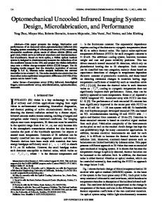
filtering operations that a user selects and can easily surpass the available processing power in the extreme cases of complex image processing operations. VI. R ESULTS As a result of the present paper, an integrated compact microscanning-endoscope prototype has been designed, assembled, and tested under operational conditions. In Fig. 5, the main GUI panel of the software is presented in the case of scanning a heart tissue in vitro. The left window refers to the raw images after a reconstruction, while the right one refers to the processed images after the application of user selectable filtering algorithms for the image enhancement. The field of view of the image presented was 11 × 11 mm2 with a resolution in the order of 50 µm, with its precise value depending on the design parameters of the collimating lens and the collecting fiber used. In Fig. 6, in vivo images of a finger tissue and part of a face are given. The resolution was 1024 × 1024 pixels with field of view of 12 × 10 mm and 80 × 80 mm, respectively. These images were reconstructed using the 650-nm channel with the laser power in the object plane measured on the order of 3 mW. These images were postprocessed by a grey-value equalization. Using the same setup, the imaging at longer object distances is possible as shown in the face image on the right. The part of the face shown was acquired at an object distance of about 500 mm. VII. C OMMENTS AND C ONCLUSION Compared to the existing commercial endoscopes, the present microscanning-endoscope device offers a number of advantages, among which, the most important is the increased resolution, which was found to be approximately 16 line pairs/mm. This performance has been achieved by using a laser-scanning technology for endoscope imaging and a novel data processing and control system. Due to the technology employed in the micromirrors fabrication, the endoscope head has proved to be robust to the common sterilization procedures that have been followed for surgical equipment without any noticeable deterioration of its optomechanical parts. The only limitations are the low dynamic range currently achieved (∼30 dB) together with the polarization destruction of the optical signals in the fibers employed for light delivery and collection. These limitations are expected to be faced with the use of advanced components in the optical illumination and detection parts realized. The supporting data-acquisition, control, and processing system ensures an enhanced signal handling and enables the microscanning-endoscope operation in real-time conditions. The multithreading technology was fully exploited to utilize the available processing power of the SMP system used. The overall software has been designed as an asynchronous eventdriven process capable of retaining the synchronization with the open-loop control scheme followed, while its modular architecture allowed an easy debugging and adaptation of the system during its development and testing phases. The dataacquisition, control, and processing system presented here acquires, reconstructs, stores, and displays color images with
Authorized licensed use limited to: IEEE Xplore. Downloaded on November 12, 2008 at 04:25 from IEEE Xplore. Restrictions apply.
PAPAGEORGAS et al.: IMAGING AND CONTROL SYSTEM MICROMIRROR LASER-SCANNING ENDOSCOPE DEVICE
Fig. 4.
1731
Flowchart of the multithreading software developed.
resolutions of at least 500 × 500 pixels and at rates up to 20 frames/sec. In addition, it generates the control waveforms for the scanning micromirrors and postprocesses and displays the collected images in a second window of the GUI’s main panel in real time. The multithreading technologies supported in the new Microsoft Windows operating systems, combined with the SMP Intel Architecture for PCs, have provided the necessary computing power and versatility for the implementation of the system described. What is important with the proposed DACP
system is that the methodology followed ensures scalable and continuous in the time performance improvement by taking advantage of the present and future Pentium processor advances (as the hyper-threading and dual core technologies) and the evolution of the open PC platform architecture for symmetric parallel processing. The proposed data-acquisition-software development methodology combines the multithreading technology with the PC SMP architecture and a standard dataacquisition board, resulting in an image acquisition and control system with a deterministic behavior to critical events and
Authorized licensed use limited to: IEEE Xplore. Downloaded on November 12, 2008 at 04:25 from IEEE Xplore. Restrictions apply.
1732
IEEE TRANSACTIONS ON INSTRUMENTATION AND MEASUREMENT, VOL. 55, NO. 5, OCTOBER 2006
Fig. 5. Main panel of the GUI developed, showing part of a heart tissue (in vitro). The left window displays a raw input image, whereas the right window presents a processed version of the input image.
Fig. 6. In vivo image of a finger tissue and part of a face. The resolution was 1024 × 1024 pixels with field of view of 12 × 10 mm and 80 × 80 mm, respectively. The part of the face shown on the right was acquired at an object distance of about 500 mm.
scalable real-time performance. The methodology and technologies used can be properly adapted and applied in the development of a sophisticated image processing and control software for laser-scanning imaging systems. R EFERENCES [1] T. Lange, “State of the art of video techniques for endoscopic surgery,” Endosc. Surg. Allied Technol., vol. 1, no. 1, pp. 29–35, 1993. [2] A. Cuschieri, G. Buess, and J. Perissat, Operative Manual of Endoscopic Surgery, vol. 1/2. Heidelberg, Germany: Springer-Verlag, 1992/1994. [3] D. Dickensheets, “MOEMS-based instruments for in-situ scanning confocal microscopy,” in Proc. 14th Annu. Meeting IEEE LEOS, Nov. 12–13, 2001, vol. 1, pp. 68–69. [4] W. Piyawattanametha, H. Toshiyoshi, J. LaCosse, and M. C. Wu, “Surface-micromachined confocal scanning optical microscope,” in Proc. CLEO, May 2000, pp. 447–448. [5] Electronic Light Microscopy, Techniques in Modern Biomedical Microscopy, D. Shotton, Ed. New York: Wiley-Liss, 1993, ch. 12. ISBN Y-0-471-56077-4. [6] K. E. Petersen, “Silicon torsional scanning mirror,” IBM J. Res. Develop., vol. 24, no. 5, pp. 631–637, Sep. 1980. [7] D. L. Dickensheets and G. S. Kino, “Silicon-micromachined scanning confocal optical microscope,” J. Microelectromech. Syst., vol. 7, no. 1, pp. 38–47, Mar. 1998. [8] U. Hofmann, S. Muehlmann, M. Witt, K. Dörschel, R. Schütz, and B. Wagner, “Electrostatically driven micromirrors for a miniaturized confocal laser scanning microscope,” in Proc. SPIE—Conf. Miniaturized Systems With Micro-Optics and MEMS, Santa Clara, CA, 1999, vol. 3878, pp. 29–38.
[9] M. Herrig, U. Neubert, and W. Muller, Micromechanischer LaserscannerApplikation im Funktionmuster eines Laser-Scan-Mikroskops fur die Medizin, 1992. VDI-Berichte, Band 960, S. 671-674 Dusseldorf, Germany. [10] P. Papageorgas, D. Maroulis, H. Albrecht, B. Wagner, G. Anagnostopoulos, M. Schurr, N. Theofanous, P. Dario, and C. Depeursinge, “The data-acquisition, processing and control system of a micromirror-based laser-scanning endoscope,” in Proc. ICECS, 2002, pp. 1203–1206. [11] G. Anagnostopoulos, B. Wagner, P. Papageorgas, U. Hofmann, D. Maroulis, and N. Theofanous, “The electronics of a control system for micromirrors in a laser-scanning device,” in Proc. ICECS, 2002, pp. 1207–1210. [12] T. A. Pologruto, B. L. Sabatini, and K. Svoboda. (2003, May 17). “ScanImage: Flexible software for operating laser scanning microscopes,” BioMedical Engineering OnLine. [Online]. Available: http://www.biomedical-engineering-online.com/ [13] D. M. Rector, D. M. Ranken, and J. S. George, “High-performance confocal system for microscopic or endoscopic applications,” Methods, vol. 30, no. 1, pp. 16–27, May 2003. [14] J. Rakesh, Predictability vs. Gurantee Under Windows NT, Foster, CA: California Software Laboratories. [Online]. Available: http://www. cswl.com/whiteppr/tech/predict.html [15] S. Dekey, Making Windows NT a Real-Time Solution—A Technical Overview, Austin, TX: National Instruments Co. [Online]. Available: http://www.ni.com [16] R. Cutler and L. Davis, Developing Real-Time Computer Vision Applications for Intel Pentium III based Windows NT Workstations. [Online]. Available: http://www.cs.umd.edu/~rgc/pub/frame99 [17] Performance Improvements on Intel Architecture Based Multiprocessor Workstations: Multithreaded Applications Using OpenMP, Santa Clara, CA: Intel Co. [Online]. Available: http://www.intel.com [18] A. Binstock, “Multithreading, hyper-threading, multiprocessing: Now what’s the difference?” Pacific Data Works, LLC, Intel Developer Services. [Online]. Available: http://cedar.intel.com/cgi-bin/ids.dll/ content/printable.jsp [19] Multi-Threading: Taking Advantage of Intel Architecture Multiprocessor Workstations, 1999. Version 1.0 Initial Release Intel Corp..
Panagiotis G. Papageorgas received the B.Sc. degree in physics and the Ph.D. degree in applied physics from University of Athens, Athens, Greece, in 1984 and 1995, respectively. From 1985 to 1991, he worked as a Teaching Assistant with Doctoral Fellowship in the Laboratories of Electronics and Meteorology of the Department of Applied Physics, University of Athens. From 1988 to the present, he has been a Professor of digital electronics with the Military School of Telecommunications and Electronics. Since 1994, he has been working as a Researcher with the Department of Informatics and Telecommunications of the same University, in European projects for biomedical applications and the development of electronic instrumentation for air-pollution monitoring. He is currently working as an Associate Professor with the Department of Electronics, Technological Education Institute of Piraeus, Athens.
Dimitris Maroulis received the B.Sc. degree in physics, the M.Sc. degree in radioelectricity, the M.Sc. degree in cybernetics, and the Ph.D. degree in informatics, all from University of Athens, Athens, Greece, in 1973, 1977, 1980, and 1990, respectively. In 1991, he was elected as a Lecturer, and in 1994, he was elected as an Assistant Professor with the Department of Informatics of the same university. He is currently working in the same Department in teaching and research activities, including projects with the European community. His main areas of activity include data-acquisition systems, real-time systems, image analysis, and biomedical systems.
Authorized licensed use limited to: IEEE Xplore. Downloaded on November 12, 2008 at 04:25 from IEEE Xplore. Restrictions apply.
PAPAGEORGAS et al.: IMAGING AND CONTROL SYSTEM MICROMIRROR LASER-SCANNING ENDOSCOPE DEVICE
Giorgos Anagnostopoulos received the Diploma in electrical and computer engineering from the University of Patras, Patras, Greece, in 1998. From 1998 to 2000, he was a Researcher in the area of electronic instrumentation for biomedical applications, working with the optoelectronics group in the Division of Communications and Signal Processing, Department of Informatics, University of Athens, Athens, Greece. Since 2001, he has been a cofounder and Vice President of Alma Technologies SA, Athens, a silicon intellectual property cores startup, serving in the field of image and video compression. Mr. Anagnostopoulos received an award from the Technical Chamber of Greece for his final year thesis “Design and implementation of a NIC for a Wireless LAN transceiver at 2.4 GHz” in 1998.
Hansjörg Albrecht was born in Stuttgart, Germany, in 1942. He received the B.Sc. degree in physics from Stuttgart University in 1969 and the Ph.D. degree in 1976 from Hamburg University, Hamburg, Germany. From 1969 to 1971, he worked as the Development Engineer in AEG-Telefunken, Berlin, Germany, and from 1971 to 1978, he worked as a Scientist with the Central Institute for Biomedical Engineering, Erlangen-Nuremberg University, Erlangen, Germany. From 1978 to 1983, he worked as a Scientist with DFVLR, and from 1984 to 1989, he was the Head of the product management monitoring with Dräger AG, Lübeck, Germany. From 1989 to 1990, he was a Scientific Adviser with the Laser-Medizin-Zentrum (LMZ), Berlin, where he was the Head of the Physicochemical Technologies Department. Since 1990, he has been the Managing Director of LMZ, Berlin, which was reorganized in 1995 into LMTB.
Bernd Wagner received the physics diploma and the Ph.D. degree from University of Mainz, Mainz, Germany in 1982 and 1986, respectively. He joined Fraunhofer-Institute for Silicon Technology (ISIT) Itzehoe, Germany, working on design, technology, and application development of microsystems. He is currently the Head of the Microsystems/MEMS Department, Fraunhofer ISIT. His current research activities are focused on siliconbased sensors and actuators, optical microsystems, and RF-MEMS. He has authored or coauthored over 80 scientific publications.
1733
Dimitris K. Iakovidis received the B.Sc. degree in physics, the M.Sc. degree in cybernetics (with honors), and the Ph.D. degree from the Department of Informatics and Telecommunications, University of Athens, Athens, Greece, in April 2001 and February 2004, respectively. He has coauthored more than 30 papers on biomedical applications and image analysis, and he is a regular reviewer for many international journals. He is currently working as a Research Fellow in the same department. His research interests include biomedical systems, image analysis, pattern recognition, and bioinformatics.
Nikiforos G. Theofanous was born in Ioannina, Greece, in 1940. He received the B.Sc. degree in physics, the M.S. degree in radioelectricity, the Ph.D. degree in physics, and the M.Sc. degree in electronic automation, all from University of Athens, Athens, Greece, in 1964, 1971, 1973, and 1975, respectively. In 1969, he was appointed as an Assistant, and in 1973, he was elected the Chief Assistant of the electronics laboratory, University of Athens, for the period up to 1981. In 1982, he was elected as a Lecturer and, in 1984, an Assistant Professor with the Department of Physics, University of Athens. In 1990, he was transferred to the Department of Informatics of the same university, where in 1991, he was elected as Associate Professor and, in 1995, as a Full Professor in electronics and optoelectronics. He is currently working in the above department in teaching and research activities, including projects with the European community. His main areas of activity include electrooptics, fiber optics, and optoelectronics with applications in optical communications and in optoelectronic biomedical systems. Dr. Theofanous is the President of the Greek Laser and Electrooptics Scientific Society.
Authorized licensed use limited to: IEEE Xplore. Downloaded on November 12, 2008 at 04:25 from IEEE Xplore. Restrictions apply.