AbstractâThis paper introduces a high-speed and low power multi-match priority encoder design applicable in many com- puter and networking systems.
A High-Performance Multi-Match Priority Encoder for TCAM-Based Packet Classifiers Miad Faezipour and Mehrdad Nourani Center for Integrated Circuits & Systems The University of Texas at Dallas, Richardson, TX 75083 {mxf042000,nourani}@utdallas.edu Clk r EN
Abstract— This paper introduces a high-speed and low power multi-match priority encoder design applicable in many computer and networking systems. We propose a scalable multimatch prioritizer logic circuitry that can successively find all or the first r matched inputs in a set. The design is well suited for multi-match packet classification tasks that utilize content addressable memories as the search engine. We use a data partitioning scheme to efficiently reorganize input data for further performance improvement. A VLSI implementation of our design in 0.18μm technology can achieve speed that outperforms the conventional multi-match packet classifier design by more than an order of magnitude. Overall power consumption is reduced by more than 40% using innovative partitioning which limits the search to a small portion of TCAM cells.
I. I NTRODUCTION Priority-based operations are fundamental to a variety of basic digital components such as incrementers/decrementers and comparators. From networking perspective, they are widely used in packet forwarding and packet classification as well. A Priority Encoder (PE) circuit encodes the address (index) of the highest priority input. The operation is performed by passing a priority token from the highest priority bit (input) to the lowest. Performance of PEs are critical, as they are integrated within many digital systems. As the number of inputs scales up, high-speed and low power PE circuits are essential in order to achieve high-performance systems. High-speed and power efficient CMOS PE circuits have been introduced in [1][2][3]. Multi-level folding and parallel priority look ahead techniques were the key novelties used in these designs. In general, packet classification refers to finding the best matching filter containing multiple fields among the filter (also called rule in the literature) set for a given packet. The standard five-tuple fields include the source address, destination address, protocol, source port and destination port [4]. Ternary Content Addressable Memories (TCAMs) are well suited for performing high speed parallel searches on database with ternary entries, since they provide the match results with deterministic throughput (i.e. one search per cycle) and deterministic capacity. TCAMs inherently include the priority encoder, resulting in the highest priority match. Hence, TCAM has become quite popular for packet classification [4][5]. Multi-priority encoding is used in a number of new emerging networking systems. One main application of multipriority encoding is multi-match packet classification using Ternary CAM devices. Network Intrusion Detection Systems (NIDS), load balancers, and programmable network elements (PNE) require finding all or the first few matching filters in packet classification [6]. Regev et al. introduced logic circuit designs that utilize multiple single priority encoders to find 978-1-4244-1680-6/07/$25.00 ©2007 IEEE
Multi-Match Priority Encoder m n-1
Search Key
. . .
TCAM Words
Figure 1.
EPn-1
MPZ
. . .
m1
EP1
m0
EP0
E n c o d e r
log n 2 Index
Conceptual block diagram of the design.
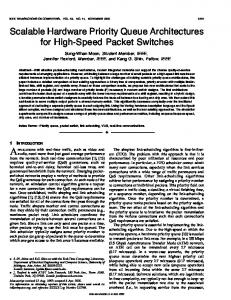
matching addresses successively [7][8]. Nowadays, gigabit rates are required for networking applications. Therefore, developing high-speed and low-power multi-priority encoder circuits are design concerns as well. While TCAMs perform packet classification at high speed, they cannot directly report all possible matches in a database. This is due to the native structure of a TCAM cell design, which consists of a conventional priority encoder, resulting in the highest priority match. We propose a multi-matching packet classifier by modifying the prioritizer circuit in conventional TCAM units. II. M ULTI -M ATCH P RIORITY E NCODING A TCAM cell includes the TCAM word and a PE unit. The PE unit itself consists of a prioritizer circuit and a conventional address encoder. A valid log2 n-bit address out of the encoder is generated only if at most one of its n inputs is high at a time. The main idea is to modify the single-match prioritizer unit to a Multi-match Prioritizer (MPZ), as shown in Figure 1, so that the encoder would generate all matching indices, one at a time. An 8-bit power optimized priority encoder cell is used as our reference model for the single-match prioritizer (PZ) unit [1]. We have designed and implemented the transistor level schematic of this prioritizer circuit shown in Figure 2. The logic equation for the PZ circuit (using boolean notations) is: i−1
EPi = en · ( ∏ Dk ) · Di ,
0 ≤ i ≤ n−1
(1)
k=0
Equation 1 indicates that the PZ circuit has n inputs and n outputs where EPi denotes the ith output, Di ’s are the input lines and en is the enable line. In the PZ circuit, only one chain of the evaluate transistors will discharge during evaluation. The transistor count of the circuit is 62, and the necessary precharge nodes are very few. We use this circuit as the basic (single) prioritizer unit. It is also highly power efficient compared to other priority encoder configurations using multilevel look-ahead structures [2][3]. A. Multi-Match Prioritizer Unit We add a control logic circuitry to the prioritizer circuit to report all matches in a prioritized sequence. The MPZ
Clk
EN
r[2:0]
EP7
Comparator
c[2:0]
D7 c[2:0]
en
s m n-1
m n-1
EPn-1
M n-1
.. .
m n-1
Clk
s
Counter
EP6 D6
EP5
.. .
D5
.. .
EPn-2
.. .
s EP4
m2
D4
m2
m2
.. .
M2
EP2
Prioritizer s EP3
m1
D3
m1
m1
M1
EP1
M0
EP0
s EP2
m0
m0
D2
EP1
ep0
Q D
D1 Clk
.. .
OE
ep1
EP0
Q D
D0 Clk
ep2 en
Q D Clk
Clock
ep n-2
.. . Q D
Clk
Figure 2.
The reference 8-bit power-optimized prioritizer circuit.
circuit, shown in Figure 3, functions in response to a counter which counts from 0 to n, where n is the highest possible number of matches. In other words, n can be assumed as the number of inputs in the worst case. On the first clock cycle, the MPZ should function as a single-prioritizer unit, reporting the highest priority match. On the next clock cycle the next highest priority match should be provided at the output. This procedure should be followed for all other clock cycles until the counter has reached counting up to n. In each clock cycle, a function of the original inputs and the higher priority outputs of the prioritizer circuit in the previous clock cycle should be fed through the prioritizer circuit. Let mi denote the original input lines (i.e. match lines from TCAM words), epi denote the EPi outputs of the prioritizer after one clock cycle, Mi be the set of inputs that should be given to the prioritizer circuit, and EN be the enable line. The logic equations for the MPZ circuit can be derived as: i−1
Mi = s · mi + s · (mi · ∑ epk ) , i−1
0 ≤ i ≤ n−1
(2)
k=0
EPi = EN · ( ∏ Mk ) · Mi ,
0 ≤ i ≤ n−1
(3)
k=0
Signal s is the select line of the multiplexers that control which data should be chosen for the corresponding Mi . This select line should be low for the first clock cycle and high for the rest. Thus, s can be implemented by simply ORing all the log n−1 ck . The MPZ unit functions counter outputs ci : s = ∑k=02 in an efficient manner; in essence it reports all r matches in exactly r-cycles. This implies that in case of the need to report the first r matches instead of all possible matches, a comparator unit could be added to the MPZ design wherein the count value c and the r value are compared. Once the count exceeds r, the enable line EN is set to zero; hence disabling the MPZ unit. As authors in [9] stated, the maximum degree of matches (number of matches) often requested in real-world access
Figure 3.
The MPZ architectural design
control list (ACL) filter database is statistically around 8. Considering this fact the counter used in any MPZ unit can be designed to count up until 8. This implies that only log2 8 = 3 lines are required for the counter. In addition, the comparator can be designed to compare the count value and r = 8. B. Scalability To achieve a modular design with cascaded blocks we define an output enable (OE) line which indicates when all the matches have been provided at the output. This signal is activated when all the matching results have been provided at the output, and deactivated when any match is found at the output. The OE signal also highly depends on the EN line. The OE line in a MPZ can be expressed as follows: n−1
OE = EN · ∏ EPi
(4)
i=0
Figure 4 shows the concept of cascading eight, 8-bit MPZ modules to design a 64-bit MPZ. By connecting the OE line of each stage to the EN (enable line) of the next stage (in this case higher priority stages are placed at the left), we assure that each block would be enabled only if all the higher priority blocks have completed reporting their matches at the output. The cascaded design would have at most two additional clock cycle delays for each mismatching MPZ unit. Hence, if all matches are concentrated within one block of MPZ, a high throughput can be achieved. Another scalable design for the MPZ is based on the concept of parallelism. A parallel architecture similar to the parallel priority look-ahead technique [1] is shown in Figure 5. In case of 64-bit multi-match design, the first stage MPZ unit should have a clock period of at least 8 times slower than the 8 MPZ units in the second stage. This is due to the fact the first stage should be enabled for at least 8-cycles, to allow the second stage MPZ to report all the results.
m[7:0]
m[15:8]
m[23:16]
m[63:56]
"1" EN
OE
MPZ1
EP[7:0]
Figure 4.
EN
OE
EN
MPZ2
OE
EN
MPZ3
EP[15:8]
OE
MPZ8
EP[23:16]
EP[63:56]
Cascaded MPZ architecture for a 64-bit design. Clk m[63:56]
m[63:56]
m[55:48]
D7
EP7
D6
EP6
D5
EP5
Clk m[47:40]
MPZ6
EP[47:40]
Clk m[39:32]
MPZ5
EP[39:32]
EN
D4
MPZ
D3
EP4
Clk m[31:24]
EP3
MPZ4
EP[31:24]
EN
m[31:24]
D2
EP2
D1
EP1
D0
EP0
Clk’
Clk m[23:16]
MPZ3
EP[23:16]
EN Clk m[15:8]
m[15:8]
MPZ2
EP[15:8]
EN Clk m[7:0]
Figure 5.
EP[55:48]
EN
m[39:32]
m[7:0]
MPZ7 EN
TClk’=8TClk
m[23:16]
EP[63:56]
EN Clk m[55:48]
m[47:40]
MPZ8
MPZ1
EP[7:0]
EN
Parallel MPZ architecture for a 64-bit design.
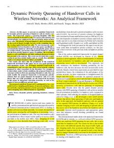
The parallel architecture has a better speed for singlematch applications (when assuming TClk� = TClk ) and multimatches concentrated in one MPZ unit, while the cascaded configuration is observed to be more efficient in terms of both speed and area for uniformly distributed multi-matching tasks. Area is another concern for the two scalable configurations. The parallel architecture would have an additional MPZ unit plus a few OR gates, compared to the cascaded architecture. The above discussion indicates that performance in large filter sets highly depends on the locations of the matches. To achieve best timing results, the input data filters should be relocated intelligently. This issue follows next. III. P ERFORMANCE /P OWER I MPROVEMENT Intersection among filters in the database mainly results in multiple matches. Therefore, partitioning the filter set based on filter intersections, and performing the TCAM search on a partition, can significantly improve the performance. From the MPZ design, we have seen that by having all matches concentrated within one block, the multi-match performance can achieve the highest extreme in performance; in other words it is capable of finding r matches in r cycles. The data partitioning scheme partitions the filters in the database such that each partition would hold the maximum number of intersections among its filters. In addition, partitions will be disjoint, i.e. any pair of partitions do not have any overlap in the filters that they contain. Since there would
always be a number of filters that do not have any intersection with any other filter, one last partition is needed in which all these distinct filters can be placed. We define the term distance for any two filters fi [w − 1 : 0] and f j [w − 1 : 0] of w-bits wide to be the summation of the bit-wise comparisons. In this definition, a don’t care in any bit position would result in zero distance for that particular bit position. So, for example filters 0110111x and 01x0xx11 have zero distance, since the result of comparison in each bit position yield zero distance. However, filters 0110110x and 01x0xx11 do not have zero distance, since their values differ in bit position w = 1. Our partitioning heuristic is to place all zero distance filters within one partition. Figure 6 (a) illustrates an example of a small filter set of 10 filters partitioned based on maximum intersections. Filters are assumed to be 8-bits long for simplicity. Filters 1, 4, and 10 have zero distance, hence they can form one partition; P1 . Also, filters 8 and 9 have zero distance with filter 10, therefore they are also placed in P1 . Filters 5 and 6 make a zero distance with filter 2, and form partition P2 . Finally, filters 3 and 7 that have no zero distance with any other filters, form the distinct filter collection, and are placed in a separate partition (P3 ). In this example, if ”11010010” arrives as the search key, partition P1 would be chosen and the search is performed on a relatively small TCAM containing partition P1 only. Our data partitioning would ensure that all possible matches for a given packet are located in one partition. Figure 6 (b) illustrates the partitioning approach used with the MPZ architecture. Note that the last partition (PN p ) does not need a MPZ unit since it would result in at most one match. The MPZ and encoder circuit connected to the TCAM provide the addresses of the r matches in at most r cycles successively. Since the maximum number of multiple matches is around 8 [9], no larger than 8-bit MPZ units is required. Additionally, this approach does not add any extra filter to the whole set, unlike others, e.g. the SSA scheme [10], that adds new filters for partially overlapping filters in each partition. This feature makes the our approach much more memory efficient. Moreover, performing the TCAM search on only a small portion of the entire database can significantly save power consumption due to the frequently charging and discharging of the highly capacitive match line. To achieve such power savings, a Selector Unit is required so that the search mechanism would result in enabling the TCAM search on one partition, while disabling others. The selector unit is a small TCAM unit that stores a common code for the filters of each partition. More description on the selector design can be found in [11]. IV. E XPERIMENTAL R ESULTS A. Simulation of MPZ Unit An 8-bit MPZ unit was implemented using Synopsys tools [12]. Timing simulations are shown in Figure 7. The MPZ inputs m[7 : 0] =”01011000” are assumed to be the TCAM output match lines. Output results EP[7 : 0] were observed to be ”00001000” (08H), ”00010000” (10H) and ”01000000” (40H) on the first three clock cycles, respectively. Figure
TABLE I S IMULATION R ESULTS FOR n- BIT MPZ U NITS
Before Partitioning After Partitioning Partition P1 1) 1101xx10 4) 11x1xxxx 10)1x01xx10 8) 100x1xx0 9) 1001x110
Filters: 1) 1101xx10 2) 0xx01110 3) 1011001x 4) 11x1xxxx 5) 00101xx0 6) 0110x1x0 7) 0111x010 8) 100x1xx0 9) 1001x110 10)1x01xx10
Partition P2 2) 0xx01110 5) 00101xx0 6) 0110x1x0 Partition P3
Figure 6.
Search Key
TCAM
Selector
Partition P2 (f2, f5, f6)
MPZ +
Index
Encoder
MPZ +
Index
Encoder
n 8 16 32 64
Delay [ns] 9.92 17.92 25.09 43.87
Area [NAND] 206 437 769 1373
Speedup Sn 40.32 44.64 63.77 72.94
TABLE II P OWER S AVINGS TCAM
3) 1011001x 7) 0111x010
(a) Partitioning
TCAM
Partition P1 (f1, f4, f10, f8, f9)
Partition PNp
Encoder
|P|max 12 8 4
Index
(f3, f7)
(b) The classifier engine.
|P|min 4245 4225 4090
ΔEmax 99.76% 99.84% 99.92%
ΔEmin 15.1% 15.5% 18.2%
Application of data partitioning to a small example.
Figure 7.
Timing simulation for an 8-bit MPZ unit
7 indicates that the MPZ unit can work with Tclk = 10ns ( fclk = 100MHz). Assuming the minimum length of 40 bytes per packet, MPZ can achieve throughput of 40 × 8 × 108 = 32Gbps. B. Speedup The maximum throughput of a single MPZ unit would be the smallest clock period for the circuit to function correctly. Table I compares the statistics for four n-bit MPZ units that we have implemented. As n grows, the delay and the cost of MPZ both increases. However, note carefully that growth of critical path delay, shown in the second column, is not an indication of improvement. To be more clear about this the third column shows the estimated speedup (Sn ) in each case compared to a software-based classification approach. We assumed that the host running the classification software needs at least one memory access and one comparison instructions r·n·(tmem +tcmp ) , where per entry. This yields speed up of: Sn ≥ r·TClk n tmem and tcmp refer to the corresponding instructions, and TClk n is the duration of the clock driving a n-bit MPZ. Obviously, TClk n should be larger than the delay values given in Table I. Note that in practical cases r