This article has been accepted for publication in a future issue of this journal, but has not been fully edited. Content may change prior to final publication. Citation information: DOI 10.1109/ACCESS.2017.2698098, IEEE Access
LTE-Railway User Priority-based Cooperative Resource Allocation Schemes for Coexisting Public Safety and Railway Networks I. Ahmad, W. Chen, and K.H. Chang
Abstract— This paper addresses the issues of resource allocation and co-channel interference management for coexistence of and cooperation between two long term evolution (LTE) networks. In the Republic of Korea, the LTE-based public safety (PS-LTE) network is being built for the 700 MHz frequency band. However, the same band is also allocated to the LTE-based high-speed railway (LTE-R) network, so immense interest and useful researches into co-channel interference management schemes are immediately needed. In this paper, we focus on the downlink (DL) system of coexisting PS-LTE and LTE-R networks by considering LTE-R radio access network (RAN) sharing and non–RAN sharing by PS-LTE users equipment (UEs) to analyze co-channel interference. We also utilize cooperative communications schemes, such as coordinated multipoint (CoMP) and inter-cell interference coordination (ICIC) in order to resolve the problem of co-channel interference. We categorize the coexistence of PS-LTE and LTER networks into five different scenarios, and evaluate the performance of each scenario based on various performance indexes, such as user equipment (UE) average throughput, UE received interference, and UE outage probability. Moreover, users can achieve high throughput as well as obtain a better channel condition by using RAN sharing. In addition, we always provide the higher priority to railway user while allocating the resources for coexisting public safety and railway networks using LTE-R RAN sharing by PS-LTE UEs because train control signal (LTER-UE) needs more reliable communication as well as low latency in order to fulfil its mission-critical service (MCS) demands. By employing coordinated scheduling (CS) CoMP, the highest throughput performance can be attained with RAN sharing. Furthermore, dynamic ICIC enhances cell-edge UE performance and reduces UE received interference, as well as the outage probability, by using the partial reuse band and bonus band allocation. Index Terms—PS-LTE, LTE-R, Coexistence, CS CoMP, Dynamic ICIC
I. INTRODUCTION In the Republic of Korea, the national disaster safety network, which costs over 1.6 billion US dollars, has been deployed since 2015 and is being built using LTE in 700 MHz frequency band [1]. However, the same band is also allocated to the LTE-R network and to the e-navigation network over marine environments. I. Ahmad, C. Wan, and K.H. Chang are with the Department of Electronic Engineering, Inha University, Korea (e-mail:
[email protected],
[email protected], and
[email protected]). Corresponding Author: KyungHi Chang (
[email protected]) English revised by NURISCO (http://www.nurisco.net).
As representative railway communications, the global system for mobile railway (GSM-R) is the most widely used standard, particularly in Europe. GSM-R is a unique standard for an integrated wireless railway communications system, and its stability has been proven for more than 10 years. However, due to its limited transmission capacity, LTE-R is taken into account as the emerging system for the current GSM-R in highspeed railway scenario, not only for its practical benefits and improved performance, but also owing to the present development of public telecommunications systems [2]. It is well aware that main users of the public safety network are police, firefighters, etc., and railway network will be the communications services provider for both control trains and train crews. Since railway communications, together with train control, has been critical for the reliability and safety of railway operations, if public safety and railway networks utilize the same frequency band. Hence, there is a dire need of great interest and useful researches into co-channel interference management. The major issue for the 700 MHz systems is co-channel interference from the coexistence of the PS-LTE and LTE-R networks. To address this interference problem and to enhance the channel conditions for LTE-R control signal transmissions, cooperative communications schemes, such as CS CoMP and dynamic ICIC, can be employed. In a CoMP cooperating set (defined below), the transmission points can cooperate in scheduling decisions and data transmissions to mitigate the interfering signal, and thus improve the UE signal to interference-plus-noise ratio (SINR), especially around cell edges. The PS-LTE evolved nodeBs (eNBs) and LTE-R eNBs participate in a CoMP cooperating set based on a signal-tointerference ratio (SIR) threshold, and thus, by changing the threshold, the number of participating eNBs will vary in a CoMP cooperating set. Two main categories of CoMP schemes are discussed in the technical report [3], such as joint processing (JP) and coordinated scheduling. Although JP might have more throughput gain than CS but it has high implementation complexity due to the requirement for data availability in all participating base stations (BSs) of the CoMP cooperating set, which makes the scheme unsuitable for CoMP with non-ideal backhaul [3]. Thus, in this paper, we consider CS as the baseline cooperating scheme from a practical perspective. In CS, the availability of user data is at the serving PS-LTE eNBs or LTER eNBs, but scheduling decisions need to be shared between the cooperating BSs to minimize interference among the UEs.
Page 1 of 15
2169-3536 (c) 2016 IEEE. Translations and content mining are permitted for academic research only. Personal use is also permitted, but republication/redistribution requires IEEE permission. See http://www.ieee.org/publications_standards/publications/rights/index.html for more information.
This article has been accepted for publication in a future issue of this journal, but has not been fully edited. Content may change prior to final publication. Citation information: DOI 10.1109/ACCESS.2017.2698098, IEEE Access
A. Related work Most prior works on the LTE-R network are related to channel model analysis with a simple LTE-R network layout [4, 5]. Moreover, complex scenarios like the coexistence of public safety and railway networks has been considered in our previous work [6]. However, the coexistence of two LTE networks creates several challenges to be resolved (e.g., cochannel interference, and service prioritization, etc.). So, there is dire need of great interest and useful researches into cochannel interference management. In the existing literature various techniques have been considered to resolve the cochannel interference problem, including interference alignment and channel diagonalization through a two-step precoder process for multi-user CoMP [7], power control scheme [8], and interference management in 3GPP LTE-A [9]. Among all the previously proposed schemes [6-9], it has been noticed that cooperation between eNBs provides more benefits in terms of quality of service (QoS), fairness, and load balancing, but at the cost of a little increase in feedback complexity in terms of sharing channel state information (CSI). In our previous work [6], we employed enhanced ICIC (eICIC) and further eICIC (FeICIC) along with CS CoMP under the RAN sharing case for offloading more public safety users to the railway network but CS CoMP was only considered among the LTE-R eNBs. In this paper, we consider CS CoMP and dynamic ICIC as candidates for interference management for coexisting public safety and railway networks. Unlike reference [6], in this paper, the CS CoMP is considered between PS-LTE and LTE-R eNBs, PSLTE and PS-LTE eNBs, and LTE-R and LTE-R eNBs. Moreover, we categorize the coexisting public safety and railway networks into five diverse scenarios where CS CoMP is employed for LTE-R RAN sharing and non-RAN sharing by PS-LTE UEs. Similarly, many researches investigated the problem of radio resource management, for example, an interference-aware resource-sharing scheme [10], joint scheduling mechanism [11], and game-based resource allocation [12]. However, they mostly focused on optimizing system throughput and efficiency by independently considering the resource allocation problem. They did not consider user priority situations while allocating the resources, and they also ignored the mission-critical service (MCS) demands of the user. In this paper, we consider the users’ service priority in order to fulfil its MCS requirements and also assess the cooperative communication schemes while applying realistic conditions using the wireless world initiative new radio (WINNER II) channel model [13], channel quality indicator (CQI), feedback and resource scheduling procedures. B. Contributions and Organization of the Paper In this paper, we investigate the co-channel interference problem between public safety users and railway user (downlink transmission of train control signals) for coexisting public safety and railway networks. RAN sharing is currently considered one candidate for coexisting public safety and railway networks which are utilizing the same frequency band, so active RAN sharing is considered [14] in this paper. Generally, the LTE-R eNBs are positioned within 20 m of the
railway track, so LTE-R UE receives a strong DL desired signal from LTE-R eNBs. Based on the hypothesis of more reliable railway network deployment, we solely employ LTE-R RAN sharing by PS-LTE UEs. Our work has three main focal points. First, we investigate the benefits of RAN sharing for the coexistence of two LTE networks by comparing RAN sharing and non-RAN sharing scenarios. Second, we always provide the higher priority to the railway user while allocating the resources using the LTE-R RAN sharing by PS-LTE UEs because train control signal (LTE-R-UE) needs more reliable communication as well as low latency in order to fulfil its MCS demands. And third, we employ cooperative and interference coordination schemes like CS CoMP [15] and dynamic ICIC [16] in order to reduce the interference issue for coexisting public safety and railway networks. In 3GPP LTE Rel. 8, ICIC was proposed, by which the centrally located users can use entire range of resource blocks; but for cell-edge users, the neighbor two eNBs cannot utilize the same set of resource blocks. In this regard, fractional frequency reuse (FFR) [17] was proposed; by which frequency reuse factor of three will be an example. This kind of network planning can mitigate the cochannel interference for the coexisting public safety and railway networks by proper management of frequency band among the PS-LTE and LTE-R eNBs. In 3GPP LTE Rel. 10, DL CoMP comprises the coordination between different cells. To support the inter-eNB coordination, the eNBs can communicate via X2 interface to share the scheduling information and can optimize the throughput of the cell-edge users. In this papers, public safety and railway eNBs are assumed to be in one CoMP cooperating set, and single centralized scheduler mutually process the information based on predefined rules: (a) always schedule the best resources to LTE-R UE, and (b) whenever the railway user needs CoMP support, other eNBs would stop scheduling resources that have already been taken by LTE-R UEs. Thus, CS CoMP mitigates co-channel interference, which enhances system throughput and also provides good channel conditions for LTE-R cell edge UEs. Furthermore, the dynamic ICIC scheme can also provide greater benefits to cell-edge UEs by using dynamic FFR, which effectively assign the non-occupied center-zone frequency bands, i.e., bonus bandwidth (BBW), to cell-edge UEs according to their QoS demands [16]. Hence, dynamic ICIC scheme further reduces co-channel interference based on the hypotheses of dynamic allocation of BBW. It is important to note that LTE-R network can be developed in centralized-RAN architecture using cooperative interference cancellation schemes in future network (5G) telecommunication standards. Indeed, the railway eNBs in our scenario can be considered as a group of remote radio unit (RRUs) which are linked with one baseband unit (BBU), and the centralized coordinated scheduling algorithm can be executed in the BBU. The CS CoMP and dynamic ICIC can also be utilized in next generation (5G) ultra-dense network deployment. With these considerations, cooperative communication schemes are also very effective and can be employed to restrain the interference from macrocells to the small cells and vice versa.
Page 2 of 15
2169-3536 (c) 2016 IEEE. Translations and content mining are permitted for academic research only. Personal use is also permitted, but republication/redistribution requires IEEE permission. See http://www.ieee.org/publications_standards/publications/rights/index.html for more information.
This article has been accepted for publication in a future issue of this journal, but has not been fully edited. Content may change prior to final publication. Citation information: DOI 10.1109/ACCESS.2017.2698098, IEEE Access
sharing and non–RAN sharing are discussed in the following sections. The propagation loss of each link is calculated as the following general equation: G AntennaGain PathLoss Shadowing Fading
(1)
Path loss PL is calculated by considering the rural macro model provided in the 3GPP specifications [18]. The macro path loss model for a rural area based on 700 MHz is given as: PL = 69.55 + 26.16log10 f 13.82log10 Db 44.9 6.55log10 Db log L 4.78 log10 f 18.33log10 f 40.94 Fig. 1. PS-LTE and LTE-R network deployment layout.
The rest of the paper is organized as follows. Section II presents a cooperative communications system that includes channel and traffic models. Section III explains the LTE-R user priority–based cooperative communications schemes for the coexisting public safety and railway networks. In Section IV, the performance of the cooperative communication schemes is assessed using system-level simulations (SLS). Finally, Section V concludes the paper.
II. COOPERATIVE COMMUNICATIONS SYSTEM MODEL FOR COEXISTING PUBLIC SAFETY AND RAILWAY NETWORKS In this paper, a LTE DL system for coexisting public safety and railway networks is considered, where both public safety and railway eNBs utilize the entire system bandwidth (BW). The number of physical resource blocks (PRBs), b, are assigned to each user in the time and frequency grid. We deploy K-tier ( K 1) PS-LTE network that coexists with the LTE-R network, with M PS-LTE eNB sites ( M 7) consisting L hexagonal sectors ( LP 3) in each site, and N LTE-R eNB sites ( N 4) consisting L hexagonal sectors
( LR 2) in each site. Hence, C is the total number of PS-LTE and LTE-R cells (C 29) . We denote all the base stations, B PS _ eNB1, ..., M , R _ eNB1, ..., N , and denote all users (i.e., PS-LTE UE U M and LTE-R UE U N ) as U . We assume that the inter-site distance (ISD) between the M sites is 4 km and that the N sites have an ISD of 1 km. In K-tier network deployment, the center site of the PS-LTE is the region of interest (ROI), whereas others cause interference. The ROI consists of one PSLTE eNB, which overlaps four LTE-R eNBs, as shown in Fig. 1. In each sector, PS-LTE UEs are randomly deployed within the ROI in a constant distribution. So, it is probable that some UEs will be dropped into the LTE-R eNBs region. LTE-R eNBs have the ability to give access to the PS-LTE UE via active RAN sharing. The trade-offs from switching between RAN
2
(2)
where L is the distance between the BS and users, f is the frequency, and Db is the BS antenna height. The shadowing produced by obstacles between UE and BSs is designed by assuming log-normal distribution. The notion of a shadowing map suggested by Claussen for eight neighbors [19] is utilized, and an inter-site correlation value of 0.5 is considered [20]. Fast fading indicates quick fluctuation of the signal levels due to multipath communication. In this paper, fast fading is produced according to the D1 and D2a scenarios supported by Winner II [13] for public safety users with low mobility and railway user with high mobility, respectively. The 3D antenna patterns, given by horizontal and vertical cuts, are utilized for the eNB and are calculated as follows:
A( , ) min AV ( )v AH ( )H ,Am
(3)
A detailed explanation of the parameters used to calculate the antenna patterns is available elsewhere [20]. The abstraction of the physical layer refers to acquire block error rate (BLER) for single transport block using specific modulation and coding level for computing the user throughput. In LTE-Advanced, the fifteen CQI indexes are stated based on channel coding rate and modulation schemes [21]. In order to reduce the computation burden at SLS side, we just utilize the BLER curves acquired by link-level simulation using additive white Gaussian noise (AWGN) channel. To predict BLER using multipath fading channel, AWGN-equivalent SINR is needed, which is obtained by mutual information-based exponential SINR mapping (MIESM) [22]. In order to simulate usual network traffic as well as its loading situations, practical traffic models are utilized [23]. The users are distinguished in terms of their applications, for example, VoIP and video. In this paper, we consider the LTE protocol stack and bearer models [24] to completely apply the traffic models at a user level. Scheduling: The general proportional fair (PF) scheduler [25] equation is as follows:
Page 3 of 15
k arg max
Ri Ri
(4)
2169-3536 (c) 2016 IEEE. Translations and content mining are permitted for academic research only. Personal use is also permitted, but republication/redistribution requires IEEE permission. See http://www.ieee.org/publications_standards/publications/rights/index.html for more information.
This article has been accepted for publication in a future issue of this journal, but has not been fully edited. Content may change prior to final publication. Citation information: DOI 10.1109/ACCESS.2017.2698098, IEEE Access
Start Calculate the metric matrix for LTE-R UE.
metric
b,i0 n _ PRB1
=
spectral _ efficiencyb,i0 [bit / cu] n _ slots n _ symbols n _ subcarriers
Yes
average _ throughputi0
LTE-R UE has no more bits to receive ? No
Schedule the rest PSLTE UEs based on PF rules.
If any RB b has already been allocated ? No
end
Yes
metric(b,:) = -Infinite (Do not schedule RB b again.)
Find the index of the PRB with the best channel condition for LTE-R UE.
b arg max metricb ,i0 b
n _ PRB1
Allocate the PRB to LTE-R UE. Fig. 2. Flow chart of central controller 1.
where Ri is the instantaneous rate, and Ri the average rate for user i. LTE-R user priority–based resource allocation: The predefined rules are considered for scheduling in the case of railway network RAN sharing by public safety users. Since the DL transmission of a train control signal (LTE-R UE) needs more reliable communication and low latency, the policy is to always allocate the best resources to the railway user first. Hence, we provide the higher priority to the railway user while allocating the resources to satisfy its MCS demands based on central controller (CC) 1. Fig. 2 gives the details of the CC1 mechanism in which the scheduling procedure for railway eNBs offers RAN sharing to public safety users, while public safety eNB schedule the users according to general PF scheduling. A. Coordinated Scheduling for Cooperative Communications under PS-LTE and LTE-R Network Coexistence The 3GPP agreed upon four CoMP deployment scenarios, which include intra-site CoMP and inter-site CoMP scenarios [15]. In this paper, we simulate both intra-site CoMP and intersite CoMP among all the BSs, including PS-LTE and LTE-R eNBs. As for railway network, the movement of LTE-R UE is in the direction of railway track which is located between the LTE-R eNBs. So, LTE-R UE suffers greater interference power from neighbor public saftey and railway eNBs. In order to lessen this undesirable interference, CS CoMP is employed between the neighboring public safety and railway eNBs.
1) Formation of a CoMP Cooperating Set In 3GPP LTE, the CoMP is a set of eNBs, directly or indirectly joining in physical DL shared channel transmission to the user. The CoMP cooperating set consists of multiple transmission points (TPs), such as PS-LTE and LTE-R eNBs, which can be represented as: CCoMP _ set
PS _ eNBs , R _ eNBM 1 , ..., R _ eNBM
N
(5)
where PS _ eNBs represents the center eNB site of the PS-LTE network with index s. Here, the center PS-LTE eNB site and total N LTE-R eNB sites within the ROI are considered in the CoMP set. Hence, CCoMP _ set consists of active and non-active cells in the CoMP set. The maximum available number of cooperating base stations does not mean that all of these BSs will always cooperate. In order to decide the number of participating BSs, an SIR threshold metric is utilized. 2) CS CoMP Implementation and Feedback Requirements According to LTE Rel. 11 framework [15], in this paper, dynamic cooperative muting based CS CoMP is considered between the public safety and railway eNBs and single central scheduler [26] is used for PRBs allocation. Each eNBs identify the corresponding CoMP UE according to user feedback. CoMP assistance by coordinated link. Unlike the cell-specific muting considered elsewhere [27-28], in this paper we apply the PRB-specific muting.
Page 4 of 15
2169-3536 (c) 2016 IEEE. Translations and content mining are permitted for academic research only. Personal use is also permitted, but republication/redistribution requires IEEE permission. See http://www.ieee.org/publications_standards/publications/rights/index.html for more information.
This article has been accepted for publication in a future issue of this journal, but has not been fully edited. Content may change prior to final publication. Citation information: DOI 10.1109/ACCESS.2017.2698098, IEEE Access
Start CoMP Site Initialization The center PS-LTE site and the overlapped four LTE-R sites. CoMP Scheduler for Coordinated Scheduling(CS) CoMP scheduler is designed to allocate resources by considering the SIR feedback of the users in CoMP site.
Start Identify the UEs need CoMP & corresponding aggressor eNBs.
Randomly choose one eNB in the CoMP set. No
Store the UE IDs and the most interfering eNBs in the CoMP set.
Does the eNB have no more PRB to schedule ? Yes
LTE-R eNB makes the scheduling decision for LTE-R UE.
Yes
Does LTE-R UE need CoMP assistance ?
Check the scheduling decision of current eNB, i.e., schedule PRB b to UE i.
No Yes
The other eNBs can schedule the PRBs occupied by LTE-R UE.
The aggressor eNBs mute the PRBs occupied by LTE-R UE.
Does UE i need CoMP assistance ?
No
No
Other eNBs can schedule the PRB b.
The aggressor eNBs mute the PRB b.
Do all eNBs have no more PRBs to schedule, or does no UE needs transmission ?
Make the scheduling decision for the rest of PS-LTE UEs within the CoMP site based on cooperation rules.
Yes end
end
Fig. 3. Flow chart for central controller 2.
In 3GPP LTE, to enable cooperation between the BSs in the CoMP cooperating set, a single joint scheduling entity is required, which can allocate the resources by considering intercell interference conditions. Thus, spectrum efficiency can be improved, compared to making a scheduling decision for each cell independently, and to implement this strategy, we consider CS for the coexisting public safety and railway networks. In this regard, we need predefined policies for CS CoMP based on central controller (CC) 2. The policies of CC2 are as follows: always schedule the best resources for train control signal transmission (LTE-R UE) based on cooperation among the CoMP sites, assuming the aggressor eNBs mute their PRBs so as to not affect the mission-critical service requirements of LTE-R UEs. The details of the CC2 procedure are given in Fig. 3. Note that if the user that needs CoMP assistance then modulation and coding level will be adopted based on assumption of no interference from the neighboring eNBs.
Thus, greater spectral efficiency for the corresponding RBs could be attained. For CoMP transmission, an accurate CSI is essential to achieve high performance. The cooperating BSs are assumed to be perfectly synchronized in terms of latency, relying on a Rel. 11 ideal fiber backhaul assumption among the BSs [15]. Moreover, an ideal X2 interface with no latency is considered among the eNBs, where X2 is a protocol stack presented under 3GPP LTE for attaching eNBs to enable interference information exchange among the different BSs [29]. The CQI calculation for CoMP requires information on the interference situation of the cooperating BSs to exactly calculate the CQI; thus, this information is exchanged by using the X2 interface. To reduce the feedback burden, only the CoMP user will report the CQI to the central CS entity for all the participating BSs in the CoMP cooperating set [30], whereas the non-CoMP user will only report its own CQI to select the proper modulation and
Page 5 of 15
2169-3536 (c) 2016 IEEE. Translations and content mining are permitted for academic research only. Personal use is also permitted, but republication/redistribution requires IEEE permission. See http://www.ieee.org/publications_standards/publications/rights/index.html for more information.
This article has been accepted for publication in a future issue of this journal, but has not been fully edited. Content may change prior to final publication. Citation information: DOI 10.1109/ACCESS.2017.2698098, IEEE Access
coding level. Users that need CoMP assistance and the corresponding aggressor eNBs can be identified according to the following condition:
Gi , j Pi Tx ,j
SIR
SIR _ thresholdCoMP
2 i
Tx i ,n
P Gi ,n
(8)
j, n 1
n
SINRi , j i j
[Non-CoMP Users]
C
Gi , j Pi Tx ,j
(6)
[CS-CoMP Users]
C 2 i
Pi Tx , n Gi , n
where i is the index of the UE, and j is the index of the aggressor eNBs inside the CoMP set, which are muted. In this paper, our focus is on CS CoMP, which only requires sharing CQI information for proper scheduling decisions. According to Fig. 3, LTE-R UE (Train control signal) has higher priority than other UEs connected with LTE-R eNBs during scheduling. Similarly, if the LTE-R UE requests for CoMP support then corresponding PRBs will be muted from the neighboring eNBs. Furthermore, there are competition rules regarding scheduling for rest of the users. The central CoMP scheduler randomly selects the one eNB for making its scheduling decisions according to the general PF procedure in (4) in order to allocate the resources.
n
j , n C mi 1
Tx
where Gi , j Pi , j is the power received by user i from the serving BS j after considering the channel gain that includes path loss (PL), shadowing, fast fading, and antenna gain. The data rate for non-CoMP UEs can be calculated as: Bw.o.CoMP log2 (1
rub_ w.o.CoMP
SINRiw, j.o.CoMP ) Gi , j Pi Tx ,j
=Bw.o.CoMP log 2 (1
)
C
Pi Tx , n Gi , n n
(9)
2 i
j, n 1
Similarly, data rate for CS-CoMP UEs can be calculated as: 3) CoMP Signal Generation, SINR Calculation, and Throughput Calculation Smax ( 11) is the maximum possible number of cells in the CoMP set. The total number of cells that operate in a CS CoMP out of Smax , and that mute their transmission, is denoted by m.
Bw.CoMP log2 (1
rub_ w.CoMP
assistance to maximum ( Smax 1) cells. Based on SIR measurement results for all the cells in the CoMP set, m cells can be selected to mute their PRBs. Thus, signals received by user i from a serving BS j after CS CoMP can be written as:
Gi , j Pi Tx ,j
=Bw.CoMP log 2 (1
P Gi ,n n
where
Bw.o.CoMP
and
Bw.CoMP
)
C Tx i ,n
CCoMP _ set 1 m represents the active cells in a CoMP set.
The selection of the required number of cooperating cells that can actively participate in CS CoMP depends upon SIR _ thresholdCoMP . However, UEs can request CoMP
SINRiw, j.CoMP )
(10)
2 i
j , n C mi 1
denote the bandwidth for the non-
CoMP UEs and CS-CoMP UEs, respectively.
rub_ w.o.CoMP
and
rub_ w.CoMP
are the data rates that can be achieved by non-CoMP UEs and CS-CoMP UEs, respectively. Hence, the overall system throughput of non-CoMP UEs and CS-CoMP UEs can be calculated as:
Smax
Pi Rx
Gi , j Pi Tx ,j
rub_ w.o.CoMP
Gi ,n Pi Tx ,n n 1 m
Desired Signal
Non active Cells in a Cooperating Set C
Gi ,m Pi Tx ,m
Rw.o.CoMP
n N b RBwn . o . CoMP ,u U N w . o . CoMP w.CoMP
rub_ w.CoMP
(7) n N b RBwn . CoMP ,u U N w . CoMP
2 i
Throughput of LTE-R cells
n Smax 1
rub_ w.o.CoMP
Cells excluded from the Cooperating Set
(11)
m M b RBwm. o . CoMP ,u U M w . o . CoMP
Here, there is a total of Smax
[1
m] non-active cells in the CoMP set that are causing acceptable interference. Therefore, (C Smax ) cells are operating in an uncoordinated way with respect to the ROI. Hence, the received power from only (C m 1) cells will be treated as interference, which can be negligible to the CoMP users, and results in a significant SINR increase for the cell-edge users. The SINRs for the users using CS CoMP and for non-CoMP users are calculated as:
rub_ w.CoMP m M b RBwm. CoMP ,u U M w . CoMP Throughput of PS-LTE cells
with the following parameters: M : a set of public safety cells. N : a set of railway cells. U : a set of users, that could be further partitioned into two sets, U M and U N , connected with public safety eNB and railway eNBs, respectively. N U : a set of non-CoMP users connected with railway w . o . CoMP eNBs; can be both railway and public safety users.
Page 6 of 15
2169-3536 (c) 2016 IEEE. Translations and content mining are permitted for academic research only. Personal use is also permitted, but republication/redistribution requires IEEE permission. See http://www.ieee.org/publications_standards/publications/rights/index.html for more information.
This article has been accepted for publication in a future issue of this journal, but has not been fully edited. Content may change prior to final publication. Citation information: DOI 10.1109/ACCESS.2017.2698098, IEEE Access
U
N w . CoMP
: a set of CS-CoMP users served by railway eNBs; can
be both railway and public safety users. M : a set of non-CoMP users of public safety eNBs. U w . o . CoMP U
M w . CoMP
: a set of CS-CoMP users of public safety eNBs.
: a set of PRBs, scheduled by railway cell n , based on non-CoMP scheduling. n RBw . CoMP : a set of PRBs, scheduled by railway cell n , based on CS-CoMP scheduling. m RBw . o . CoMP : a set of PRBs, scheduled by PS-LTE cell m , based on non-CoMP scheduling. m RBw . CoMP : a set of PRBs, scheduled by PS-LTE cell m , based on CS-CoMP scheduling. R : total system throughput in bits per second.
FR Band
Bonus Band
PR Band
n
RBw . o . CoMP
B. Dynamic ICIC for Cooperative Communications for Coexisting Public Safety and Railway Networks One of the essential procedures to treat with ICI issue is to manage the usage of frequencies under the different channels in the network. In this regard, FFR is the promising technique which employs the different frequency reuse factors within a cell in order to integrate the peak and edge spectrum efficiencies of reuse-1 and higher-order frequency reuse schemes, respectively [31]. Eventually, the core purpose of the FFR is to improve the cell edge performance. It means that by applying the FFR, we can divide the frequency spectrum for utilizing different frequency bands in the center and edge zones of the cell to avoid the interference. In this regard, we employ the dynamic FFR scheme in order to resolve the interference problem for coexisting public safety and railway networks. 1) Principle of Dynamic FFR The principle of FFR is to divide the cell into center zone, where reuse-1 is applied due to strong desired signal power, and outer zone, where interference is higher that’s why higher frequency reuse factor is employed (i.e., reuse-3). Generally, the cell center with reuse-1 is indicated as full reuse (FR) zone while the cell edge with reuse-3 is indicated as partial reuse (PR) zone. Thus, FFR combines the FR and PR zones within a cell by employing reuse- 1 and reuse-3, respectively. This results a tremendous increment of SINR for cell edge users while maintaining the cell center users by allowing the full bandwidth. In FFR, the total bandwidth is partitioned between the center cell and cell edge spectrum:
BTOT BFR 3BPR
(12)
After the Bonus Bandwidth (BBW) Allocation
Fig. 4. Bandwidth partitioning for dynamic ICIC.
PR BPR / BTOT ,
1 with PR [0, ] 3
(14)
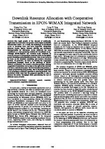
In this paper, we utilize the dynamic FFR that effectively allocates the frequency spectrum to the UEs based on the network loading situations [16]. In this regard, the BW of the FR zone is denoted as BWF , while the BW of PR zones are defined as BWP , BWP , and BWP as shown in Fig. 4. In dynamic FFR, the notion of BBW is utilized, so that extra available BW should be efficiently utilized to that users who need more resources. In this regards, BBW will be assigned dynamically to the users according to their QoS demands. For dynamic FFR, the eNB initially divides the total bandwidth into seven portions as follows:
BTotal BWF BWB BWB BWB Bonus Band
(15)
FR Band
BWP BWP BWP PR Band
Initially, the four portions of the total bandwidth that also contains the BBW are assigned to the FR zone while the rest of the three portions are equally distributed to the PR zones. The following equation shows the equally division of bandwidth in PR zone:
1 BWPR _ BWPR _ BWPR _ (1 FR ) BWTotal 3
(16)
Users belong to the FR and PR zones based on SINR threshold according to (17):
where BTOT is described as whole bandwidth, and BFR and
SINRi SINRThreshold SINRi SINRThreshold
BPR are representing the FR and PR bandwidths, respectively. The normalized FR and PR bandwidths are denoted as FR and
UEi PR Zone UEi FR Zone
(17)
PR , respectively:
FR BFR / BTOT ,
with FR [0,1]
(13)
In the case when number of the users with higher priority are increased in the PR zone then the radius of the FR zone will be reduced, and vice versa. Initially, the BBW is the part of FR zone but when the high priority user are located in the PR zone
Page 7 of 15
2169-3536 (c) 2016 IEEE. Translations and content mining are permitted for academic research only. Personal use is also permitted, but republication/redistribution requires IEEE permission. See http://www.ieee.org/publications_standards/publications/rights/index.html for more information.
This article has been accepted for publication in a future issue of this journal, but has not been fully edited. Content may change prior to final publication. Citation information: DOI 10.1109/ACCESS.2017.2698098, IEEE Access
SINR gain due to CS CoMP b/w LTE-R sectors
SINR gain due to CS CoMP b/w neighbor LTE-R sites
LTE-R eNB
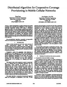
Fig. 8. Rx SINR of LTE-R user with CS CoMP scheme. Interference reduction due to CS CoMP b/w LTE-R sectors
Interference reduction due to CS CoMP b/w neighbor LTE-R sites
Fig. 5. SINR color map for LTE-R eNBs only. Cell edge b/w neighbor LTE-R sectors
Cell edge b/w neighbor LTE-R sites
Fig. 9. Rx interference of LTE-R user with CS CoMP scheme.
LTE-R network coexistence into five diverse scenarios, and evaluate the performance of each scenario. The scenarios’ descriptions and details follow.
Fig. 6. Rx SINR of LTE-R user without CS CoMP scheme.
Cell edge b/w neighbor LTE-R sectors
Cell edge b/w neighbor LTE-R sites
Fig. 7. Rx interference of LTE-R user without CS CoMP scheme.
then it will be assigned to the more demanding PR zone, accordingly. The BBW will be assigned dynamically based on the users’ demands that belongs to the PR zone. So, these spectrum bands are deemed BBW taken out of the FR zone, and would be assigned to the most demanding PR zone. This accomplishes the SINR improvement for cell edge users.
III. LTE-R USER PRIORITY BASED COOPERATIVE COMMUNICATIONS SCHEMES FOR THE COEXISTING PS-LTE AND LTE-R NETWORKS In order to allocate the priority-based resources to the LTER user and analyze the co-channel interference for the coexisting public safety and railway networks, we employ cooperative communications schemes, such as CS-CoMP and dynamic ICIC. In this regard, we categorize the PS-LTE and
A. Scenario 0: only LTE-R eNBs The deployment layout consists of only four LTE-R eNBs following hexagonal sectors, and no PS-LTE eNB is considered in this scenario. Each LTE-R eNB has two sectors with an ISD of 1 km. Fig. 5 shows the color map of the SINR distribution of scenario 0, when only an LTE-R network is deployed. Fig. 6 displays the received (Rx) SINR of the LTE-R user (Train control signal) at the railway track which is located between the LTE-R eNBs. Since railway user moves along the track, so, according to Fig.6, x-axis represents the y-coordinate of the railway user position, while the x-coordinate is supposed to be constant. Moreover, various colors are used to indicate the serving sites of LTE-R UE at different positions. Fig. 6 clearly shows that the signal power is tremendously decreased at the cell edge between neighbor sectors and at the cell edge between neighbor sites because of high interference as well as bad channel conditions, e.g., LTE-R UE received SINR drops below -5 dB at the ranges of 100 m and 50 m from the edges of sectors and sites, respectively. Similarly, Fig. 7 shows the LTE-R UE Rx interference of scenario 0. It can easily be observed that, when LTE-R UE passes through the edges between LTE-R sectors or the edges between LTE-R sites, the LTE-R UE can get high interference and low desired signal power. In order to increase the signal strength at the edges of LTE-R eNB sectors as well as sites, we implement CS CoMP for scenario 0. In this regard, Fig. 8 illustrates that LTE-R user Rx SINR is improved when CS CoMP scheme is employed because it gives the benefit to the cell edge users and also
Page 8 of 15
2169-3536 (c) 2016 IEEE. Translations and content mining are permitted for academic research only. Personal use is also permitted, but republication/redistribution requires IEEE permission. See http://www.ieee.org/publications_standards/publications/rights/index.html for more information.
This article has been accepted for publication in a future issue of this journal, but has not been fully edited. Content may change prior to final publication. Citation information: DOI 10.1109/ACCESS.2017.2698098, IEEE Access
DL Desired Signal DL Interfering Signal
While While PS-LTE PS-LTE UE UE BB receiving receiving higher higher signal signal power power from from LTE-R LTE-R eNB_B eNB_B but but cannot cannot connect connect due due to to no no RAN RAN sharing. sharing.
Railway Network
Public Safety Network
Railway Network Public Safety Network
PS-LTE UE A LTE-R eNB_B PS-LTE UE B
Muting Muting RBs RBs
LTE-R eNB_B
PS-LTE UE_ A
While PS-LTE UE B receives higher signal power from LTE-R eNB_B, it is still connected to PS-LTE eNB_A due to no RAN sharing.
LTE-R UE PS-LTE PS-LTE UE UE BB
PS-LTE eNB_A
LTE-R UE
PS-LTE PS-LTE UE UE needs needs CoMP CoMP assistance. assistance.
PS-LTE eNB_ A
LTE-R eNB_C
LTE-R eNB_C
eNBs eNBs belong belong to to CoMP CoMP site. site.
Fig. 10. LTE-R network coexist with PS-LTE network without RAN sharing.
Fig. 12. Scenario 2: LTE-R network coexist with PS-LTE network without RAN sharing but with CS CoMP.
Start
eNB Selection PS-LTE UEs only access to PS-LTE eNB. LTE-R UE only access to LTE-R eNBs.
Start
eNB Selection PS-LTE UEs only access to PS-LTE eNB. LTE-R UE only access to LTE-R eNBs. LTE-R eNBs only schedule for LTE-R UEs by PF.
PS-LTE eNBs only schedule for PS-LTE UEs by PF.
LTE-R eNBs only schedule for LTE-R UEs by PF.
PS-LTE eNBs only schedule for PS-LTE UEs by PF.
End
Fig. 11. Scenario 1: flow chart of LTE-R network coexist with PS-LTE network without RAN sharing.
reduces the Rx interference. From Fig. 9, it can clearly be seen that by implementing CS CoMP, LTE-R UE can have a high Rx SINR as well as low Rx interference (interference from neighboring LTE-R eNBs/sectors) when it passes through the cell edges. Hence, this performance improvement, i.e., high Rx SINR and low Rx interference, is achieved in scenario 0 by applying CS CoMP among the neighboring LTE-R eNBs. B. Scenario 1: LTE-R Network Coexists with PS-LTE Network without RAN Sharing In this scenario, the network deployment considers LTE-R eNBs to coexist with PS-LTE eNBs without RAN sharing. According to this scenario, public safety and railway networks are overlapped but public safety users cannot connect with railway eNBs because of no RAN sharing between these two LTE networks. This coexisting scenario is exactly same with the coexistence of macro and low power closed subscriber group femto cells. However, railway eNBs are high-power nodes with less coverage mainly targeting the railway track. Hence, public safety users facing sever interference when the railway eNBs are positioned at the cell edge of public safety network. According to Fig. 10. PS-LTE UE_B is located at the cell-edge of public safety network, so, it is receiving very less desired signal power and suffering from strong interfering signal from the railway eNBs because it is also located at the center of railway network. A flow chart in Fig. 11 explains the detailed procedure of this scenario. C. Scenario 2: LTE-R Network Coexists with PS-LTE Network without RAN Sharing but with CS CoMP
If PS-LTE UE needs CoMP assistance ? Yes
No
Give the CoMP assistance to the PS-LTE based on CC2. end
Fig. 13. Scenario 2: Flow chart of LTE-R network coexist with PSLTE network without RAN sharing but with CS CoMP.
In this non-RAN sharing case, we consider CS CoMP between the public safety and railway eNBs. Based on the cooperation among the CoMP sites, the aggressor eNBs mute their PRBs, so, as to not affect the MCS requirements of railway user. However, railway user always has the higher priority while allocating the resources. From Fig. 12, CS CoMP is considered between PS-LTE and LTE-R eNBs, PS-LTE and PS-LTE eNBs, and LTE-R and LTE-R eNBs. In Fig. 13, the flow chart explains the detailed procedure of this scenario. D. Scenario 3: LTE-R RAN Sharing by PS-LTE UEs According to this scenario, railway network enhances the coverage area of the public safety network by providing the access to the public safety users. Hence, railway eNBs providing services to the public safety users instead of giving interference by using the active RAN sharing. Fig. 14 shows the color map of SINR distribution under the RAN sharing environment for coexisting public safety and railway networks. The cell selection for RAN sharing is done z according to (18), where RSRPu is the reference signal receiving power of user u from BS y . Based on RAN sharing scenario, public safety users have the access to attach with
Page 9 of 15
2169-3536 (c) 2016 IEEE. Translations and content mining are permitted for academic research only. Personal use is also permitted, but republication/redistribution requires IEEE permission. See http://www.ieee.org/publications_standards/publications/rights/index.html for more information.
This article has been accepted for publication in a future issue of this journal, but has not been fully edited. Content may change prior to final publication. Citation information: DOI 10.1109/ACCESS.2017.2698098, IEEE Access
LTE-R UE gets high interference from neighbor LTE-R eNB. LTE-R UE gets high interference from center PS-LTE eNB.
Fig. 14. UE SINR distribution for the coexistence of PS-LTE and LTE-R networks with RAN sharing. Start
Start eNB Selection PS-LTE UEs only access to PS-LTE/LTE-R eNBs. LTE-R UE only access to LTE-R eNBs.
eNB Selection PS-LTE UEs access to PS-LTE/LTE-R eNBs. LTE-R UE only access to LTE-R eNBs.
LTE-R eNBs schedule for LTE-R UEs based on CC1.
LTE-R eNBs schedule PSLTE & LTE-R UEs based on CC1.
PS-LTE eNBs only schedule for PS-LTE UEs by PF.
If LTE-R UE needs CoMP assistance ? Yes Give the CoMP assistance to the LTE-R UE based on CC2.
End No
Fig. 15. Scenario 3: Flow chart of railway network sharing by public safety network users.
LTE-R eNB & PS-LTE eNBs schedule for PS-LTE UEs by PF. end
Fig. 17. Scenario 4: Flow chart of railway network sharing by public safety network users with CS CoMP.
PP SS -- LL TT EE U U EE ss cc aa nn aa cc cc ee ss ss tt hh ee LL TT EE -- RR ee N N BB ss w w hh ee nn ii tt rr ee cc ee ii vv ee hh ii gg hh ee rr ss ii gg nn aa ll pp oo w w ee rr ff rr oo m m LL TT EE -- RR (( RR AA N N SS hh aa rr ii nn gg )) ..
Railway Network
PS-LTE eNB_A
Public Safety Network PS-LTE UE A
Muting RBs
LTE-R eNB_B
M M uu tt ii nn gg RR BB ss
PS-LTE eNB_A
PS-LTE UE B
When PS-LTE UE B receive higher signal power from LTER eNB_B, it will connect with it due to RAN sharing.
LTE-R eNB_B
LTE-R UE LL TT EE -- RR U U EE nn ee ee dd ss CC oo M M PP aa ss ss ii ss tt aa nn cc ee ..
PS-LTE UE B
LTE-R eNB_C
LTE-R UE needs CoMP assistance.
LTE-R UE
eNB_C ee N N BB ss bb ee ll oo nn gg tt oo CC oo M M PP ss ii tt ee ..
eNBs belong to CoMP site.
LTE-R eNB_C
Fig. 16. Scenario 4: Railway network sharing by public safety network users with CS CoMP.
railway eNBs. This accomplishes the reduction of co-channel interference and improvement of resource utilization.
Page 10 of 15
Full Reuse (FR): 1 Partial Reuse (PR): 3
Fig. 18. Railway network sharing by public safety network users with ICIC and CS CoMP.
2169-3536 (c) 2016 IEEE. Translations and content mining are permitted for academic research only. Personal use is also permitted, but republication/redistribution requires IEEE permission. See http://www.ieee.org/publications_standards/publications/rights/index.html for more information.
This article has been accepted for publication in a future issue of this journal, but has not been fully edited. Content may change prior to final publication. Citation information: DOI 10.1109/ACCESS.2017.2698098, IEEE Access
start Initialization of Band Bonus BW: initially allocated to FR zone FR band: PR band:
Band Allocation Each cell will occupy only one PR band.
UE Identification Waiting for bonus band
No
No
If the PR zone traffic demand is decreased and no more need of bonus BW ?
If traffic demand of PR zone X is getting high ?
Yes If another PR zone traffic demand is decreased and one bonus band X is released ? (X=B, C or D)
eNB will check the bonus set BWBX for free available bonus BW. Yes
No
Yes
Allocate the bonus band to the PR zone X.
Switch the services which are occupying the requested bonus BW in the FR zone to other available bands. No
end
Fig. 19. Flow chart of railway network sharing by public safety network users with dynamic ICIC.
Moreover, railway user moves along the track and generally experiences strong desired signal power from railway eNBs, so there is no need of PS-LTE RAN sharing by LTE-R UE. Hence, we solely consider the LTE-R RAN sharing by PS-LTE UEs in this paper. Furthermore, PS-LTE and LTE-R eNBs manage their resources based on their own policies, but LTE-R eNBs manage PS-LTE UE based on CC1. A flow chart explains the detailed procedure of scenario 3 in Fig. 15.
Serving_eNB_IDu = argmax (RSRPuy ) y( M N )
(18)
E. Scenario 4: LTE-R Network RAN Sharing by PS-LTE Users with CS CoMP In this scenario, we consider CS CoMP between the eNBs of coexisting public safety and railway networks. Railway eNBs reside nearly half of the coverage of two sectors of center public safety eNB, it means that by uniform distribution of public safety users, approximately half users can be attached with railway eNBs. Though, railway user moves along the track, so it can receive strong enough desired signal power from the railway eNBs but when it passes through the cell edge and also near to the public safety eNBs, it experiences severe interference from neighbor public safety and railway eNBs. To
eliminate this interference, CS CoMP is employed between the PS-LTE and LTE-R eNBs, PS-LTE and PS-LTE eNBs, and LTE-R and LTE-R eNBs, as illustrated in Fig 16. A flow chart explains the detailed procedure of this scenario in Fig. 17. F. Scenario 5: LTE-R Network RAN Sharing by PS-LTE Users with Dynamic ICIC and CS CoMP Note that our scenario of coexisting public safety and railway network is a distinctive heterogeneous network scenario with overlapped macro cells, i.e., public safety and railway eNBs that are deployed by the operators. Based on different cell sizes and railway network offload the public safety network users under the hypothesis of RAN sharing, this deployment is exactly same with heterogeneous network deployment of macro and pico cells, in which users are allowed to attach with both BSs, and pico BSs offload the macro users [15]. However, it is still noticeable differentiation in our scenario because we consider two types of users; public safety users are distributed anywhere and are considered as normal users, but railway user moves along the track placed between the railway eNBs. Pointing this scenario using the RAN sharing, dynamic ICIC can be applied to prevent the interference from the public safety network on the railway network. As for railway user moves along the track located between the railway BSs, it usually
Page 11 of 15
2169-3536 (c) 2016 IEEE. Translations and content mining are permitted for academic research only. Personal use is also permitted, but republication/redistribution requires IEEE permission. See http://www.ieee.org/publications_standards/publications/rights/index.html for more information.
This article has been accepted for publication in a future issue of this journal, but has not been fully edited. Content may change prior to final publication. Citation information: DOI 10.1109/ACCESS.2017.2698098, IEEE Access
TABLE I SYSTEM-LEVEL SIMULATION PARAMETERS Parameters
Values
Carrier Frequency
778 MHz
Bandwidth (Btot)
10 MHz
No. of PS-LTE eNBs
[Only 3 Inner Sectors in the ROI.]
21 Sectors (1-tier, 7 Sites)
No. of LTE-R eNBs
Inter-eNB Distance
Maximum 2 eNBs/Sector beside the Railway PS-LTE eNBs : 4 km LTE-R eNBs : 1 km PS-LTE UEs : 40
No. of UEs/Sector
Fig. 20. UE average throughput; scenario 1~5.
LTE-R UE : 1 (Train Control Signal)
Maximum Antenna Gain
IV. SYSTEM-LEVEL SIMULATION FOR PERFORMANCE EVALUATION OF COOPERATIVE COMMUNICATION SCHEMES
PS-LTE : 3-D Pattern (or 15 dBi)
A. Simulation Environment and Assumptions In this section, we assess the performance of the cooperative communication schemes under various scenarios of coexisting public safety and railway networks. The important simulation parameters are summarized in Table 1. To verify the analysis of co-channel interference under various scenarios, system-level simulations are performed under the one-tier PS-LTE network coexisting with an LTE-R network, as illustrated in Fig 1. The simulations are performed using the channel model considered in Section II. Moreover, instead of full buffer case, practical traffic models are utilized in this paper. We consider two types of traffics, VoIP (80%) and video (20%), for public safety users, while train control signal transmission is assumed to be VoIP traffic. The public safety user are distributed uniformly and randomly throughout the ROI. It is possible that some public safety users will be dropped into the railway BSs region, and it is assumed that there is only one piece of railway user.
LTE-R : 17 dBi Transmission Power Minimum Coupling Loss
PS-LTE : 46 dBm LTE-R : 43 dBm 70 dB
Noise Spectral Density
-174 dBm/Hz
Path Loss Model
Rural Macro (3GPP TR 36.837) Log-normal Distribution (Mean : 0 dB, St. Dev.: 6 dB)
Shadowing
Fast Fading
(Correlation between eNBs/Sectors : 0.5/1) PS-LTE : Winner II (D1-Rural Macro) LTE-R : Winner II (D2a-Rural Moving Networks) PS-LTE UE: 3 Km/h
UE Mobility
LTE-R UE: 250 Km/h
Transmission Modes
SISO (1x1)
Effective SINR
MIESM
UE Receiver
Zero Forcing
Traffic Models Scheduling
PS-LTE : VoIP, Video LTE-R : VoIP Proportional Fair Traffic
receives higher interference power from neighboring raiwaly and public saftey eNBs. To reduce this interference, CS CoMP is employed. Fig. 18 clearly shows the deployment of scenario 5. Moreover, we use the concept of BBW for dynamic resource allocation in order to take care of the users’ QoS priority and demands. Hence, the core purpose to utilize the notion of BBW with FFR scheme is the dynamic assignment of extra bands to the more demanding users. A flow chart explains the detailed procedure of this scenario in Fig. 19.
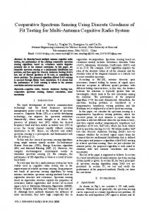
B. Simulation Results and Discussion This section compares the simulation results under various scenarios of coexisting public safety and railway networks in detail. In order to show the benefits attained by the use of RAN sharing between two LTE networks, we compare it with non– RAN sharing scenarios. The performance of the considered scenarios for an LTE-R network coexisting with a PS-LTE network is assessed utilizing the important performance metrics, such as UE average throughput, UE Rx interference, SINR vs. spectral efficiency, and UE outage probability. 1) UE Average Throughput For the aforementioned scenarios, in Fig. 20, we compare the UE average throughput performance at 50% of cumulative distribution function (CDF). In Fig. 20, the comparison clearly indicates that, at 50% of CDF, the RAN-sharing scenario offers better performance than the non-sharing scenario. Moreover, the RAN sharing scenario with CS CoMP is better than all the other scenarios. Scenario 2 gives more throughput than scenario 1 due to the advantages of
Page 12 of 15
2169-3536 (c) 2016 IEEE. Translations and content mining are permitted for academic research only. Personal use is also permitted, but republication/redistribution requires IEEE permission. See http://www.ieee.org/publications_standards/publications/rights/index.html for more information.
This article has been accepted for publication in a future issue of this journal, but has not been fully edited. Content may change prior to final publication. Citation information: DOI 10.1109/ACCESS.2017.2698098, IEEE Access
Fig. 23. UE Rx interference; scenarios 1~5. Fig. 21. SINR vs. spectral efficiency; scenarios 1~4. UE in PR zone
UE in FR zone
5.5 5
Spectral Efficiency [bit/cu]
4.5 4 3.5 3 2.5 2 1.5 1 0.5 -10
-5
0
SINR [dB]
5
10
15
Fig. 22. SINR vs. spectral efficiency; scenario 5.
CS CoMP. In scenario 3, UE throughput performance is 17.11% greater than scenario 1 due to the benefit of RAN sharing, but is approximately similar to scenario 2 (because we consider the CS-CoMP, so, it enhances the overall system throughput). Scenario 4 has better performance than scenario 3 due to the benefits of RAN sharing as well as CS CoMP. In scenario 5, dynamic ICIC has the best edge throughput among all the scenarios, because the users have a better channel condition by using the partial reuse band as well as bonus band allocation. It has the worst peak throughput among all the scenarios due to band partitioning, and the main reason for throughput reduction is that our system is partially loaded. We can clearly observe that CS CoMP in scenario 4, effectively improves the users’ throughput performance, compared to the other scenarios. This throughput enhancement is attained due to two main reasons: (a) RAN sharing provides better channel conditions to the UEs, and more resources are also available for public safety users, and (b) CS CoMP mutes the high interfering eNBs, which reduces the co-channel interference. So, per-user throughput improves, which supports to enhance the overall system throughput. 2) SINR vs. Spectral Efficiency Fig. 21. shows the performance of user SINR versus spectral
efficiency, where the x-axis indicates user SINR, and the y-axis represents the user spectral efficiency in effective data bits per channel use (bits/cu). The spectral efficiency is calculated from adaptive modulation and coding level, and BLER. The selection of modulation and coding level is according to the rule to assure the BLER around 10 %. According to Fig. 21, it can be clearly observed that in scenario 4, the maximum spectral efficiency is higher among all the scenarios, it is just because of the cooperation between the eNBs, in which aggressor eNBs mute their PRBs and users enjoy with good channel condition. Hence, higher modulation and coding levels can be adopted for the users. Moreover, the maximum spectral efficiency in scenario 2 is lower than scenario 4 due to non-RAN sharing, because railway eNBs provide strong interference to the public safety users. Furthermore, in Fig. 21, it is observed that SINR versus spectral efficiency performance curves belongs to corresponding scenarios are almost overlapped, because LTE network uses the same adaptive modulation and coding levels for all the users. Fig. 22 shows the UE SINR versus spectral efficiency performance for dynamic ICIC. UE SINR is averaged over the whole band. Lower SINR is due to the larger path loss for PR users, while there is a higher SINR and a smaller path loss for FR users. UE in a PR zone will be scheduled on the PR band and has a higher SINR and better spectral efficiency due to the partial frequency reuse. A higher modulation and coding level can be used for PR UEs and results in higher spectral efficiency. 3) UE Rx Interference The interference equation is:
Ii
j i , k i
G Nj ,k PjN,k
(19)
where I i is aggregate interference received from all neighboring PS-LTE and LTE-R eNBs without serving eNBs. G Nj,k is the channel gain between the surrounding PS-LTE and LTE-R eNBs for users j and k, respectively, on PRBs N. PjN,k is the transmit power from the surrounding PS-LTE and LTE-R eNBs for users j and k, respectively, on PRBs N. is thermal noise per PRB. In order to express the remarkable interference mitigation
Page 13 of 15
2169-3536 (c) 2016 IEEE. Translations and content mining are permitted for academic research only. Personal use is also permitted, but republication/redistribution requires IEEE permission. See http://www.ieee.org/publications_standards/publications/rights/index.html for more information.
This article has been accepted for publication in a future issue of this journal, but has not been fully edited. Content may change prior to final publication. Citation information: DOI 10.1109/ACCESS.2017.2698098, IEEE Access
V. CONCLUSIONS
Fig. 24. UE outage probability; scenario 1~5.
by using the cooperative communication scheme for coexisting public safety and railway networks, UE Rx interference is compared in a low-level interference region, i.e., with interference below −50 dBm. The results in Fig. 23 clearly illustrated that scenario 2 has less interference than scenarios 1 and 3, because CS CoMP shuts down the high interfering eNBs. For scenario 2, up to 21% of users experienced low interference. In scenario 3, up to 3% of users experienced low interference, while in scenario 1, only 2% of users experienced low interference. Furthermore, in scenario 4, up to 31% of users experienced low interference. Scenario 5 is better than scenario 4 due to the simultaneous benefits of ICIC as well as CS CoMP, i.e., up to 44% of users experienced low interference. Hence, more users receive less interference by using the interference management schemes in scenarios 2, 4, and 5, compared to scenarios 1 and 3. This ensures that, by employing the cooperative communication schemes for coexisting public safety and railway networks, the received level of interference for users lessen tremendously. 4) UE Outage Probability The outage probability equation is:
P(outage) 1 P( SINR SINR _ Threshold )
(20)
where P( SINR SINR _ Threshold ) is the probability when UE Rx SINR is higher than the SINR threshold, and then, UE is not considered to be in outage. It can be clearly seen from Fig. 24 that, the outage probability decreased by using interference management schemes in scenarios 2, 4, and 5, compared to scenarios 1 and 3. Fewer users are in outage in scenario 3 than in scenario 1 due to the benefits of RAN sharing. In scenario 4, the users’ outage probability is less than in scenario 3 due to the advantages of RAN sharing and CS CoMP as well. Scenario 5 is better than all the other scenarios due to the simultaneous benefits of ICIC as well as CS CoMP. Thus, due to the techniques employed above, the link reliability of an LTE-R network is tremendously improved.
This paper provides co-channel interference analysis for the coexisting public safety and railway networks by using cooperative interference coordination schemes. To the best of the authors’ knowledge, this work is the first to take care of LTE-R user priority–based resource allocation and co-channel interference analysis by using cooperative communications schemes for coexisting public safety and railway networks. Moreover, RAN sharing is applied for the coexistence of two LTE networks, which gives greater benefit to users in order to achieve high throughput, as well as a better channel condition. For instance, by using CS CoMP in scenario 4, there is an approximate 60.7% average throughput gain for users, with a significant reduction in UE Rx interference and outage probability. The cause of this improvement is pretty clear; whenever a high-priority user needs CoMP assistance, the other eNBs do not schedule the same resources that have already been allocated to the high-priority UE. It exploits efficient use of spectral resources by implementing cooperation based on users’ QoS priorities. Moreover, the dynamic ICIC in scenario 5 optimizes the throughput of each partial reuse zone according to users’ traffic demands by dynamically assigning the BBW to the higher priority PR zone. Dynamic ICIC provides a significant gain in edge throughput, and lessens UE Rx interference and outage probabilities among all the scenarios by using the PR band as well as bonus band allocation. However, there is degradation in peak throughput by using dynamic ICIC, because the system is partially loaded, and throughput degradation can be compensated for under a fully loaded deployment. This dense deployment would be considered in our future works. ACKNOWLEDGEMENT This work was supported by Institute for Information & communications Technology Promotion (IITP) grant funded by the Korea government (MSIP) (No.2017-0-00316, Development of Fundamental Technologies for the Next Generation Public Safety Communications).
REFERENCES [1]
[2]
[3] [4]
[5]
[6]
J.K. Choi, H. Cho, and K.H. Kim, “Challenges of LTE high-speed railway network to coexist with LTE public safety network,” in Proc. of the International Conference on Advanced Communication Technology, Seoul, Korea, Jul. 2015, pp. 543-547. M. Garcia, I. Alfonso, “Long term evolution in high speed railway environments: Feasibility and challenges,” Bell Labs Technical Journal, vol. 2, no. 18, pp. 237-253, 2014. Further advancements for E-UTRA physical layer aspects, 3GPP TR 36.814 v 9.0, 2010. K. Guan, Z. Zhong, “Assessment of LTE-R using high speed railway channel Model,” in Proc. International Conference on Communication and Mobile Computing, Qingdao, China, Apr. 2011, pp. 461-64. L. Liu, C. Tao, “Position-based modeling for wireless channel on high speed railway (HSR) under a Viaduct at 2.35 GHz,” IEEE Journal on Selected Areas in Communications, vol. 30, no. 4, pp. 834-845, Apr. 2012. W. Chen, I. Ahmad, and K.H.Chang, “Co-channel interference management using eICIC/FeICIC with coordinated scheduling for the coexistence of PS-LTE and LTE-R networks,” EURASIP Journal of Wireless Communication and Network, vol. 2017, no. 34, pp. 1-14, Feb. 2017.
Page 14 of 15
2169-3536 (c) 2016 IEEE. Translations and content mining are permitted for academic research only. Personal use is also permitted, but republication/redistribution requires IEEE permission. See http://www.ieee.org/publications_standards/publications/rights/index.html for more information.
This article has been accepted for publication in a future issue of this journal, but has not been fully edited. Content may change prior to final publication. Citation information: DOI 10.1109/ACCESS.2017.2698098, IEEE Access
[7]
[8]
[9]
[10]
[11]
[12]
[13]
[14] [15] [16]
[17]
[18] [19]
[20] [21] [22]
[23] [24]
[25]
[26]
[27]
[28]
[29] [30]
[31]
D. Xu, R. Ren, "Precoder-and-receiver design scheme for multi-user coordinated multi-point in LTE-A and fifth generation systems,” IET Communications, vol.10, no. 3, pp: 292-299, 2016. I. Ahmad, Z. Kaleem, and K.H. Chang, “QoS priority based femtocell user power control for interference mitigation in 3GPP LTE-A HetNet,” Journal of Korean Institute of Communications and Information Sciences, vol. 39B, no.2, pp. 61-74, Feb. 2014. M. Ali, “An overview on interference management in 3GPP LTE-A heterogeneous networks,” International Journal of Future Generation Communication and Networking, vol. 8, no. 1, pp. 55-68, 2015. Y. Li, Z. Kaleem, and K.H. Chang, “Interference-aware resource sharing scheme for multiple D2D group communications underlying cellular networks,” Wireless Personal Communications, vol. 90, no. 2, pp: 749768, 2016. L. Song, X. Wang, “Joint scheduling and resource allocation for deviceto-device underlay communication,” in Proc. IEEE Wireless Communication and Networking Conference, Shanghai, China, Apr. 2013, pp. 134–139. W. Wei, H. Song, "Imperfect information dynamic stackelberg game based resource allocation using hidden Markov for cloud computing," IEEE Transactions on Services Computing, vol. PP, no.99, pp.1-1, 2016. L. Hentila, M Narandzic, MATLAB implementation of the WINNER phase II channel model ver1.1, 2007. http://www.ist-winner.org/phase_2_model.html. Accessed 10 Jan 2014 Study on radio access network (RAN) sharing enhancements, 3GPP TR 22.852 v 13.1, 2014. Coordinated multi-point operation for LTE physical layer aspects, 3GPP TR 36.819 v 11.10, 2011. Z. Kaleem, B. Hui, and K.H. Chang, “QoS priority-based dynamic frequency band allocation algorithm for load balancing and interference avoidance in 3GPP LTE HetNet,” EURASIP Journal of Wireless Communication and Network, vol. 2014, no. 185, pp. 1-18, Nov. 2014. M. Rahman, H. Yanikomeroglu, “Enhancing cell-edge performance: a downlink dynamic interference avoidance scheme with inter-cell coordination,” IEEE Transactions on Wireless Communication, vol. 9, no. 4, pp: 1414–1425, 2010. Public safety broadband high power user equipment (UE), 3GPP TR 36.837 v 11, 2012. H. Claussen, S. Green, “Efficient modelling of channel maps with correlated shadow fading in mobile radio systems,” in Proc. IEEE International Symposium on Personal, Indoor and Mobile Radio Communications, Berlin, Germany, Sept. 2005, pp. 512-516. Radio Frequency (RF) system scenarios, 3GPP TR 36.942 v12.0, 2014. Physical layer procedures, 3GPP TS 36.213 v 12.5.0, 2015. Z. Hanzaz, H. Schotten, “Analysis of effective SINR mapping models for MIMO OFDM in LTE system,” in Proc. of the International Wireless Communications and Mobile Computing Conference, Italy, Sardinia, July 2013, pp. 1-5. LTE physical layer framework for performance verification, 3GPP R1070674 TSG-RAN Meeting 48, 2007. Evolved Universal Terrestrial Radio Access (E-UTRA) and Evolved Universal Terrestrial Radio Access Network (E-UTRAN) overall descriptions, 3GPP TS 36.300 v 12.5.0, 2015. J. G. Choi, S. Bahk, “Cell-throughput analysis of the proportional fair scheduler in the single cell environment,” IEEE Trans. Veh. Tech., vol. 56, pp. 766–778, 2007. X. Wang, A. Ghosh, Coordinated scheduling and network architecture for LTE macro and small cell deployments, in Proc. of IEEE International Conference on Communication Workshops, Sydney, Australia, June, 2014, pp. 604-609. G. Nardini, A. Virdis, “Effective dynamic coordinated scheduling in LTEAdvanced networks, in Proc. of European Conference on Networks and Communications, Bologna, Italy, Jun. 2014, pp. 1-5. R. Agrawal, N. Arulselvan, “Centralized and decentralized coordinated scheduling with muting, in Proc. of Vehicular Technology Conference, Seoul, Korea, May 2014, pp 1-5. X2 general aspects and principles, 3GPP TS 36.420 v 12.1.0, 2014. J. Wang, L. Chen, “Investigation on CQI definition for CoMP in LTEAdvanced downlink,” in Proc. IEEE 77th Vehicular Technology Conference, Dresdon, Germany, Jun. 2013, pp. 1–5. G. Boudreau, N. Guo, Interference coordination and cancellation for 4G networks," IEEE Communications Magazine, vol. 47, no. 4, pp. 74-81, 2009.
Page 15 of 15
2169-3536 (c) 2016 IEEE. Translations and content mining are permitted for academic research only. Personal use is also permitted, but republication/redistribution requires IEEE permission. See http://www.ieee.org/publications_standards/publications/rights/index.html for more information.