A high-speed integrated optical wireless demonstrator
Dominic C.O’Brien∗a, Grahame E. Faulknera, Kalok Jima, Emmanuel B. Zyamboa, David J. Edwardsa, Mark Whiteheadb, Paul Stavrinoub, Gareth Parryb, Jacques Bellonc, Martin J. Sibleyc, Vinod A. Lalithambikad, Valencia M. Joynerd, Rina J. Samsudind, David M. Holburnd, Robert J. Mearsd, a Department of Engineering Science, Parks Road, Oxford, OX1 3PJ, UK. b Centre for Semiconductor Materials and Devices, Imperial College, Blackett Laboratory, Prince Consort Road, London, SW7 2BZ, UK. c Department of Electronic and Electrical Engineering, University of Huddersfield, Queensgate, Huddersfield, West Yorkshire HD13DH, UK. d Cambridge University Department of Engineering, Trumpington Street, Cambridge, CB2 1PZ, UK. ABSTRACT The widespread use of Optical LANs is dependent on the ability to fabricate low cost transceiver components. These are usually complex, and fabrication involves the integration of optoelectronic and electronic devices, as well as optical components. A number of UK universities are currently involved in a project to demonstrate integrated optical wireless transceiver subsystems that can provide eyesafe line of sight in-building communication at 155Mbit/s and above, using 1550nm eyesafe emitters. The system uses two-dimensional arrays of novel microcavity LED emitters, and arrays of detectors integrated with custom CMOS integrated circuits to implement tracking transceiver components. The project includes design and fabrication of the optoelectronic devices, transimpedance amplifiers and optical systems, as well as flip-chip bonding of the optoelectronic and CMOS integrated circuits to create components scaleable to the large numbers of sources and detectors required. In this paper we report initial results from the first seven channel demonstrator system. Performance of individual components, their limitations and future directions are detailed. Keywords: Optical Wireless, Resonant Cavity LED, Flip-chip bonding, CMOS
1. INTRODUCTION Wireless optical channels have the potential to offer extremely high bandwidth data transmission in a spectrum that is largely unregulated and unlicensed[1]. Line of sight Optical Wireless (OW) systems can offer high bandwidth, as there is no multipath dispersion, and link loss can remain relatively low[2]. This is at the cost of limited coverage however, so that complex transceiver components have to be used to maintain reliable communications over a particular coverage area. Our approach to this is to use tracking transmitter and receiver components, and to use methods to integrate the optoelectronic, optical and other components that are scaleable to the large numbers of devices that would be required for reliable coverage. A number of UK universities are involved in a government funded programme that aims to do this.
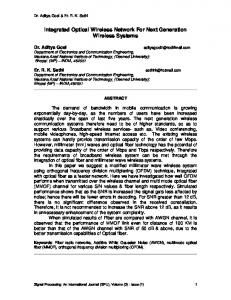
2. SYSTEM OVERVIEW 2.1.Topology Figure 1 shows the system under development. A Base Station (BS) is situated above the coverage area, and this uses a two dimensional array of semiconductor sources that emit normal to their substrate. A lens system is used to map sources in the emitter array to a particular angle, thus creating complete coverage of the space. The use of an array of sources both minimises power transmitted, as sources not pointing at a terminal can be deactivated, and offers the potential for each source to transmit different data. Each terminal within the space has a lens system that collects and focuses the beam of light onto a particular detector within a detector array. The resulting electrical signal is amplified and a data stream is extracted from it. The detector array allows the angle of arrival of the beam to be determined, and hence the direction of the required uplink (from terminal to BS). The system is therefore a combination of a tracking transmitter and tracking receiver. This has the potential to maximise the power available at the receiver (when compared with combinations of tracking and non-tracking components). Each detector has low capacitance and a narrow field of view, thus increasing channel bandwidth and reducing the effect of ambient illumination. ∗
[email protected]; Telephone: + 44 1 865 273916; Fax: + 44 1 865 273906
Base station
Terminal
Figure 1. Optical wireless system
2.2 Integration strategy Figure 2 shows the approach taken to integration. Arrays of sources that emit through their substrate are flip-chip bonded to arrays of driver electronics fabricated in a ‘commodity’ CMOS process. This provides the transmitter functionality, and a similar approach is taken with the receiver photodetector array. . to wired network
Transmitter Base station
~2-3m
Receiver optical system
Receiver
Back illuminated detector flip-chip bonded to driver
Si receiver IC wire bonded to carrier Controller IC Chiprack packaging
PCB
Figure 2. Wireless transceiver integration
In order to test individual components and processes a staged approach to integration has been taken. The initial demonstration in the programme is a 7 channel demonstrator operating at 980nm. Transmitters and receivers are designed to transmit 155Mb/s data that is Manchester line coded before transmission. Single channel CMOS transmitter and receiver integrated circuits are wirebonded to a single channel of the optoelectronic devices, the others being wirebonded to a package that is then connected to external circuitry via a PCB. The final planned demonstrator will use designs from these functionally tested transmitters and receivers and incorporate them in an integrated circuit suitable for flip-chip bonded optoelectronic device arrays. In the following sections the individual components are detailed.
3. OPTOELECTRONIC DEVICES 3.1. Transmitter The system requires two-dimensional arrays of surface emitters that emit through the semiconductor substrate, thus making devices suitable for flip-chip bonding. Resonant Cavity LEDs (RCLEDs) offer sufficient modulation bandwidth for this application and have several characteristics that make them well suited to this application[3]. The beam profile emitted from the device can be tailored by offsetting the cavity resonance of the device from the peak emission wavelength of the material[4]. This detuning causes a beam profile with peak emission away from the optical axis, which improves the illumination profile at the receiver plane. Material was grown by MOVPE, and the wafers then mapped to allow regions with the correct detuning to be identified. These were processed into arrays using standard lithographic techniques. Devices of various sizes were fabricated on a 250µm and 400µm pitch. Figure 3 shows a typical 7 channel RCLED array. Detailed material and device structure and is
400µm pitch array reported in [5]. Figure 3. Resonant cavity LED array
Several processing runs have been attempted in order to validate the approach to processing, using non-optimum parts of wafers from the MOVPE process. The latest run shows high yield and good uniformity of electrical characteristics, but low output power (due to the use of a non-optimum portion of wafer). This is in contrast to early runs that showed high electrical power, but poor uniformity due to the use of too thin passivation and metallisation layer. Together these results make us confident that reliable devices with sufficient power will be possible. Device efficiency was approximately 0.6% for 100mA drive current, with output power of approximately 1mW and a slope resistance of around 3Ω for devices that gave the maximum output optical power. These devices were modulated at up to 310Mb/s, with good modulation performance[5]. The longer term aim of the programme is to use devices operating at wavelengths beyond 1400nm in order to use higher optical powers in the operating environment while still satisfying eye safety regulations[6]. RCLEDs operating at these wavelengths are attractive, in that growth and processing is broadly the same as for the 980nm devices, and designs for these devices are under development.
3.2. PIN structures
500µm pitch array Figure 4. Hexagonal pitch PIN diode array
The detectors for the demonstrations are InGaAs/InP PIN diodes are grown on InP substrates by MOVPE, designed for substrate illumination and operation in the range from 980nm to beyond 1500nm. The device structure is fully reported in [5]. Devices are processed into close packed hexagonal detectors using standard techniques similar to those used for the emitters. Figure 4 shows a typical array. Initially devices suffered from unacceptably high leakage currents, associated with etching the top p-contact to isolate individual detectors in the array. Etching through the I-region and passivating the etched surfaces reduces this problem substantially, but tracks cannot be run over these trenches, so contacts are made to individual devices using wire bonds. This will not be a problem for later flip-chip demonstrators, as contact will be made directly to the rear of these detectors. Devices typically have a measured capacitance of 5.2pF (at 4V reverse bias) compared with a calculated value of 5.1pF for a fully depleted I-region. The slight discrepancy is due to the reduced bias voltage (4V) compared to that required to fully deplete the I region (estimated to be approximately 8V). Leakage current for these devices was in the range 2-140nA. The measured responsivity was 0.39A/W at 980nm, compared with a theoretical maximum of 0.79A/W. Two factors contribute to the reduction in responsivity: the InP substrate has significant absorption at this wavelength, and the Fresnel losses (~30%) as light enters the semiconductor substrate reduce the illumination incident on the PIN structure. An estimate of the likely reduction these two effects produce leads us to believe the detectors are operating efficiently.
4. OPTICAL SYSTEMS Figure 5 shows the transmitter and receiver optical systems. The detailed design of the optical system is described in [5].
Transmitter optical system
~ 2-3m
~5mm ~20mm Receiver optical system Figure 5. Optical system
Transmitter optics
Receiver optics
Figure 6 shows the mounted transmitter and receiver optics. Figure 6. Transmitter and receiver optics
5. SILICON DESIGN The silicon circuitry performs functions local to each source and detector, and global functions that deal with control, arbitration and protocols. Our approach is to use a CMOS (0.7µm Alcatel) process as this allows high levels control functions too be integrated with the ‘front end’ circuitry, albeit with increased difficulty in the design of the analogue stages. Single channel transmitter and receiver circuits have been fabricated for integration into the initial demonstrator. Figure 7 shows the completed integrated circuits.
Transmitter Receiver Figure 7. CMOS transmitter and receiver ICs
5.1. Single channel receiver A single channel pre- and post- amplifier have been designed and fabricated through the Europractice IC foundry service[7]. These have a target sensitivity of –30dBm at a BER of 10-9 and a bandwidth of 217MHz connected to a capacitance of 10pF Testing revealed several problems, and modified circuits are now being fabricated. However, addition of an emitter follower buffer at the output of the preamplifier allows these circuits to be tested. Figure 8 shows the optical-to-electrical frequency response of the amplifier when a 2pF PIN diode is used to source input photocurrent. The measured 3dB bandwidth is approximately 131MHz in this situation. The reduction compared with theory is likely to be due to the additional external components used. Figure 9 shows an eye diagram for 155Mb/s NRZ data taken under these conditions.
Figure 8. Frequency response of amplifier
Figure 9. Eye diagram for test preamplifier
5.2. Single channel drivers Each source has a driver circuit associated with it. These are designed to source 100mA of current at 1.5V, which would yield the required 2.5mW with device efficiencies of around 1.7%. Single channel driver test structures that incorporate novel features have been designed and fabricated [8]. Packaged devices were tested using an electrical model of an RCLED, and a separately packaged RCLED array. The electrical model used a 100pF capacitance in parallel with two diodes to provide the appropriate turn on voltage drop, and then a series connected 1Ω resistor. DC testing with the electrical model showed the devices could source the necessary current to drive RCLEDs, and these could be controlled as predicted. AC tests with this model were also undertaken. The drivers incorporate novel features to improve turn on and turn off, and these were operating as expected. However, bandwidth for both the electrical model and test RCLED array was limited to approximately 7MHz. This was traced to the distributed nature of the large drive transistors, and a modified driver with interdigitated designs has now been submitted. 5.3. Signal combination In order to recover data from the incoming optical power the signal from the desired detector or group of detectors must be routed the data recovery circuit. A three channel combiner that allows arbitrary combination of signals from three preamplifiers has been designed and submitted for fabrication. This is fully reported in an associated proceedings paper[9].
6. SYSTEMS INTEGRATION Initial demonstration Figure 10 shows the layout of the initial transceiver package. The initial demonstration receiver uses a seven channel detector array integrated with a single channel receiver IC, with all connections made by wirebonds. The receiver IC is connected to the central detector of the array, creating one 'fast' channel. The other channels are wirebonded to the package and led to SMA connectors. Decoupling capacitors are attached to the base of the package to allow them to be close to the
9
46 47
(LEAD 1)
(LEAD 6) 10
11
12
(LEAD 14 13)
15
17 16
(LEAD 19 18)
20
21
22
(LEAD 24) 25
26
27
(LEAD 29 28)
30
31
32
35 34
36
37
39
43 42 41 40
44
IC. A partially assembled package, along with the external PCB is shown in Figure 12. The optoelectronic detector IC is designed to be illuminated through the substrate, so a hole is drilled in the base of the package to allow the light to enter it. A thin glass window is attached to the back of the package and the detector array is attached to this, so that the collection optical system can be placed to it. Figure 13 shows this arrangement.
7 6 5
4 3
2
176
7
48 49 50 51
(LEAD 172)
175
8
174 173 172 171 169
53 54
168 167
55 56
166 164
58
(LEAD 169)
(LEAD 165)
(LEAD 160)
163
59
10
60
5
162 161
61
160
62 63 64
159 158
12 156
65
157
(LEAD 153) (LEAD 152)
66
6 31 32
11
3
4
69 8
B
9 11
C
153 152 151
12
150 149 148
E
75
154
9 21
73 74
10
72
B OT
13
29 30
70 71
76
145
147 146
78
3
79 80 81
1
144 143 142 141
4
2 83 84 85
139
86 87 88
136 135 134
132
129
127 128
130 131
(LEAD 129)
(LEAD 123)
125
123 124
122
120
119
118
117 (LEAD 114)
113 (LEAD 110)
114 115
110
109
(LEAD 107)
107 108
105
104
103
102 (LEAD 99)
100
98 99
96 97
93 94 95
91 92
90
126
138 137
Figure 10. Layout of the receiver demonstrator
Figure 12. Partially assembled demonstrator.
(LEAD 141)
6.1. Flip-chip demonstrator Flip-chip bonding allows attachment of the CMOS directly to the optoelectronic ICs, offering low inductance and capacitance, good thermal management and simplification of packaging. Many of the geometrical problems with the initial approach will be solved in the flip-chip bonded demonstrator. A process route that uses bumped CMOS silicon and optoelectronic devices is currently underway.
Adapter Plate
Adapter Plate
Ceramic Package
Ceramic Package
Detector Array
Illumination
Source Array
Transparent substrate
Transparent substrate
Transmitter Optomechanics
Receiver Optomechanics
Figure 13. Optomechanical layout
7. CONCLUSIONS Optical wireless systems offer the promise of extremely high bandwidth subject only to eye safety regulation, and the rising cost of RF spectrum makes this resource increasingly attractive. This paper describes an approach to fabricating optical wireless transceivers that uses devices and components that are suitable for integration, and uses relatively well developed techniques to produce them. The tracking transmitter and receiver components currently being assembled have the potential for use both in the architecture described in this paper, and in diffuse and other network topologies.
ACKNOWLEDGEMENTS The authors would like to thank Geoff Hill, Christine Roberts, John Roberts and Chris Button for growing and processing the optoelectronic devices. This work was funded by the UK Engineering and Physical Sciences Research Council (EPSRC). E.B.Zyambo acknowledges the Rhodes trust for funding.
REFERENCES 1. Street, A.M., et al., "Indoor optical wireless systems - A review". Optical and Quantum Electronics, 29: p. 349-378, 1997. 2. Kahn, J.M., et al., "Imaging diversity receivers for high-speed infrared wireless communication". IEEE Communications Magazine, 36: p. 88-94, 1998. 3. Schubert, E.F., et al., "Temperature and modulation characteristics of resonant-cavity light-emitting diodes". Journal of Lightwave Technology, 14: p. 1721-9, 1996. 4. Stavrinou, P.N., et al., "Angular spectrum of visible resonant cavity light-emitting diodes". Journal of Applied Physics, 86: p. 3475-7, 1999. 5. O'Brien, D.C., et al. "High speed integrated optical wireless transceivers for in-building optical LANs".ed. E.J. Korevaar. Vol. 4124.pp. 104-115. Boston. 2000: SPIE. 6. Lalithambika, V.A., et al. "Development of a CMOS 310Mb/s receiver for free space optical links". Vol. 4214.pp. 124133. Boston. 2000: SPIE. 7. Holburn, D.M., et al. "A CMOS 155Mb/s optical wireless transmitter for indoor networks". Vol. 4124.pp. 124-132. Boston. 2000: SPIE. 8. Holburn, D.M., et al. "Integrated CMOS transceiver for indoor optical wireless links". Vol. 4350.pp. Denver. 2001: SPIE.
1. Street, A.M., et al., "Indoor optical wireless systems - A review". Optical and Quantum Electronics, 29: p. 349378, 1997. 2. Kahn, J.M., et al., "Imaging diversity receivers for high-speed infrared wireless communication". IEEE Communications Magazine, 36: p. 88-94, 1998. 3. Schubert, E.F., et al., "Temperature and modulation characteristics of resonant-cavity light-emitting diodes". Journal of Lightwave Technology, 14: p. 1721-9, 1996. 4. Stavrinou, P.N., et al., "Angular spectrum of visible resonant cavity light-emitting diodes". Journal of Applied Physics, 86: p. 3475-7, 1999. 5. O'Brien, D.C., et al. "High speed integrated optical wireless transceivers for in-building optical LANs".ed. E.J. Korevaar. Vol. 4124.pp. 104-115. Boston. 2000: SPIE. 6. IEC 825-1. Safety of laser products part 1. 1994: British Standards Institution. 7. Lalithambika, V.A., et al. "Development of a CMOS 310Mb/s receiver for free space optical links". Vol. 4214.pp. 124-133. Boston. 2000: SPIE. 8. Holburn, D.M., et al. "A CMOS 155Mb/s optical wireless transmitter for indoor networks". Vol. 4124.pp. 124-132. Boston. 2000: SPIE. 9. Holburn, D.M., et al. "Integrated CMOS transceiver for indoor optical wireless links". Vol. 4350.pp. Denver. 2001: SPIE.