395 Wellington Street. 395, rue Wellington ..... further assumed that the products tfEj, tfGc are luge compared with the d u e s of tcEco and tcGc. On the bais of the ...
A HIGHER ORDER FINITE ELEMENT FOR SANDWICH PLATE ANALYSIS
Saeid G. Oskooei
A t hais subrnit ted in conforrnity wit h the requiremenis for the degree of Master of Applied Science Graduate Department of Aerospace Science and Engineering University of Toronto
@ Copyright by Saeid Oskooei 1998
Library l*lofNational Canada
Bibliothèque nationale du Canada
Acquisitions and Bibliographie Services
Acquisitions et services bibliographiques
395 Wellington Street OüawaON K 1 A W Canada
395, rue Wellington OitawaON KtAON4
Canada
The author has granted a nonexclusive licence allowing the National Library of Canada to reproduce, loan, distribute or sell copies of this thesis in microfonn, paper or electronic formats.
The author retains ownership of the copyright in this thesis. Neither the thesis nor substantial extracts from it may be printed or otherwise reproduced without the author's permission.
L'auteur a accordé une licence non exclusive permettant à la Bibliothèque nationale du Canada de reproduire, prêter, distribuer ou vendre des copies de cette thèse sous la forme de microfiche/nlm, de reproduction sur papier ou sur format électronique. L'auteur conserve la propriété du droit d'auteur qui protège cette thèse. Ni la thèse ni des extraits substantiels de celle-ci ne doivent être imprimés ou autrement reproduits sans son autorisation.
A HIGHER ORDER FINITE ELEMENT FOR SANDWICH PLATE ANALYSIS Saeid G. Oskooei Degree of Master of Applied Science Insti t ute for Aerospace St udies University of Toronto
1998
Abstract A finite element model for the analysis of sandwich plates with laminated composites facesheets is developed. In the model, the face-sheets are represented as Reissner-Mindlin plates and therefore inciude shear deformation efTects. The core is modelled as a threedimensional continuum in which the t hrough-t hickness representation of the displacement fields is of a rnixed form. That is the u.v deflections are cubic functions of
2
while w is
a quadratic function of z. This representation allows accurate modelling of a wide range
of core types (honeycomb and foam) and in particular core materials which have low inplane stiffness cornpared to the transverse stiffness. Also, these through the t hickness trial functions allow an accurate representation of transverse shear and normal stresses. The in-plane modelling of u, v, w use bi-cubic trial functions in both the face-sheets and the core. Such a representation avoids shear locking wit hout speciai precautions. Evaluat ion of the stiffness matrices involves analyticd through-t hickness in tegrat ion of t h e strain energy. Doing so reduces t h e three-dimensional problem to a quasi twndimensionai problem and increases numericd efficiency. Standard finite element procedures are used t o solve the resulting two-dimensional problem.
The presented model provides a powerful general tool for t h e analysis of sandwich plates; transverse normal and shear stresses can be determined explicitly a t the coreffacesheet interface. Also, because of the core model adopted, good accuracy is obtained when large differences in transverse versus in-plane core stiffness is present as well as for cases
in which the core stiffness changes rapidly in the plane of the plate. T h e accuracy of the model is illustrated with several exarnples.
Acknowledgements
1 would like to express my deepest gratitude to my supervisor Professor Jorn S. Hansen for his guidance and advice throughout the course of this thesis. 1 also would like to thank members of my thesis commity, Professor R.M. Measures and Professor J.
Kleiman. 1 would like to take the opportunity to thank Professor James Gottlieb whose great sense of humour makes the group environment more friendly. For his assistance in editing this thesis, 1 want to express my thankfulness to Guillume Renaud.
Finally, this research was made possible by the financial support of Nationd Science and Engineering Research Council of Canada (NSERC) for which 1 am the most grateful.
Contents Abstract
Acknowledgements Contents
List of figures List of tables Nomenclature 1 Introduction
1
..
5
Higher Order Theories . . . . . . . . . . . . . . . . . . . . . . . . . . . . .
6
1.3 The Present Model . . . . . . . . . . . . . . . . . . . . . . . . . . . . . . .
11
1.1 Classical Approach . 1.2
1.4 2
.......................
Outiine of The Thesis . .
. . . . .
........... ........ .. ... ..
. .
Mathematical Model
.......
13 15
........ ... ....... . .. ..... ..
15
2.2 Mathematical Model . . . . . . . . . . . . . . . . . . . . . . . . . . . . . .
15
2.1
Introduction
.......
16
....... .... ...... ..... .. Displacement Formulation . . . . . . . . . . . . . . . . . . . . . . . . . . . Strain and Stress Formulations . . . . . . . . . . . . . . . . . . . . . . . .
16
2.2.1
2.2.2
2.3
2.4
Face-Sheet Modelling .
........ ........
The Core Modelling . .
. .
17 19
3 Finite Element Formulation
3.1 Introduction . . . . . . . . . . . . . . . . . . . . . . . . . . . . . . . . . . .
20
Potentid Energy Cdculation . . . . . . . . . . . . . . . . . . . . . . . . . .
21
3.3 Element Formulation (In-Plane Modelling) . . . . . . . . . . . . . . . . . .
28
Vibration Problem Formdation
32
3.2
4
5
20
4.1
Introduction
...................................
32
4.2
Normal Modes Analysis (Naturd Frequencies) . . . . . . . . . . . . . . . .
33
4.3
Dpamic Problem Formulation
........................
34
4.4
Mass Matrix Formulation
...........................
35
Convergence Study
39
5.1 Introduction . . . . . . . . . . . . . . . . . . . . . . . . . . . . . . . . . . .
39
Rigid Body Motion Test . . . . . . . . . . . . . . . . . . . . . . . . . . . .
39
5.3 Strain Energy Observation . . . . . . . . . . . . . . . . . . . . . . . . . . .
40
5.2
5.4
Uniform in Plane Loading . . . . . . . . . . . . . . . . . . . . . . . . . . .
5.5 Convergence to Classicd Results 5.5.1
41
.......................
41
................
43
Convergence Study Vibration Problem
6 Numerical Examples
44
6.1 Sandwich Plate Loaded By A Concentrated Load . . . . . . . . . . . . . .
14
6.1.1
Frostig Problem . . . . . . . . . . . . . . . . . . . . . . . . . . . . .
44
6.1.2
Thomsen Problem
...........................
50
..................
56
6.3 Sandwich Plate With Stiff Core . . . . . . . . . . . . . . . . . . . . . . . .
61
Vibration Examples . . . . . . . . . . . . . . . . . . . . . . . . . . . . . . .
64
6.4.2
Free Vibration . . . . . . . . . . . . . . . . . . . . . . . . . . . . . .
64
6.4.2
Cornparison With Experimental Resuits . . . . . . . . . . . . . . .
65
6.2
6.4
Sandwich Plate Loaded By Uniform Load
7 Repair/Reinforcing Patch and Its EEect on Natural Frequencies 7.1 Sandwich Plate With Soft Core 7.2
Sandwich Plate With Stiff Core
68
...,.... ......... .. ... . .
68
.......
74
.
,
. ....... .. . ....
8 Conclusion and Summary 8.1
Future Work .
77
.............. ...
. . . .
.....
. . . . .
...
A The composite laminate A . l Mechanical aspect
75 82
................ ..........
. .
...
.
82
B Shear Locking Problem
86
C T h e Finite Elernent Code
89
C.1 Flowchart of The Code . . . . . .
....... ........... ....
.
89
C.2 Data File . . . . . . . . . . . . . . . . . . . . . . . . . . . . . . . . . . .. .
91
List of Figures .
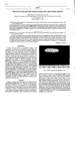
1.1 sandwich panel with (a) foam core (b) honeycomb core. (c) corrugated core
2.1
Schematic of one element . . . . . . . . . . . . . . . . . . . . . . . . . . . .
5.1
Strain energy convergence test . . . . . . . . . . . . . . . . . . . . . . . . .
5.2 Convergence to the classical bearn theory results . . . . . . . . . . . . . . . 5.3 Convergence to the classical plate theory results . . . . . . . . . . . . . . . 6.1
Sandwich plate loaded by a concentrated load . Frostig problem
6.2
Deformation.
W.
. . . . . .
of top and bottom face-sheets. Frostig problem . . . . . .
6.3 Peel stress. oz distribution at core. Frostig problem . . . . . . . . . . . . . Y
6.4
Shear stress. Trz. distribution at core. Frostig problem . . . . . . . . . . . .
6.5 Shear stress. r,,. distribution at core. Frostig problem . . . . . . . . . . . .
.
6.6
In-plane stress. a,. distribution at core Frostig problem
..........
6.7
In-plane stress. a,. distribution at core. Frostig problem
..........
6.8
Bending stress.
0 . .
Frostig problem
distribution at top and bottom of the top facesheet.
................................
6.9 Bending stress. a.. distribution at top and bottom of the top face-sheet. Frostig problem
................................
6.10 Sandwich plate loaded by a concentrated load. Thomsen problem . . . . . 6.11 Deformation.
W. of
top and bottom face-sheets. Thomsen problem . . . . .
6.12 Peel stress. a.. distribution at core. Thomsen problem . . . . . . . . . . . .
6.13 Shear stress.
Tzz7distribution
at core. Thomsen problem
vii
..........
6.14 Shear stress. ry.. distribution at core. Thomsen problem
..........
6.15 In-plane stress. o . distribution at core. Thomsen problem . . . . . . . . . 6.16 In-plane stress. a.. distribution at core. Thomsen problem .
.
.
6.17 Bending stress. a,. distribution at top and bottom of the top face-sheet. Thomsen problern . . . . . . . . . . . . . . . . . . . . . . . . . . . . . . . 6.18 Bending stress. o.. distribution at top and bottom of the top face-sheet. Thomsen problem . . . . . . . . . . . . . . . . . . . . . . . . . . . . . . .
6.19 Sandwich plate loaded with uniform load
..................
6.20 Deformation, w of top and bottom face-sheets. uniform load case . . . . . Y
6.21 Peel stress.
O;
distribution at core' uniform load case . . . . . . . . . . . .
6.22 Shear stress. rr2.distribution at core. uniform load case
.
..........
6.23 Shear stress. rW distri bution at core. uniform load case . . . . . . . . . . . 6.24 In-plane stress. a,.distribution at core. uniform load case . . . . . . . . . 6.25 In-plane stress. o . . distribution at core: uniform load case . . . . . - . . . 6.26 Bending stress. o . distribution at top and bottom of the top face-sheet . uniform load case . . . . . . . . . . . . . . . . . . . . . . . . . . . . . . . 6.27 Bending stress. o.. distribution at top and bottom of the top face-sheet. unifom load case . . . . . . . . . . . . . . . . . . . . . . . . . . . . . . .
6.28 Sandwich plate loaded by concentrated load? honeycomb core
6.29 Deformation.
W.
. . . . . . .
distribution. honeycomb core . . . . . . . . . . . . . . . .
6.30 Peel stress. o.. distribution at core honeycomb core . . . . . . . . . . . . Y
6.31 In-plane stress. or. distribution at the core. honeycomb core . 6.32 Shear stress. ry.. distribution at core. honeycomb core 6.33 First natural mode shape for simply supported piate
.
.
........... ............
6.34 Second natural mode shape for simply suppmted plate . . . . . . . . . . . 6.35 Third natural mode shape for simply supported plate . . . . . . . . . . . . 7.1
Patched sandwich plate. patch number and position
............
7.2 Effect of patch on displacement contours and first natural frequency. foam core
....................................... viii
7.3 Effect of patch on displacement contours and second natural frequency. foam core 7.4
71
Effect of patch on displacement contours and third natural frequency. foam core
7.5
....................................... ......................................
.
72
Effect of patch on displacement contours and forth natural frequency. foarn core
.....................................
A.1 Material and structural sets of coordinates.
73
..................
83
B.l Beam deformation assumptions . . . . . . . . . . . . . . . . . . . . . . . .
Y7
C.l Flowchart of the cornputer code . . . . . . . . . . . . . . . . . . . . . . . .
90
List of Tables 6.1
Cornparison of natural frequencies with MSC/NASTRAN code. free-free
sandwich plate 6.2
.................................
Compaxison of natural frequencies with expenmentd data ported sandwich plate
7.1
.
sirnply sup-
.............................
65
Patch position and percent increase in naturd frequencies of patched smdwichplateswithlowstiffnessfoamcore. . . . . . . . . . . . . . . . . . . .
7.2
65
74
Patch position and percent increase in natural frequencies of patched sandwich plates with high stiffness honeycornb core . . . . . . . . . . . . . . . .
73
7.3 Patch position and percent increase in natural frequencies of patched sandwich plates with different core properties . . . . . . . . . . . . . . . . . . .
76
Nornenclature
Roman Area.
Membrane component of the elast ic mat rix.
Shear component of the elast ic st iffness mat rix. Membrane
/
bending coupling component of the elastic stiffness matrix.
Bending component of the elastic stiffness matrix. Virtud operator. Displacement vector. Young's modulus in ii direction. Force. Force vector. Shear modulus in ij direction.
Strâin energy.
Work done by extemal forces. Stiffness mat rix. Length. Strain
/
displacement matrix.
kth Lagrange polynornial of order i. Number of plies. Basis function.
Displacement interpolation matrix. Reduced elastic stiffness coefficients in material coordinates. Reduced elastic stiffness coefficients in structural coordinates. Thickness.
Bot tom face-sheet t hickness. Top f a c e sheet t hickness Core t hickness.
Half core t hicicness.
+tb to + tt
t0
Displacements in x. y, z directions.
Spatial coordinates.
Greek Nodd displacement vector. Norrnal st rain, Strain vectorShear strain. Poisson's ratio. Plate rotation about x direction.
Plate rotation about y direction. Potent ial Energy.
Densi ty. Normal stress. Stress vector.
Shear stressLocal coordinates in the x!y, z directions.
Interpolating stra.in/dispIacement operator. Total elasticity matrix.
...
Xlll
Chapter 1
Introduction Although the second world war "Mosquiton aircraft is often quoted as the first major structure to incorporate sandwich panels, simdwich structures has been used in many earlier but less spectacular circumstances. Reviewers of the history of sandwich construction compete to nome the first person to describe the principle. But, it seems likely. that the idea of sandwich construction has occurred independently to many engineers at different times; no doubt a curious researcher will eventually find it in the works of the Leonardo
da Vinci. The simplest type of sandwich structure consists of two thin. stiff. strong sheets, referred to as faces or face-sheets, of dense materid separated by a thick layer of low density material which rnay be much less stiff and strong Fig. 1.1. Obviously the bending stiffness of this arrangement is very much greater than that of the single solid plate of the same total weight made of the same materiai as the faces.
A sandwich structural design rnay b e selected in order to satisfy various engineering objectives; for example, to achieve some specific value of density, to give a structure buoyancy, to make the manufacture of ribs simpler, to increase thickness locdly to enable an insert to be fitted flush to the surface, to control a flange thickness to tolerances tighter than axe possible taking into account the variability of reinforcement weightluoit axea,
to receive a geometricd undercut without adding a mass of solid composite. to achieve a specific thermal conductivity, to improve fire resistance, to irnprove acoustic properties,
etc. However, the most common structural reason is to separate the thin stiff face-sheets and thereby increase flexural stiffness and strength wit hout significant ly adding plate mass.
As an illustration, the introduction of a honeycomb core into a solid material so that the
thickness is increased by a factor of four, increases the stiffness thirty-seven times, the strength nine times with only a six percent increase in weight (Potter [l]).Such designs yield very high stiRness to weight as well as strength to weight ratios and are therefore extremely popular in high performance and aerospace vehicles.
Figure 1.1: sandwich panel with (a)foam core, (b) honeycomb core, (c) corrugated core The core must enable the faces to act more or less as the outer layer of a bearn
or plate, and to this end it must possess a certain shear rigidity in planes perpendicular to the faces. It is clear that it is this second property from which the sandwich type of construction derives its outstanding strength and stiffness characteristics.
The core has several vital functions. It must be stiff enough in the direction perpen-
dicular to the face-sheets to ensure that they remain some distance apart. It must be stiff enough in shear to ensure that when the panel is bent the face-sheets do not slide over each other. If this last condition is not fuIfiUed the faces merely behave as two independent beams or panels and the sandwich effect is lost. The core must also be stiff enough to keep the face-sheets nearly flat. Otherwise it is possible for a face to buckle locally (wrinkle) under the influence of compressive stress in its own plane. The core must satisfy al1 these requirements and it is also important that the adhesive should not be so flexible as to permit substantial relative movement of the faces and the core. There are essentidly two different classes of cores, foams and honeycomb, with a great range of materials and properties within each type. Almost any material can be made in the form of foam Fig. 1.1(a),including metals
and glasses, but for practical purposes polymer based foams
lire
the norm. The difference
between polymeric foams is basically from the way they are made and used. The foam mechmical properties is strongly dependence on density as well as constituent materials.
Good bonding between face-sheets and the core is usually fairly easy t o achieve with f o u s because a large surface area is available for bonding. The honeycomb is formed from stripes of thin aluminium ailoy, paper or steel foi1 deformed and joined together Fig.
.l
) . Unlike most foarns, honeycomb is not ao isotropie
material, and the shear properties Vary depending on whether they are tested along the length or across the width. Also' while the through thickness compressive strength is high, the in-plane compressive strength is very low. The corrugated core is a fluted metal sheet attached alternatively to t h e upper and lower faces Fig. l . l ( c ) . Depending on the application of the panel the face-sheets and the core could be made of a wide variety of the materials. Panels for radomes, which must be penneable to radar waves, utilise glass-reinforced plastics for the faces and either the sarne material or resin-impregnated paper for the honeycomb core. Panels for use in t h e building industry have hi therto been of a mainly semi-st nict ural character, cdled upon to carry relat ively small loads over fairly long spans. Building panels, like aircraft panels, should be light in weight but, unlike the aircraft panels, they must be inexpensive. Ali-metal panels may yet find substantial application in buildings but there is also great scope for many other materials.
For face-sheet s, t here are asbestos cement, met ah, fibre reinforced plastics (composite laminates), plywood, hardboard etc. Because composites axe anisotropic it is possible to design a laminate in such a way to match the strengths and loads in various directions.
This is usually regarded as one of the major advantages of composites. New material and combinations of old materials are constantly being proposed and
used.
A wide vaxiety of choices for core and face-sheets is one of the main advantages of the sandwich structures. Depending on the application, the designer can choose the best selection to fdfU the design requirement. The choice of composite Iaminates for the face-sheets gives the designer extra freedom to tailor the properties of the face-sheets and t herefore sandwich structure benefits from t hese unique cbaracteris tics.
In recent years many applications to airplane and missile structures have become known, and sandwich construction appears to have gained a well-established position. Examples of applications are: wing, fuselage and tail plane skins. pressure bulkheads, spar webs, ribs, flooring, radomes. Although the idea of designing a strong, durable md lightweight structure is widely accepted, the design tools are not well established. To solve any problem we always select a mathematical model of a physical problem, and then we try to solve that model. In the
context of structural mechanics the physical problem typically involves an actual structure or structural component subjected to certain assumptions that together lead to differential equations governing the rnathematical model. It should be clear that the solution will only solve this selected mathematical rnodel and that al1 assumptions in this model will be reflected in the solution. We con not expect any more information in the prediction of physicd phenomena than the information contained in the mat hematical model. Hence the choice of an appropriate mathematical model is crucial and completely determines the insight into the actual physicai problem that can obtain by the analysis. A great effort in developing the complete model and design concept of sandwich structures have been done. But because of the complexity of the problem, in al1 those attempts, some assumptions have been made to make the solution possible. These assumptions introduce errors in the
analysis which in some cases leads to misleading results. On the other hand trernendous effort is being made toward the optimisation of sandwich structures, which unveils the
importance of accurate anaiysis. There is no advantage to going through the sophisticated optimisation techniques to improve a structure , when the analysis errors are greater than
the structural gains obtained.
Classical Approach
1.1
The face-sheet/core components of a sandwich construction typically have very different physicd characteristics and as such the analysis of sandwich plates or shells requires a de-
gree of sophistication which is greater than that of classical or Reissner-Mindlin platefsheu theory.
Therefore, sandwich plate problerns have attracted the attention of many re-
searchers. Reissner [2] developed a sandwich plate model, based on honeycomb core characteristics, as a combination of two face-sheets which provide only membrane stiffness separated
by a core which offered only transverse shear stiffness; although the t hrough-thickness stiffness of the core is not explicitly included it is assurned the core inhibits relative t hrought hickness defonnat ion of t be face-sheets.
In the Reissner model in-plane stress in the core and the variation of the face-sheet stress over the thickness of the face-sheet are ignored. The resultant equations permit the analysis of the effect of transverse shear stress deformation and transverse normal stress deformation in the core on the overall behaviour of the plate. It is shown that the effect of the transverse normal stress in the core is very srnaII compared with the effect of the transverse shear stress. Reissner assumed that the thicknesses of the face-sheets are small compared with the thickness of the core and that the values of the elastic constants Ej,Gr for the face-sheets are large compared with the elastic constants of the core, Ec,Gc. He further assumed that the products t f E j , tfGc are l u g e compared with the d u e s of tcEco
and tcGc.On the b a i s of the assurnption that tcEc < t f E f stress of the core ,i.e.
he neglects the in-plane
ECl1= ECz2 = O. Thus, the sandwich plate
was considered as a
combination of two plates without bending stiffness (the face-sheets), and of a t hird plate (the core) offering resistance only to transverse shear stress and transverse normal stress.
In the other words, the core shear deformation dominates the shear deformation of the sandwich plate. The question of primary interest for such a composite plate is whether nonlinear effects have to be taken into account as soon as the transverse deflections are of the order of the face layer thickness. The lirnit of the generd applicability of the Reissner results is the assumptions made concerning order of magnitude of thickness ratio and ratio of elastic constants. This model sets the standud for rnost sandwich plate/shell models. Allen's book [3] on sandwich structures was one of the first comprehensive works on sandwich structures and was an easy guide for designers. As a results of ignoring the in-plane stiffness of the core both Allen and Plantema [4] assumed that shear stress r,
2
in the core is independent of the c w r d i n a t e r and, likewise, the shear strain 7, = is independent of z. This means that the in-plane displacement of the core through its thickness is lineu; that is, plane sections of the core remain plane after deformation. Basically both used the Reissner model. However, Allen in his book acknowledged the limitations of the model m d he specificdy described the comgated core sandwich panel ( s e Fig. l.l(c)) as: "The corrugated core is often stiff enough to make a distinct contribution to the flexural rigidity in the zx-plme but not in the yz-plane. Consequently the usual assumption
that the flexural rigidity of the core is negligible breaks down for bending in the zx-plane
and the shear stress in that plane can no longer be assumed constant over the depth of the core. Fortunately for the simplicity of the analysis, the shear stiffness of the comgated core can u s u d y be taken as infinite in the zx- plane. However, if the analysis is to be done completely for the corrugated-core paoel, it is necessary to introduce additionai terms to represent the strain energy associated with the rx-bending and possibly the twisting of the corrugated-core. To do this would be to destroy the simplicity of the presentation." As it is seen t hey were awaxe of deficiencies in the model but the complexity of the problem was the main obstacle in the way of thorough analysis.
A sandwich beam mode1 which allows anisotropic and composite skins and a core with negligible in-plane stiffness was treated by Holt [ 5 ] , Pemce [6] and Monforton [7]. Sandwich structures in which the normal deflections of the skins are independent variables were considered by Ojalvo [8] although t his malysis ignores the normal stress between the
skin and core.
1.2
Higher Order Theories
The use of even the best foams in aerospace has, in the p u t . been restricted by a feeling that the materials are fragile, especially in terms of vibration and dynarnic loadings. This tended to lead to foam cores being used primarily used as tooling aids, and in the structural andysis it has been commonplace to assume that the foam carries no load at d l . In recent years there has been an increase in the use of foam materials for components where the costs of handling and machining honeycomb are excessive, and these applications have performed well, showing that foam cores can be reliable load bearing materials. Besides, good bonding between face-sheets and the core is usually fairly easy to achieve with foarns
because a large surface axea is available for bonding. It is to be expected then that the use
of foam cores in aerospace wiU continue to increase, as questions of manufacturing costs
become more and more important. Phenomena Like concentration of stress and peeling stress, Le., normal stress between the skins and the core, that do not impose severe restrains on the performance of the traditional sandwich with metailic honeycomb, might, however, be limiting in the case of sandwich plates with soft core. Disregarding these effects rnight be daogerous, leading to an eady sudden failure at a load level much lower than the predicted failure load. The
difference in behaviour between traditional and modern sandwich structures is rnainly due to the transverse flexibility of the core. Modern cores have a very lov rigidity with respect to the face-sheets. These soft cores have characterist ics resembling t hose of t raditiond cores, but due to their very low rigidity, they are also vertically flexible. This flexibility affects the overall behaviour of the sandwich panel in the following ways; 0
It yi.:!ds peeling and shear stress in the core and in the skin-core interface layers
It increases the shear forces and the bending moments in the skins, as well as the stress and deflect ions
It yields unequal deflections in the various skins, relative to panels having the traditiond honey comb core i.e., one in which the longitudinal and the transverse stresses are null, the vertical shear stresses are independent of the vertical coordinate, and
the vertical direction is very stiff.
In al1 models for onalysis of sandwich structures, the basic assumption was that the longitudinal displacement is linear, that is the section plane remains linear after deformation and the vertical displacement is uniform through the depth of the core.
A sandwich structure with a transversely flexible core must be approached with an enhanced theory rat her than the classical theones for the following reasons. The usual basic assumption adopted by keeping the height of the sandwich structure unchanged under al1 circumstances. However, t his assumption is violated when concentrated or partially distributed loads are present. Another assumption is that the section plane of the core remains linear after deformation, which holds as long as the sections of concern are far
from singular conditions, such as supports or the locations of concentrated and partially
distributed loads. In the vicinity of the singulax conditions, the section plane does not remain linear and a concentration of stress, peeling, shear, and intemal resultants in the skins and the core is observed. The requirement that the boundary conditions must be
the same for the entire height of the section is true provided that the core is very stiff verticdy, but it is incorrect whenever soft cores are involved, since the height of the core rnay change. Conditions imposed on one skin do not necessarily hold for the other. For a simply supported plate, it means that the upper skin must be considered as a free edge and the iower skin as simply supported, rather than both being considered sirnply supported. The exact nature of the boundary conditions significiently affects the behaviour in the vicinity of the support and causes a concentration of stress. Eady and sudden failure of these structures is rnainly due to such localised effects. Higher order plate theory as used by Reddy [15] ,[16j allows nonlinear distortions
of the core overcorning the shortcomings encountered in classical t heories. In the higher order theories, it is assumed that the core thickness remains unchanged which implies an incompressible core. Alsot the boundary conditions of both skins are the s m e at the same section and therefore the solution is limi ted to special classes of sandwich panels exhi biting these characteristics. In addition, because of the use of higher order t heory the strain fields through the thickness are continuous and differentiable with respect to z which may lead to physically unrealis t ic result S. Frostig [9], studied the behaviour of sandwich beams wit h foarn cores. He considered the effects of the transverse flexibilit~of the core and peeling stresses between the skin face and the core on the overall bending behaviour. The analysis was carried out by superposition of two types of beam behaviour. The first one, substructure 1: consists of a core with shear rigidity only. The second one, substructure II, allows the core to be flexible in the vertical direction. The main important assumptions used in deriving the governing equations include,
Face-sheet deformat ions following classicd bearn theory 0
The core in-plane rigidity is zero, but can resist shear stresses and transverse normal stresses
The distance between the centroids of the face-sheets are constant As a resuit of the last assurnption
, the shear stresses are uniform throughout 8
the depth
of the core. Besides the vertical displacement of the upper face-sheet, core and the lower face-sheet are identical. This work in spite of these assurnptions, could be considered as the first step toward the comprehensive analysis of sandwich structures with soft core. It enhanced the physicai insight of the beam behaviour, especially under localised loads a d gives some explanations conceming the transverse and shear stresses between the skin and the core. Frostig [IO] takes into account higher-order ( i .e. nonlinear ) effects from the nonlinea.rity of the displacernent field of the core. This high-order analysis considers the skins as ordinary thin beams, acting Iongitudindy ody, and interconnected through equilibrium and compatibility at the interface layers with the core. The core is considered to be a two-dimensional elastic medium. Any type of sandwich beam construction consist ing of metallic or composite laminated (syrnmetric) skins and a transversely flexible core may be considered. Boundary conditions and continuity requirements, which differ from one skin to the other at the same section, are allowed. Loading may be of m y type, but is applied only to the skin. The assumptions used for the entire structure are, O
The skins are considered as ordinary beams with axial and bending resistance.
O
For the core only the shear resistance is considered and the longitudinal stress are assumed to be zero.
0
The shear stress,
T,=
considered to be constant through the thickness and function
of x only, i.e. ( x ,z ) = ( x ) The vertical normal stresses, CL,
in the core is
evaluated only to a Iinear terms. The height of the core and its plane section, then, can take a nonlinear deformed pattern. The additional assumpt ions are that the interface layers are capable of resisting normal and shear stress between the core and the skin, the stress and the deformation fields are uniform through the width, and the loads are applied only at the skins. The andysis models the skin as two beams interconnecting with a core through the cornpatibility and equilibrium, which is considered as a two-dimensional elastic medium. The nonlinear displacement fields through depth of the core were determined. They are cornposed of a parabolic pattern for the verticai deformation, which changes the height of the core, and a cubic pattern for the longitudinal displacement. These nonlinearities are esp e c i d y pronounced in the vicinity of the concentrated or localised distributed loads or
supports. The proposed theory enhances the physical insight of sandwich beam behaviour even under severe singda.r load conditions; it defines the peeling and shear stress a t skincore interface layers, and gives an explanation as to how the shear is transfered from the core to the skins. Frostig [Il] then extends bis previous work on beams to analysis the sandwich panels.
The theory uses classicd plate theory for the skins and a three-dimensional elasticity theory for the core. The assumption used u s u d y follows those encountered in the classical theory of sandwich panels where the core has shear rigidity only and its resistance to inplane longitudinal and transverse normal stress is negligible. In the core, shear stress, rZL and r,,, considered to be constant through the core thickness, i.e. functions of (xly )
only r,,(x, y, r ) = T,,(x, y ) and r,,,(x, y. z ) = r , , ( x , y). The vertical normal stress.
O,?
is
evaluated only to linear terms through the thickness. However no constrains are imposed on the displacement field of the core, which means that the section plane of the core may distort aod its height may change. The high-order effects are results of the theory rather than a priori assumed deflection shapes. The governing equations and the required boundary conditions were derived [I 11 through variational principles, using eight unknowns; the longitudinal, the transverse and the vertical deflections of the upper and the lower skins and the vertical shear stresses on the longitudinal and transverse faces of the core. The boundary conditions in each direction consist of ten geometric and kinematic equilibriurn constraints. For the case of a simply supported sandwich plate this approach Ieads to the set of linear partial differential equations wit h constant coefficients of the order of twenty which is also the required nurnber of boundary conditions. Frostig [12] used t his enhanced model to investigate the localised load effects of sandwich panels with flexible core. The non-linear patterns of the vertical, longitudinal and transverse deformat ions through the depth of the core are high-order effects, which previous theories lack or ignoreThese high-order effects must be considered when transversely flexible cores are concerned.
The work of Frostig [ll],[IO] can be considered as the mnst comprehensive analysis of the sandwich structures. It was a major improvement in theory of sandwich structures. But, the model sufFers from the assurnptions that are necessary to make the solution possible. As mentioned earlier, at the vicinity of the concentrated loads the thickness of the core changes, and deformation of the top and bottom facesheets are not the same. Therefore, assumptions of constant shear stresses and linear peeling stresses should be
lifted ( s e Oskooei [13], and [Ml). Besides, ignoring the in-plane stiffness of the isotropic core ignores the effect of theses terms in strain energy of the sandwich stmcture.
The
classical plate theory used to model the facesheets completely exclude the shear strains and stresses, that is why Frostig açsumed a very thin layer of adhesive at the interface of core and face-sheets to derive the equilibrium formulation. Besides the classical plate
theory does not Qve us any information about possible delamination a s a result of shear stresses in the faces, which is a common problem in laminated plates. Thybo Thomsen (171 used an improved elastic foundation model which extends models incorporating a Winkler foundation model by accounting for the existence of shear interaction between the face-sheets and the core.
This solution
is only applicable to prob-
lems with l o c d y applied concentrated loads, or distributed loads over a very srnall area
[17]. This approxirnate solution will only describe the effects of local bending in the loaded face and the interface between the loaded face and the core material, that is no explicit information is obtained about the decay of the local bending effects through the core material, and no information is available about the stress state of the lower face is affected of the local bending [l?]. Thomsen then includes the interaction between the two face sheets
and transverse shear effects in the face-sheets in his next work [18)
1.3
The Present Mode1
As it is seen, dthough the idea of designing a strong, durable and lightweight structure is widely accepted, because of the cornplexity of the problem some assurnptions must always be made to make a solution possible. Therefore, the design tools suffer from lack of generality and errors introduced in the mode1 because of the assumptions made. That is to Say, many of the existing sandwich models ignore transverse normal and/or shear stresses even though these stresses are crucial in failure analyses. Even the most cornpiete model
[ I l ] has ignored the in-plane stiffness of the core and considered constant shear stresses and linear normal stresses through the core. Besides, the Frostig model [ I l ] , [IO]uses the classicd plate theory to mode1 the face-sheets
, the classical plate theory does not provide
any information about the shear stresses in the face-sheets. It worth mentioning t hat the
shear stress in the face-sheets is the major cause of delamination in the face-sheets. This phenornena cannot be ignored when dealing with laminated plates. The present mode1 takes the core rnodelling ideas of [IO], [II] and combines them with a face-sheet model which includes transverse shear effects, see Oskooei (131, [14].
Furthermore t hese m o d e h g capabilities are used to develop a finite element formulation which should give accurate modeUing with a flexibility to analyse a broad range of sandwich plate problems. In order to include face-sheet shear-deformation effects, the face-sheet model uses Reissner-Mindiin plate theory [21]. Including the shear effects of the face-sheets enhances the model. Shear-locking difficult ies resulting from the finite element representation of the faie-sheets (Shames [21], Bathe [19]) are avoided by adopting bi-cubic Lagrange trial functions (Heppler [20]) for the displacements u, u and W . It may be noted that by explicitly including transverse shear effects in the face-sheets, stress and delarnination analyses of composite face-sheets may be addressed directly and it is expected that more accurate results would be obtained. The core is considered to be a three-dimensional material in which the transverse normal and shear stiffness are much more important (within the context of a sandwich analysis) than the in-plane properties. Therefore, following [1 O] and [Il] in which the core in-plane properties are assurned negligible, it is assumed that u and v are cubic polynomials in r whereas w is quadratic in r . The present model does not assume that the core in-plane properties are negligible; however, this particular representation of u, v , w wiil d o w the effects of negligi ble properties when appropriate. For exarnple, the present model has the capability of reducing to the mode1
G12 to zero. due to Frostig [IO] and [Il] by setting the in-plane core stiffnesses Ell, E2*, Removal of the constraints that are imposed in the previous theories on the deflection pattern through the depth of the core yielded an enhanced theory that allows the description of the real-type structures in which the boundary or continuity conditions at the various skins are different. The nonlinear displacement distribution through the core depth that results from the proposed mode1 allows an accurate implementation of the effects of the core's flexibility on the sandwich plate behaviour. Including the inplane characteristics of the core in the model improves the strain energy formulation. Existance of shear terms in Reissner-Mindlin plate theory ailows the model to balance the shear forces at the interface of the core and face-sheet, therefore there is no need to assume t hat the adhesive layer balances the shear forces at the interface of the core and face-sheet. Besides, Reissner-Mindlin plate theory provides information about shear stress in the face-sheets, which can help more accurate analysis especially for delarnination phenornena. The ability to determine these stresses quantitatively, enhanced the physical explanation for the early
sudden failure that is so cornmon to these type of structures. Disregarding these high-order effects may lead to failure at load levels much Iower than those predicted. The use of this model is highly recomrnended whenever the soit core
are used or localised loads are a concern and where boundary conditions differ £rom one
skin to the other a t the same section. The h i t e element method is used for solution procedure. In the element development, through the thickness integration of strain energy is completed analytically; this leads to computational efficiency and gives the apperuaace of a two-dimensional finite element procedure. In this development, the through-thickness normal (peeling stress) and shear stress are continuous functions of z. Hence, a t any point through the core, stress information is available without through-thickness interpolation; this leads to a more accurate stress analysis with direct implications for failure prediction. The example results presented demonstrate the accuracy of the model. It will be shown that t his finite element capability provides a powerful and flexible tool for the analysis of sandwich plates. Thus, the range of applications for this tool varies from specially designed materid for aerospace applications to thick sandwich slabs used in civil engineering structures. By comparing the results obtained from the ANSYS and NASTRAN h i t e element codes with the results of the presented model, the advantage of the presented model is dernonstrated. The results of the present rnodel are compared with experimental data where available and in ail cases excellent results are obtained.
The mathematical model and its characteristics along with the complete formulations is presented in the next chapter. The presentation and derivation is presented as complete as possible so that reproduction of the present results is possible.
In chapter 3 the finite element formulation and development of the rnatrixes is presented. Due to importance of the dynamic andysis, chapter 4 is devoted to the development of the mat hematical and finite element formulation of the mass matrix. Convergence studies and extensive tests on the formulation derived and the finite element code is completed in chapter 5. Chapter 6 is mainly presents the numerical examples and cornparison of the results from the presented model with other models and experimental results. Chapter 7 is devoted to investigate the effect of the repair/reinforcing patch on the
naturd frequencies and natural modes of vibration. The phenomena which is crucial for the sandwich structures with soft or stiff core and has been totally overlooked. Chapter 8 contains summary, conclusions and the proposed area for the continuation of the work. Appendixes 1 describes the mechanical properties of composite laminates. Appendix
II briefly describes Timoshenko beam t heory (the Reissner-Mindlin plate t heory is extension of the Timoshenko beam theory in two dimension) and the shear locking problem. Appendix III presents the flowchart of the finite element code, the code modeliing capabilities, a brief discussion on the solution procedures especidly for the free vibration case,
and a sample data file is presented at the end.
Chapter 2
Mat hernat ical Model 2.1
Introduction
The importance of a thorough model, which reflects the physical problem properly was mentioned in chapter 1. Again it should be emphasised that the solution will only solve
this mathematical model and that al1 assumptions in this mode1 will be reflected in the solution. We cannot expect any more information in the prediction of physical phenomena than the information contained in the mathematical model. Hence the choice of an appropriate mathematical model is crucial and completely determines the insight into the actual physical problem that can be obtained from the analysis. As seen in Chapter 1, the necessity of a complete and t hrough rnodel for t h e analysis
of the sandwich structures is clear. A robust and thorough model that could be solved easily with the high accuracy sought in aerospace applications. At the same time, t h e model should be able to cover a wide range of applications varying from soft to hard cores
and different kinds of face-sheets. That is, a model is developed that does not suffer from unrealistic assumptions, and after solution provides us with as much as data possible.
2.2
Mathematical Model
The intent of the current formulation is to use an effective three-dimensional finite eiement model but with only a few elements through the thickness. Also, the through-thickness integration will be carried out in closed form which will speed up cdculations and simultaneously give the model a two-dimensional appearance.
For the face-sheets it was feit important to include transverse shear effects in order to
d o w the capture of face-sheet delamination and face-sheet /core dis bounding. Thus the face-sheets are modelled using t hrough-t hickness trial functions which are consistent wit h Reissner-Mindlin plate theory. This theory d o w s modelling of thin to rnoderately thick face sheets. Assumptions of Reissner-Mindlin plate theory are the followings O
Plate could be thin t o moderately thick.
O
Displacements u, v, w are srndl compared to the plate thickness.
O
In-plane strains
O
Transverse normal strain c, is negligible.
O
Transverse shear stresses rZL, iy axeZ parabolic in o.
E,,
%,
E,
are small compare to unity.
Modelling the face sheets using Reissner-Mindlin plate theory. allows the inclusion of shear deformation of face sheets in the overall behaviour of sandwich structure. Appendix
II describes the effect of including the shear terms in the behaviour of a plate in more detail. It should be noted however that the displacement field representation used is not that typically associated with the Reissner-blindlin mode1 (uo,vo, wo: V\ :,
gy),where 3,
and Q, are the rotation like variables. Rather. for each face-sheet, the variables used are (ut,ub,vt,vb, w b )where the subscript t , b refers to the top or bottom of the face-sheet under consideration.
It may be seen that this representation is completely analogous
to the standard representation but it allows a simpler through-thickness assembly using standard finite element ideas. Furtherrnore. the advantage of the standard representation that the membrane and bending problems uncouple (linear analysis, syrnrnetric laminate)
is a nonquestion as the membrane-bending of a face-sheet will never uncouple since the reference surface for the andysis is the sandwich middle-surface.
2.2.2
The Core Modelling
The core trial functions are also chosen to yield special characteristics. In the work by Frostig (101 , [Il] it was noted that for many sandwich core materials the in-plane normal and shear stiffnesses E,,,
Ey9,E, rtre much less t han the t hrough-t hickness counterparts
EzzlE,,, Ezz; thus the assumption was made that Ezz = E, = E,
= O.
This, in turn,
simplifies their analysis considerably but it also dictates a particulor form for the core displacement field. That is, u, v must be cubic functions of z while w is a quadratic fimction of z; there must be this difference in order to allow the neglect of the energy associated with E,,, E,,
E,.
(This is similar to trial function constraints which may be imposed to
avoid shear-locking in Reissner-Mindlin finite element formulations.) It is true that foom core materiais do not exhibit the difference in stiffnesses noted above: however, it is also
E,, E, of foam cores are much less t han the corresponding st iffnesses for the face-sheets and therefore the core strain energy associated with E,,, E,, Ew is small E, t r ~ that e
compared to the corresponding face-sheet strain energy. This again leads to the conclusion that the core stiffnesses E,,,
E,,
E,, rnay be ignored, when appropriate, with the above
implications for the through-thickness form of the t
d functions for u, v , W. Thus in the
current finite element model the core u,u , w are modelled in the form mentioned above. It should be emphasised that in the present formulation the core stiffnesses Ezz:E,,
E,
are not set to zero as in ([lO], [Il], [17]) but are included; however, by adopting the trial function in the form indicated it will allow the strain energy corresponding to these terms to have negligible effect if it is appropriate, that is, a sandwich plate with honey comb core. Also, the use of these trial functions will not induce artificial stiffening.
2.3
Displacement Formulation
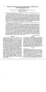
Based on the above, the through-thickness nodal arrangement is determined as illustrated in Fig. 2.1; the nodal degrees of freedom associated with each node are as indicated. Next, the in-plane
(2, y)
trial functions are considered. The use of low-order poly-
nornials for Reissner-Mindlin plate elements leads to shear-locking problems in analysis of thin plates [19], [XI. Appendix II describes the shear-locking problem in more detail. One of the simplest methods to overcome shear-locking is using higher-order approximating polynornials [ZO]; higher-order trial functions also lead to extremely accurate formulations. Therefore bi-cubic triai functions in ( x , y) were adopted to model u, u and w in face-sheets. From compatibility considerations this in turn dictates bi-cubic trial functions in (xly ) for u,v and w in the core. The node layout in the plane is also illustrated in Fig. 2.1. The
trial functions adopted for the displacements take the form summarised below:
Figure 2.1: Schematic of one element
Bottom plate
Core
Top plate
w here;
Strain and Stress Formulations
2.4
Considering only linear terms, the strain-displacement relation for the top or bottom facesheets is
The elasticity matrix, C, for a lamina in the top or bottorn
where
plate is
?&are the lamina stiffness paxameters (Tsai [22]). Appendix II presents more detail
about the lamina stiffness parameters.
For the core, the st rain-displacement relation is
and the elasticity matrix. C, for a lamina in the core is
Chapter 3
Finite Elernent Forrnulation 3.1
Introduction
Analysis of an engineering system requires the ideaiisation of the system into a form that can be solved (the formulation of the mathematical model), the solution of this model. and the interpretation of the results. The main objective of this chapter is to discuss the finite element technique that we choose to solve our mathematicai model. Generally two categories of mathematical models are coasidered: lumped-parameter models and continuum-mechanics-based
models. Also referred to as "discrete-systems"
and "continuous-mechanicsn mat hemat ical models. In a lumped-parameter the formulation of the governing equations led to a set of algebraic equations for the unknown state variables. But for a continuous system the governing equations led to differential equations governing the response. The exact solution of the differential equat ions satisfying al1 boundary conditions is possible only for relatively simple mathematicai models, and
numerical procedures must in generd be employed. These procedures, in essence, reduce the continuous-system mathematicd model to a discrete idealisation that c m be solved in the same manner as a lurnped-parameter model. This is where much of the value of finite element procedures can be found; that is, finite element techniques used in conjunction
wit h digital compu ters have enabled the numerical solution of cont inuous-syst ern mat hematical models in a systematic manner and in effect have made possible the practical extension and application of the classicd procedures to very complex engineering systems. For a continuous system two different approaches can be followed to generate the system of governing equations: the direct method and the variational method, which vari-
ational form is derivable from direct method and for a specific problem both led to the same solution. The variationd method is chosen for solution of the present model. The essence of the approach is to calculate the total potentid
(&O
called d a t i o n a l or functiond) @
of the system and to invoke the stationary value of 8 , that is, 6 9 = O, with respect to the state variables. It can be shown that in elastic problems the total potential energy is not only stationary but is also a minimum [25]. Thus the finite element process seeks such a minimum within the constra.int of an assumed displacernent pattern. The interested reader may refer to
Ref. il91 and [25].
Let @ be the total potentid energy (functional) of the problem. In the traditional Ritz method we substitute the t r i 1 functions
4given by
into 8 and generate n simultaneous equations for the parameters ai using the stationary condition of
which now gives
These trail functions need to sat isfy the essential boundary condit ions. The application of conventional Ri tz process is limited to relatively simple geometrical shapes. The finite element procedure is identical to Ritz procedure, ivith one major difference. In the finite element method these functions need only be piecewise continuous between each adjacent element. Each nodal parameter influencing only adjacent elements, and thus a sparse and usually bonded matrices are formed. The physical domain is approximated as an assemblage of discrete finite elements interconnected at nodal points on the element boundaries. That is why simple trail functions (shape functions) could be used in each of these finite elements for approximation of the unknowns.
The standard formulation for the finite element solution of solids is the displacement rnethod, which is widely used. In this chapter first we establish the governing finite element equations and then discuss the convergence properties of the method.
3.2
Pot ential Energy Calculation
The total potential energy (functional, or briefly potential energy) for linear elastic continuum is
where
Cr is the strain energy of the continuum and W is the total potential of the loads, v
is the volume of the continuum and s is its surface; (81,{P) are the full three-dimensional set of elastic stresses and strains respectively while {ù} are the displacements
,{fB} are
the body forces and {f)are the surface tractions. For a plate v is the plate volume and s is its surface. Because the present development is restricted to lineax geometric and linear elastic considerations, we have
where
[a(Tsai [22]) is the elasticity matrix, which as noted earlier, will be different for
the various plies in the face-sheets as well as in the a x e . Different through-thickness displacement models are adopted for the face-sheets and the core. Thus, in order to develop the finite elernent representation, it is convenient to separate the sandwich plate into three parts, the bottom face-sheet, the core, and the top face-sheet. The aim in this separation is to carry out an analyticol through-thickness
integration with respect to
i
and thereby effectively reduce the mode1 to two dimensions
( x y). In that regard it should be noted that the reference surface for r is the core middlesurface.
Bottom Face-Sheet The strain energy for the bottom face-sheet is
where because the face-sheet is modelled as a Reissner-Mindlin plate, the st ress-st rain relation for each loyer of the composite laminate takes the form
Using the previously presented displacement representation Eq. (2.2), the strain
22
components become z
= ao&+al, z
% = ryz
= bl
+ ko.,
7zz
= ai
+kas
7- = where ( ,,)
bf+hlY 2
+ boJ) + ( a i , + bl,)
(~0.y
( ) , indicate partial differentiation with respect to z- y respectively.
The next step is to integrate the strûin energy analytically with respect to z. Therefore, the strain energy in Eq. (3.5) is first expressed in terms of {z} by substituting for (4) from Eq. (3.6) and then the strains are expressed in terrns of z based on the polynomial expressions in Eq. (3.7). After integration, the strain energy takes the form
where the operator matrix {Cs)is
while the vector of the polynomial coefficients is
{ z d T = [a07 a l ,
60,
hl kol
and
In the above n is the number of plies in the face-sheet and h k , hk-l are the upper and lower z coordinate of each ply, see Appendix 1 or Jones [23]. This result looks very much
like the standard result for laminated composite plates having terms depending on the first, second and third degree of the thickness variable. However, there is one significant difference; that is, the reference plane is at the rniddle-surface of the core. Therefore
hk, hk-i are measured relative to that reference plane. This offset does not influence the A, but does have a significant influence on B, and Dij. With respect to Bi,,the most apparent effect is that even when the face-sheet laminate is symmetric in the conventiond sense Bij does not vanish; symmetry is present only if the entire sandwich is symmetric. In that case the two face-sheets are the mirror image of one another and the Bij's are the negative of one another and câncel only when the finite elements from the face-sheets and core are assembled. The most significant effect of the offset is in the Dii7s which reflects the idea behind a sandwich structure. The next step is to express the polynomial coefficients in the strain energy Eq. (3.8) in t e m s of the through-thickness-nodal
coefficients. With reference to Fig. 2.1 the required
relationship is
where ul,uz,~
2 V, I
,w2 are as illustrated in that figure.
The final step is to introduce the (x,y ) trial functions for ul,U*,w2, u1, tu*; since this step is the s m e for both face-sheets and the core it will be presented for ail three simultaneously later in this section.
Sandwich Core The development for the core follows a similor line to that presented above for the bottom face-sheet
.
The strain energy of the core is
while the stress-strain relation for each layer of the core takes the form
while strain-displacement representation follows from Eq. (2.3) as
Substit uting the various expressions into the strain energy and integrating wit h respect to
z yields the desired result
while
and
and the operator matnx
{cc} is
It is interesting to note that there is coupling of higher order, B, D, EoF, G. H. Also, even ordered coupling terms will vanish for a symmetric core but even then there is still higher order coupling, D, F and H. Also the highest order terms involve the thickness variable t o the seventh power. Again it is necessary to express the polynornial coefficients in the strain energy Eq.
(3.16) in terms of t hrough-thickness-nodal
coefficients. Wi t h reference to Fig. 2.1 the
required relat ionships are
where u2, ...,v2, ...,w2,... are s h o w in Fig. 2.1.
It is to be noted that in the actual implementation, the three relations given above are combined into one expression; the above forrn was used for presentation purposes.
Top Face-Sheet
The formulation for the top face-sheet pardlels that of the bottom face-sheet and will therefore be presented quite briefly. The strain energy is
where the stress-strain relation for each composite iayer takes the form of Eq. (3.6) Using
the previously presented displacement representation Eq. (2.4), the strain cornponents become
€II
= fot
cyy
=
+fi.&
go,y+gl?yt
+
X Z = 91 hovy 71. =
Jl + ho.=
72% =
(f0.Y
+ go.=)+ (f1.Y + ~ 1 s ) ~ 27
Making the appropriate substitutions and integrating with respect to
where the operator matrix
z
yields
{ E t }is
The vector of the polynornial coefficients is
Expressing the polynomial coefficients in terms of through-thickness-nodal
coefficients
yields
where u6,UT,v6, v7, w6 are as illustrated in Fig. 2.1.
3.3
Element Formulation (In-Plane Modelling)
Since the above energy expressions have been integrated with respect to z - the problem has been reduced to a two-dimensional problem in the 15 nodal parameters
u7,V I v2? , v3, v5,u6, VI,w2>w4,736. The representation of the through-thickness-
111, u2, U J , US,u g 3
modelling in terms of these 15 parameters allows a straight-forward 'âssembly' of the contributions from the face-sheets ond the core that is typical of finite element procedures and
therefore every node has the 15 nodal parameters as nodd degrees of freedom; that is, frorn the point of view of the analysis, the 7 through-thickness nodes have effectively collapsed into a single node lying at the core middle-surface. The above matrixes and relations are the starting point for the in-plane two dimensional finite element andysis. In the finite element andysis the physical domain is approximated as an assemblage of discrete elements i n t e r c o ~ e c t e dat nodal points on the element boundaries. The displacements measured in a local coordinate system 2,y, z within each element are assurned to be functions of the displacements at the N finite nodd points. For element rn we have;
where; Nm is the displacement interpolation rnatrix, ü is vector of the global displacement components ui,vi7 and wi at al1 nodal points, and B is the strain-displacement matrix. Considering the first variation of the energy expression, lin = O. with respect to the displacements (which appears in the strain) and using the fact that C is symmetric.
by substituting Eq 3.29 and 3.30 into strain energy expression for each one of bottom face-sheet, core, or top face-sheet and some mathematical manipulation we have
The in-plane (x, y ) tri& functions for the u, v and w nodal coefficients are taken as bi-cubic Lagrange polynornials
based on the excellent performance of such elements Ref. [20]. As seen the finite element formulation considered is displacement-based formulation. By investigating the f o m of the potential energy functional it is observed that the problem is a Co variational problern. Considering the proposed displacement field, it is seen that
the element m e t s the requirements of the monotonie convergence ( Bathe [19]);
0
Element is complete. The dispiacement fimctions of the element are able to represent the rigid body displacements and constant strain states.
0
Element is compatible. The displacement field within the element and across the element boundaries is continuous.
As a result of monotonic convergence the accuracy of the solution will increase continuously as we refine the finite element rnesh. Each bi-cubic element when fully assembled has 112
nodes and 240 degrees of freedom and the corresponding element stiffness matrices and element consistent force vectors are generated iollowing standard finite element procedures. Having established interpolation polynornials and strain displacement matrices, we can now perforrn numerical integration to f o m the stiffness matrices;
Numerical integration uses fourth order Gauss-quadrature which provides exact integration of the strain energy expressions. From an implementatioo point of view. assembly of the global matrices is done in a two step procedure. In the first step the element contributions from the top and bottom face-sheets and the core are calculated separately as sub-element stiffness matrices and are then assembled 'through-the-thickness'
to yield the 'full7element
matrix. Which means
Hence the stiffness matrix for element m is the assemblage of these sub-stiffness
mat rices,
K m = Assemble of KT, Kcm,I(tm
(3.35)
The second step involves the assembly of these full element matrices to form the global st iffness mat rix.
K = Assemble of :=,Km
(3.36)
where n is the number of elements. A similu approach is used for the global force vector.
At this stage the onginal goveming equations is converted to a system of linear equations. Before attempting to solve the system, we have to apply the boundary conditions. Simply for the nodes with h o w n displacement we delete the associated column and row of the K,F and U matrix. After applying the b o u n d q conditions, the system of linear equations simplify to,
KU=F
(3.37)
F is vector of applied loads and U is vector of nodal points displacement, which are unknown. The solution can be done by any standard routine. In present case Gauss elimination procedure was used to solve the system of equations.
Chapter 4
Vibration Problem Formulation 4.1
Introduction
AU structures somehow are subjected to dynamic forces. Nature of dynamic forces are very different, varying fiom simple harmonic forces and seismic forces to very complicated forces occurring during the flight. Therefore design of a structure is not complete unless dynamic analysis as well as static analysis is done. One of the most importaat aspects of dynamic analysis is vibration problem. There are two general classes of vibration problems, free and forced problems. Free vibration takes place when a system oscillates under the action of forces inherent
in the system itself, in absence of external forces. The system under free vibration wiil vibrate at one or more of its natural frequencies, which are properties of the dynarnical system established by its mass and stiffness distribution. Vibration that takes place under the excitation of external forces is called forced
vibration. If the frequency of excitation coincides with the natural frequency of the system a condition of resonance is encountered, and dângerously large oscillations may results. The
failure of major structures, such as bridges, buildings, or airplane wings, is an awesome possibility under resonance. Thus, in the dynomic analysis, calculation of the natural frequencies is of major importance.
4.2
Normal Modes Analysis (Natural Frequencies)
Normal modes analysis cornputes the natural frequencies and mode shapes of a structure. The natural frequencies are the frequencies at which a structure wiIl tend to vibrate if subjected to a disturbance. For example, the strings of a piano are each tuned to vibrate at a specific frequency. The defomed shape at a specific natural frequency is c d e d the
mode shape.
N o m d modes andysis forms the foundation for a thorough understanding of the dynamic characteristics of the structure. Normal modes analysis is performed for many reasons, among them: a
Assessing the dynamic interaction between a component (such as a piece of rotating machinery) and its supporting structure; if the natural frequency of the supporting structure is close to an operating frequency of the component then there can be significant dynarnic amplification of the loads.
a
Assessing the effects of design changes on the dynamic characteristics.
a
Using the modes in a subsequent forced response nnalysis.
O
Using the natural frequencies as a guide to selecting the proper time or frequency step for transient and frequency response analyses, respectively.
O
Assessing the degree of correlation between modal test data and analytical results.
In normal modes andysis we determine the eigenvalues and eigenvectors of the model. For each eigenvalue, which is proportional to a natural frequency, there is a corresponding eigenvector, or mode shape. Each mode shape is similar to a static displaced shape in that there are displacements for each grid point. However, there is one important difference between the mode shape and the static displacements: the scaling. In static analysis the displacements are the true physical displacements due to the applied loads. However, because there is no applied Load in normal mode analysis, the mode shape cornponents c m al1 be scaled by an arbitrary factor for each mode.
If it is necessaq element forces and stresses and reaction forces can be computed in the same manner as for static analysis, with each mode shape treated the same as a set of static displacements.
There are many algonthms to solve the eigenvalue problems. The critena for choosing the proper algorithm is rnainly depends on the size of the matrices in hand and number of eigendues sought. For the present mode1 Subspace method [19] which is one of the best o v e r d methods due to its robustness is chosen.
Dynamic Problem Formulation
4.3
By considering the inertia forces into account, using d'Alembert's principle and treating inertia forces as part of the body forces, the equilibriurn equations in matrix form is
d2 [MIjj$u}
d
+ [CIdi{~}+ [I~]{u}- { F } = O.
where M , ClK, F and u are m a s , darnping, stiffness, extemal forces and displacements respect ively.
In absence of external forces and darnping effects, the equilibrium equations simplify to free vibration form as
[kf]{.Ü} + [K]{u} = O. where
'
(4.2)
means differentiation with respect to time. The solution to the free vibration
problem can be postulated t o be of the form
where q5 is a vector of order R, t is time and X is frequency of vibration of vector #. Substituting Eq. (4.3) into Eq. (4.2) we obtain the so called generalised eigenvalue problem,
from whjch # and X must be determined. The necessary condition to have nonzero solutions for
4 is that the determinaat of the matrix ( I ï - X2M)should be zero.
4.4
Mass Matrix Formulation
The kinetic energy of the sandwich plate is
where p is mass density, zi, ù and w are time differentiation of displacement vector. Because different through-thickness displacement models are adopted for the face-
sheets and the core- Thus, in order to develop the finite element representation, it is convenient to separate the sandwich pIate into three parts, t h e bottom face-sheet, the core, and the top face-sheet. The aim in this separation is to carry out an malytical through-thickness integration with respect to z and t hereby effectively reduce the mode1 to two dimensions ( x ? y). In that regard it should be noted that the reference surface for z is
the core middle-surface.
Bottom Face-Sheet The kinetic energy for the bot tom face-sheet is
With the displacement field considered for our problem, Eq. ( 2.2 ) we have
The next step is to integrate kinetic energy analytically with respect to integration the kinet ic energy takes the f o m
where the vector of the polynornid coefficients is
{&}* = [à*, bol ko, à,, and
b,]
z.
After
In the above n is the number of plies in the face-sheet, (pb)* is mass density of the kth ply of the bottom face sheet and hk, hkdl are the upper and lower z coordinate of each ply (Jones [23]). This result looks very much like the standard result for laminated composite plates having terms depending on the first, second and third degree of the thickness variable. However as mentioned in Chapter 3, there is one significant difference; that is, the reference plane is a t the rniddle-surface of the core. Therefore hh, hk-, are measured relative t o t hat reference plane.
The next step is to express the polynornial coefficients in the kinetic energy Eq. (4.8) in t e m s of t h e through-thickness-nodal coefficients. These relations axe the same as Chapter 3 and is not presented again. The final form of the mass rnatrix for the bottom face sheet is
where Nb is the matrix of shape functions for the bottom face-sheet.
Sandwich Core The developrnent for the core follows a sirnilar line t o that presented above for the bottom face-sheet. T h e kinetic energy of the core is
while ù, v and w of the core are time derivatives of the core displacement field presented before, Eq. (2.3) and therefore is not presented here again. Substituting the various expressioos into t h e kinetic energy and integrating with respect t o z yields to desired resdt
w here
and
Here again coupling of higher order, Bm, Dm, Em, F m , Gm, H m exists. Also, even ordered coupling t e m s will vânish for a symmetric core but even then there is still higher order coupling, Dm, F m and Hm. And the highest order t e m s involve the thickness variable to the seventh power. Polynomid coefficients in the kinetic energy Eq. (4.13) in terms of through-thickness-
nodal coefficients is the same as that presented in Chapter 3 and therefore is not presented
Therefore the core mass matrix is
Top Face-Sheet The formulation for the top face-sheet parallels that of the bottom face-sheet and
will therefore be presented quite briefly. The kinetic energy is
Making appropriate substitutions from displacement field formulations, Eq. ( 2.1 ) and integrating with respect to z yields
while the vector of the polynomial coefficients is
Expressions for the po1pomial coefficients in terms of through-thickness-nodd coefficients
is the sarne as Chapter 3 and is not presented again. Finally, mass matnx for the top face-sheet is
Nt is the top face-sheet shape functions matrix. In-Plane Modelling
In plane modelling has been discussed
Chapter 3 and is exactly the sarne, therefore
is not presented again. Assembly of the mass matrices follow the sarne procedure as the stifhess matrices.
Chapter 5 Convergence Study 5.1
Introduction
Since there is no closed form solution for the problem at haad, to môke sure the formulation of the presented model, the through the thickness integration and the finite element implementation was developed correctly, the code was testeC in every possible way. The testing was carried out from simple checking of the stiffness matrixes to more complex cases in which the behaviour of the sandwich structure should approach the classical plate
results as the core thickness is made vanishingly thin.
5.2
Rigid Body Motion Test
The mode1 should be able to reproduce rigid body motion when no kinematic constrains are imposed on it. It means t hat if we multiply the stiffness matrix of the unconstrained model by a displacement vector which is constant in one direction and zero in other directions the results should be zero. Tests were done a t the element and globd levels. The stiffness matrix at the element and global levels were produced and three matrices of displacement were produced, one with a.U u = 1.0 and u = w = 0.0 the second one with al1 u = w = 0.0 and v = 1.0 and the third one with d u = v = 0.0 and w = 1.0. Multiplication of the stiffness matrix by any of these displacement vectors should yield a zero vector as this product yields the resulting forces acting on the structure. The code passed these tests successfully.
5.3
Strain Energy Observation
As mentioned in Chapter 3 the finite element method used is based on the Ritz method.
Equation (3.2) implies that for equilibrium to be ensured the total potential energy must
be stat ionary for variations of admissible displacements. The finit e element equations derived in the previous sections are simply the statements of this variation with respect to displacements constrained to a finite number of parameters. It can be shown that in elastic situations the total potential energy is not only stationary but is a minimum [24].
Thus the finite element process seeks such a minimum within the constraint of an assumed displacement pattern. The greater the number of degrees of freedom, the more closeiy will the finite element solution approximate to the exact equilib n u m solution, t his assumes the t rue displacement can, in the limit, be approximated by the finite element method. I t is of interest to note
that if the exact equilibrium solution requires an absolute minimum of the total potential energy, an approximate finite element solution obtained usine a displacement approach will always provide an approximate greater than the exact one. Thus a bound on the value of the total potential energy is dways achieved. Hence the strain energy corresponding to the finite element solution is dways smaller than or equd to the strain energy corresponding to the exact solution. Therefore, the error of the finite element solution in the strain energy is minirnised within the possible displacement patterns of a given mesh and that the strain energy corresponding to the finite element solution will approach the exact strain energy (from below) as increasingly finer meshes are used (wit h the displacement pot terns of the finer mesh containing the displacement pattern of the previous coarser mesh). Keeping the above discussion in mind, a uniformly loaded beam was analysed with one, two, four, eight, and sixteen elements respectively. The deformation and the conesponding strain energy in each case is plotted in Fig 5.1. This test showed the appropriate convergence character of the st rain energy and t herefore gives confidence the correctness of the code.
Convergence Study Simply Supported Beam Loaded By Uniform Load T,=4.5 m. T,=0.25 rn, E=130,0e09 bUm2, L-100 m. q=1000 Nlm
One Bernent Two Elements Four Eiements Eight Eiernfmts Sixteen Uements
1.89808 1-91 eû8
C
-0.0007
-
-
-0.0010
"
O
*
'
i
"
25
*
*
~
"
R
'
l
'
50
"
'
-
75
100
Figure 5.1 : Strain energy convergence test
5.4
Uniform in Plane Loading
By applying the uniform load in X, YorZ direction far from the support the strain should be uniform through the thickness in the plane perpendicular to the applied load axes. And if the material properties of the top and bottom face-sheet and the core are the same: then the stress at that section would be the same as well. The code yield the expected results when subjected to a uniform load in X, Y, and Z directions respectively.
5.5
Convergence t o Classical Results
As the thickness of the core decreases the sandwich plate or beam behaviour has to approach the classicai plate or beam theory. A sandwich beam was considered and the deflection of the beam as the core thickness decreased was plotted against the classical beam theory results. The results, Fig 5.2 show excellent convergence to the classical beam theory results. Similar results were obtained for a plate and are presented in Fig 5.3.
Effect Of Core Thickness On Behaviour Of A Sandwich Beam Cornparison With Classicai Beam Theory
Classical Bearn Theory
n
Beam Section
O
25
50
75
100
X(m)
Figure 5.2: Convergence to the classical beam theory resuits Efiect Of Core Thickness On Behaviour Of A Sandwich Plaîe Cornparison With Ciassical Plaie Theory
Plate Thickness
Figure 5.3: Convergence to the classical plate theory results
5.5.1
Convergence Study Vibration Problem
To test the correctness and accuracy of algonthm used for the mass matnx formation the following case was considered. Equation of motion for the system is
In absence of any constraints, if we apply a uniform body force, i.e. gravity force, to the entire structure in one direction, i.e. r , m d consider al1 displacements e q u d to zero except in the direction of the applied load we must have
[ M ] { ü }- { F } = 0.0
(.?.2)
where {ii) is the acceleration vector, and in fact this is the Newton's second law of motion. T h e finite element code passed this test successfully.
Chapter 6 Numerical Examples Based on the new mathematical model presented earlier a finite element code was developed which is able t o analyse any combination of applied loads, boundary conditions and materid properties (Le. soft or high stiffness, isotropic or orthotropic core, and isotropic or orthotropic face-sheets etc.). The code is easy to use and the input data file needs only basic informat ion. T h e mesh generation and node coordinat es are done a u tornatically by the code. First two examples present sandwich plates loaded by a concentrated load. The results are compared with other proposed models by Frostig [ll] and Thomsen [17]. A case of sandwich plate with soft core loaded by uniform ioad is presented next. A sandwich plate with a honeycomb core (Le. stiff core) subjected to a concentrated load is also presented. It is interesting to note that the results of the sandwich plate with honeycomb core confirm the assumptions made by previous sandwich plate models. The results of the presented model for sandwich plates with different core properties unveil the excellent andysis capabili ties of the presented model.
6.1 6.1.1
Sandwich Plate Loaded B y A Concentrated Load Frostig Problem
In order to illustrate the capabilities of the presented model a cornparison to the results of the work presented by Frostig [11] was undertaken as it provides an excellent means of fully evaluating the element capabilities. Ln the example, a sandwich plate is loaded by
concentrated force on the top face-sheet. The geometry and boundary conditions of the sandwich plate are shown in Fig. 6.1; geometric and load symmetry means only a quarter of plate need be analysed.
Plate Description, Frostig Problem
Plate Dimensions: Thicknesses: Core
19.1 mm
Face-S heet s
0.5 mm
Core
E,=52.5 M Pa uc=0.3 & = E2;! = 27.4 G Pa h2= 0.3 GI2 = 1.6 G Pa
Material Properties:
Face-S heets Concentrated Load:
P=50.0 Kg
As the finite element mesh was refined the solution converged very quickly and it was found that a 5x5 mesh provided an excellent discretization of the physicai domain.
Results are presented dong the plate center line, O 5
t
5 150 ; y = 150. Deflections of the
top and bottom face-sheets are presented in Fig. 6.2. Fig. 6.3 illustrates the distribution of the peel stress at different locations through the core. Figures 6.4 and 6.5 present the
shear stress distribut ion in the core. In ai1 previous models because of the ornmission of the in-plane core stiffness, stresses in the X, and Y directions are zero everywhere in the core. Figures 6.6 and 6.7 present the stresses in the X and Y directions in the core. As is seen, especially at the point of load application, these stress components should not be
ignored. The in-plane stress at the top and bottom of the top face-sheet is presented in Fig. 6.8 and 6.9.
__-----,,,,,,------1I1L=---------------
+-=--
Figure 6.1: Sandwich plate loaded by a concentrated load, Frostig problem
Defwmation Distribution Sandwich Plate Lœded By Point Load O.DO05
I
Frostig Pmblem
I
0.OQOOP.
4.m5
-
.o.mm
-
c
6
a n
4.0015
-
4.0020
-
9.0025 0.00
....-.Bottom Plate ( Bottom of The Core )
- Top Plate ( Top 01 The Core )
1
I
0.0s
0.10
0.15
X(m)
Figure 6.2: Deformation, w , of top and bottom face-sheets, Frostig problem
1
Peeling Stress Oistribution Smdwicb Plate Loaded By Point Loed
1
. . . .
5.oE5.
. .
Fmstig Pmblam
.
,
1
- . . .
1
i
0.0m
-5.oES
-
-
-1
-
- To Plate interface d ~ h Core e - - ..- Core - Bottom Plate Interface
-%et
'''Midde
\
-
.am-
-1.SE6
'
'
'
"
'
0.00
'
=
0.05
'
l
'
n
c
*
0.10
X ( m )
0.15
Figure 6.3: Peel stress, u,, distribution at core, Frostig problem
r, Distribution Çendwich Plate Loaded By Point Load i.oe.
I
1
. . . . , Frwtig . . Problem . . , . . . .
1
! 1
1% ;
1
-1 .O=
1
j
,-2.OE5 -
2
z2
-3.OES
-4.OE5
1
L
0.OEO
-
-Core - Top Plate Interface MidQe Of The Core . .. .. Cwe - Bottom Plate Interface
--
'
!
-
-
i
i
i
-
-5.OE5 0.04
(
\
I
'
'
'
"
Figure 6.4: Shear stress,
' 0.05
'
Tzz,
=
'
X ( m )
1
' 0.10
'
'
i
' 0.15
distribution at core, Frostig problem
1
z , Distribution SamMc?'~ Plate Loaded By Point Logd
.
s.ae
4.0B
-
3.0e
-
ZOE5
1
I
10
.
11
. , Fmstig . . Pmblem . . , . . . .
,
l
-
1
!
,
-E
s
4
2
. -.-*-CoreBottom Plate interface
G
l
, ,
e Top Plate Interface
r
- - - Midde OfThe Core
l.OE5
-
I
I
I
I O
1
0
I -t . o e
.
,
,
0.05
,
,
,
x
( rn )
,
,
,
O."
,
1
,
I
0.15
Figure 6.5: Shear stress?ryz,distribution at core. Frostig problern
i
a, Distriburion Sandwich Plate Loadeû By Point L o d
. . " , " Frostig . . Pmblem , . . . .
-Care late interface --uare- Top of TLcote -.
.
. Core - Bottom plate interface
Figure 6.6: In-plane stress, oz,distribution at core, Frostig problem
Distribution Sendiividi ~ l a Loeded k By Point L o d 3
.
0
E
5
~
,
.
Frostig Pmblern .
r
~
.
.
.
v
~
-
-
-
m
1
-Core - Top - . - .-
late interfaat MiMe Of Te ! Coret Core - üonom plate interface
Figure 6.7: In-plane stress, a,, distri but ion at core, Frostig problem
a, Distribution on Lœded Face Sheet
Sandwich Plate Loeded By Point Load Frwtig Problem
-Top 1
.oa
I
!
of the Top Plate
- - -Bottom of the Top Plate
Figure 6.8: Bending stress, a,, distribution at top and bot tom of the top face-sheet , Frostig problem
--
--
a, Distribution on Loaded Face Sheet Sendwich Plate Loaded &y Point Loed
1. O B
f
-Top
-
- -.
of the Top Plate
-Bottom of the Top Plate
Figure 6.9: Bending stress, a,,distribution at top and bottom of the top face-sheet, Frostig problem
Figure 6.10: Sandwich plate ioaded by a concentrated load, Thomsen problem
6.1.2
Thomsen Problem
Thybo Thomsen [17] considered a case which provides an excellent means of fully evaluat-
ing the element capabilities. In the example, a sandwich plate is loaded by concentrated force on the top face-sheet and the results are compared with ANSYS finite element re-
sults. The geometry and boundary conditions of the sandwich plate are shown in Fig.
6.10; geometric and load symmetry means only a quarter of plate need be malysed.
Plate Description, Thomsen problem
Plate Dimensions:
Thicknesses: Core
30.0 mm
Face-S heet s
3.0
Core
E,=O-1 G Pa Ell = 33.6 G P a v12 = 0.32
nim
Material Propert ies:
Facesheet s Concent rated Load:
u,=0.35 EZ2 = 8.4 G Pa
Giz = 3.1 G Pa
P=l000.0 N
A 5x5 mesh provided an excellent discretkation of the physicd domain. Results are presented along the plate center line, O 5 x 5 250 ; y = 250. Deflections of the top and bottom face-sheets are presented in Fig. 6.1 1. Figure 6.12 illustrates the distribution of the peel stress at different locations through the core. Figures 6.13 and 6.14 present the shear stress distribution in the core. In al1 previous models because of t h e omission of the in-plane core stiffness, stresses in the X, and Y directions are zero everywhere in the core. Figures 6.15 and 6.16 present the stress in the
X and Y
directions in the core. -4s is seen,
especidly at the point of load application, these stress components should not be ignored.
The in-plane stress a t the top ruid bottom of the top face-sheet is presented in Figures 6.17 and 6.18.
Deformaiion Distribution
Sendwich Plate Loaded By Point Load
-
.
...... Battom Plate ( Bottom of The C4re )
---
Middle Of The Core -Top Plam Top Of The Coce (
)
Figure 6.11: Deformation, w , of top and bottom face-sheets, Thomsen problem
Peeling Stress Distribution
Sandmch Plate toaded By Point Load
r e - T Plate Interface -C--g Middle O ? T ~Cam Cote - Bottom mate Interface '
''
'
''
Figure 6.12: Peel stress, oz,distribution at core, Thomsen problem
- - - C o r % - Top Plate Interface --Middle Of The Core '
.
--
''
-
Cor8 Battom Plate Interface
Figure 6.13: Sheax stress, rZZ, distribution at core? Thomsen problem
,t Distribution Sandwich Plate Lœded By Point Load
l
-re Top Plate I n t --- Middle Of The Core -.
I
d
- Core Bottom Plate Interface
Figure 6.14: Shear stress,
T,,,
distribution at core, Thomsen problem
a, Distnôution Sandwich Plate Loaded By Point L o d
--- Core - TopAlate interface
~ i d Of e ~ a n .....- Core - üattom plate interface
Figure 6.15: In-plane stress,
O,,
distn but ion at core, Thomsen problem
a, Distribution
,
Sandwich Plate Cmded By Point Load 1
. ... ,
1.2B
l.OB
-
a.oEs
-
6.0E
-
S
.
.
..I.. . - ..
Thornsen Problem
,
,
a
.
m
1
.
1 l
-Midde Core - Top plate interface ..-ûf The Care
!
!
-
...... k e Bottom plate interface
1
1
-2.OE.5 -4.oEs
I
-
-
' " ' " ' " " " ' " ' " " " ' -6.OES 0.00 0.05 0.10 ( ) 0.15
Figure 6.16: In-plane stress,
O,,
0.20
! l
0.25
distribution at core, Thomsen problem
a, Distribution on Loaded FEaat Sht3et Sandmch Plate Laaded By Point L o d
7
i
-Top of the Top Place .-- - -8ottom of the Top Plate
Figure 6.17: Bending stress, a,, distribution at top and bottom of the top face-sheet? Thomsen problem
a , Distribution on Loaded Face Sheet Sandwich Plate Loaâeâ By Point L d
I !
Thomsen Problem
2.0EB
-Top
--
of the Top Plate
- .. .Bottom of the Top Plate
Figure 6.18: Bending stress, a,, distribution at top and bottom of the top facesheet , Thomsen problem
Comparing the results of the present model with Ref. [l?] reveals the capability of the model. The maximum deflection of the top facesheet as predicted by the present model in Fig. 6.11 lies between the maximum presented by elastic foundation model and the ANSYS finite element analysis presented in [l?].In the ANSYS model, Thybo Thomsen[l?] used
1800 isoparametric eight-node solid elements with three translation$ degrees of heedom in each node. As can be seen, even with the very large number of elements used the deflection results are less than those of the presented mode1 and therefore since both analyses are displacement based it may be inferred that the current results are more accurate. It is felt the difference in results is because of poor m o d e h g of the solution (i.e. the elements used in [17] are linear), which in tum yields the stiffer behaviour. It is interesting to note that in spite of the symmetry of loading, geometry, and isotropic core the shear stress, r,and r,,, distribution is not exactly the same. The difference cornes from the orthotropic face-sheets. The same reason describes the difference between cz and a, distribution in top facesheet .
6.2
Sandwich Plate Loaded B y Uniform Load
A sandwich plate loaded by uniform load applied on the top face-sheet with fully clamped boundary conditions is considered. The geometry and boundary conditions are as shown in
Fig. 6.19. Again, because of the symmetry only a quarter of plate is analysed and shown in the figure. The 5x5 element mesh was again used for discretization of the problem. The plate geometry and material properties is the same as in the Thornsen exarnple; the uniform applied load has an intensity P=250.0 N / m 2
Figure 6.19: Sandwich plate loaded with uniform load Results are presented dong the centre line defined by O 5 x 5 250 ; y = 250. In
56
Dekdan Distribution sandmch Plate Loaded By Lkiifoo Load
.- ..- .Bottom Plate ( Bottorn of The Care ) of the Core -Midde Top Plate ( Top Of The Cor8 )
-
-5.OE-6
-
Figure 6.20: Deformation, w, of top and bottom face-sheets, uniform load case Peeling Stress Distribution Sandmch Plate Lœded By Uliform Loed
I
I
l
I I
-&re - Top Plate Interface ---Middle Of The Core --,-..Core Bottom Plate Interface
-
l
Figure 6.21: Peel stress, oz distribution at core, uniform load case
Fig. 6.20 the deformations of the top and bottom face-sheets are presented. Figure 6.21 shows the distribution of peel stress at different locations in the core. The shear stress in the core and bending stress in the core and top face-sheet are presented below. As is seen, even with the soft core the displacement and peel stress distribution in
the core do not Vary through the core thidcness function (i.e. they axe the same for the top,
r, Distribution Sandwich Piate Loadad By Utifami Load
-
4 e Top Plate lnterfaœ - -Middle Of The Core ... - O r e Bottom Plate lnterfam
-
Figure 6 . 2 2 Shear stress,
T,+,
-
distribution at core, uniform load case
r, Distribution Sendmch Piate L d e d By Uniform Load
1
I
4% - Top Plate Intafface
--
-Middle Of The Core . - . .Cam Battom Plate Interface
-
Figure 6.23: Shear stress, r,,, distribution at core, uniform load case
a, Distribution Sandwich Plate Lmded By Uniform Loed
-Core - TopAlate interface ---
Midde of Core ...--Core - Bottom plate interface
Figure 6.24: In-plane stress, oz,distribution at core, uniform load case
--
- -
-
a, Distribution Sandwich Plate Loaded By Uniforni L
d
-Core - Top late interfaœ --Midde Of & Gare Core - Bottom plate interface
....-a
Figure 6.25: In-plane stress, oy,distribution at core, uniform load case
a, Distribution on Loaded Face Sheet
l
1
Sandmch Plate Loaded By Uniforni Loed
-Top of the Top Plate - . - .-Bottom of the Top Plate
Figure 6.26: Bending stress.
O,,
distribution at top and bottom of the top facesheet,
uniform load case
I i
a, Distribution on Loaded Face Sheei Sandwich Plate Lmded By Uniform L o d I
1
OE5
-Top of the Top Plate - .-Bottom of the Top Plaie
S.OE4
Figure 6.27: Bending stress, q,, distribution at top and bottom of the top face-sheet, uniform Ioad case
middle, and bottom of the core). It means that the higher order effects are only crucial for concentrated load cases, or for rapidly varying distributed loads.
6.3
Sandwich Plate With Stiff Core
A sandwich plate with honeycomb core is loaded by concentrated force on the top facesheet. The geometry and boundary conditions of the sandwich plate are shown in Fig. 6.28;geometric and load symmetry means only a quarter of plate oeed be analysed.
Figure 6.28: Sandwich plate loaded by concentrated load, honeycomb core
Plate Description, Stiff Core
Plate Dimensions:
Thi cknesses: Core Face-S heet s Material Propert ies: Core F a c e s heet s Mass Density (Kg/rn3)
Core
F a c e sheet s
1
Defomretion Distribution Sandwich Plate Loaded 0 y Point Coad, H#ieyoomb Core 1.OE-JI..
. . , ... .,. .. .,.. . ., - . . - Bottom Plate ( Bottom of The Core ) : Top Plate ( Top of The Cote ) -
-
-5.063
-
-
" " " ' " " " ' " ' " " " ' -6.063 0.W 0.05 0.10
x
( m ) O.''
0.20
0.25
Figure 6.29: Deformation, w, distribut ion, honeycomb core
r
Peding Stress, , a Distribution sandwich Plate Loaded 8y Point Load Honeycomb Core
Figure 6.30: Peel stress, oz,distribution at core honeycomb core
Stress. a , Distribution Sanâwich Plate Loaded By Foirit Loed. Honeycomb Core 5.wE6
1
.
.
.
.
,
.
.
m
.
I
.
.
.
.
,
.
.
.
.
l
.
.
.
.
4.WB
-
-
3.WE6
-
-
-Top of The Cor6
2.WE6
-. --. .-. -Bottom Midde of The Core of The Core O
*
s.25~2
Si -1.wEs -2.00-
-
-
-
F
-3.ooEb
-4.wEB -5.mEti
0.00
" " " " " " ' " " " " " '
0.05
0.10
x (m)
0.20
0.25
Figure 6.31: In-plane stress, a,, distribution at t h e core, honeycomb core
Peeling Stress. rF Oistribution
1
1
1
Sandmch Plate Loeded 6y Point Load Honeycornb CMe
-Top of The Core
- - - Midde of The Care
...... Rottom of The Core
Figure 6.32: Shear stress, r,, , distri bution a t core, honeycornb core
As can be seen even with a concentrated load, the deformation as s h o w in Fig.
6.29, and the peeling stress as shown in Fig. 6.30, are the same at the top, middle, and bottom of the core. This in t u m means that for a stiff core the previous simple models are capable of predicting the behaviour of the sandwich plate to a good approximation.
At the same time the results shows the excellent modelling capabilities of the presented model. The presented model provides a very strong, robust and general tool for andysis of the sandwich plates with any kind of the core or face-sheet.
Vibration Examples
6.4 6.4.1
Free Vibration
As first test, the of case free vibration of a sandwich plate was considered. The results were compared with the MSCINASTRAN [26] finite element softwâre. The sandwich plate is assumed to have aluminium face-sheets and an aluminium honeycomb core. Material properties of the sandwich plate are
Plate Description
Plate Dimensions:
Thicknesses: Core
F a c e shee t s
6.35 mm 0.4064 mm
Material Properties:
F a c e s heets
ED=65.948 G Pa Gzs=0.1344G Pa E =68.948 G Pa
Core
121.79
Face-S heets
2768.0
Core
Mass Density ( K g / m 3 )
v,=0.33 G23=0.051711 G Pa = 0.32
The results for different discretization of the plate are presented in Table (6.1). The first row of the table presents the number of elements used for discretization of the plate.
NASTRAN uses a 32x32 mesh with 5253 degrees of freedom for the analysis. The u n i f o d y converging results assure the accuracy a d correctness of the algorithm used. Comparing to the NASTRAN results, superiority of the present model becomes clear.
1 de 1 1 1 1 1 / 1 NAST 6x6
4x4
3x3
2x2
1x1
RAN
Table 6.1: Comparison of natural frequencies with MSC/NASTRAN code, Eree-free sandwich plate
EXPER NAST 6 x 6 IMENT RAN
5x5
4x4
3x3
2x2
23.71
23.78
23.84
23-96 25.42
1 -
23.01
23.6
2
43.99
44.86 44.84 45.10 70.32 70.32 1 70.56 70.87 80.01 80.36 50.82 84.91
45
44.49
I
3 4
69
70.01
78
79.08
1
47.10
1x1
51.19
74.32 85.97 93.46
108.15
Table 6.2: Comparison of natural frequencies with experimental data , simply supported sandwich plate
6.4.2
Comparison Wit h Experimental Results
The sandwich plate mentioned above was subject of experimental work by Raville and Ueng [27]. Simple support boundary condition were applied to the plate. The results of the experiment along with the results of NASTRAN ['L6] and the present model are presented in table (6.2). Again, the present model shows excellent results. Displacement contours of the first three natural mode shapes for the plate with simply supported boundary conditions are presented in Figures 6.33 to 6.35.
Figure 6.33: First n a t u r d mode shape for simply supported plate
Figure 6.34: Second natural mode shape for simply supported plate
Figure 6.35: Third natural mode shape for simply supported plate
Chapter 7 Repair/Reinforcing Patch and Its
Effect on Natural Frequencies The need to repair or modify existing structures results from a number of reasons. These typically include repair of darnage such as cracks or corrosion, modifications to overcome a poor design or construction errors and modifications because of change in structural requirements. In addition to the above applications, reinforcing patches are used in sandwich structures that are subjected to concentrated forces or at the connecting joints. Although the use and the design of patches are well developed, some effects of these patches are completely overlooked probably because in most cases they are not important. This chapter is devoted to a very interesting and completely overlooked problem: effect of patches on vibrational behaviour of the sandwich structures. As will be seen, the effect
of patches is considerable for a11 kinds of sandwich plates regardless of core properties i-e. soft or stiff core. The effect is so important that its omission could cause serious problems in practical applications of the sandwich plate.
7.1
Sandwich Plate With Soft Core
A sandwich plate with simply supported boundary conditions and the Listed material properties was considered. The core is an isotropic foam material. A patch was put at different location on the top face-sheet and the efFect of the patch on displacement contours and natural frequencies of the plate was calculated. The thickness and materid properties of the patch are the same as those of the face-sheets.
Figure 7.1: Patched sandwich plate, patch nurnber and position
Low Density Foam Core Sandwich Plate Plate Dimensions: Thicknesses: Core
0.030 rn
Face-S heets
0.00030 mm
Core
E=O.l G Pa
Face-S heets
G:=0.037 G Pa Ell = 154.5 G Pa
Material Properties:
= 0.3 Mass Density
( ~ ~ l r n ~Core ) Face-S heets
121.79 194O. O
Figure 7.1 shows the patch number and the position of the patch for each patch number for the first four natural frequencies. Figures 7.2 to 7.5 present the effect of the patch on displacement contours and naturd frequencies for the first four naturd frequencies. As it is seen the effect is crucial and in some cases it increases the natural frequency more than 50%. Table 7.1 presents naturd frequencies and their change percentage.
Foam core, f1=2.14 Hz Frequency change: 15.88%
1
Frequency change: 23.36%
"
Frequency change: 26.63%
l
Patched, P2. f,=2.64 HZ
Patched, P l , f,=2.48 HZ i
I
I Frequency change: 37.38%
Frequency change: 40.65%
i
Patched, P l 1 , f,=3.35 HZ
Frequency change: 19.62%
Patched, P7, f1=2.94 HZ
Patched, P6. f,=3.01 HZ
Frequency change: 56.54%
Patched, P3, f,=2 .Tl HZ I
'
i i
1j
Patched. P8, f1=2.56 HZ
Frequency change: 42.05%
i
Frequency change: 7.47%
Pl 2, f1=3.04 HZ
/1
Patched,
Patched,
Pl 3, f1=2.30 HZ
Figure 7.2: Effect of patch on displacernent contours and first natural frequency, foarn core
,
1
Displacement contour
Foam core, f2=5.27 HZ p
Freauencv chanae: 4.74%
Frequencv chanrte: 1 1.76%
Frequencv chance: 17.270A
Patched, P l , f2=5.52 HZ
Patched, PZ, f2=5.89 HZ
Patched, P3,f2=6.18 HZ --
Frequency change: 6.07%
Patched, P6, f2=5.59 HZ
'
Frequency change: 8.1 5%
11
Frequency change: 1 0.05%
Frequency change: 7.77%
Patched, P7, fp5.80 HZ
Patched, P8, f2=5.68 HZ
a ; ;: ~~ '
1
1
l
1
1
Patched, P l 1, f2=5.70HZ i
Frequency change: 18.40%
' 1
1
I
Patched, P l 2 , f2=6.24 HZ
i
Frequency change: 26.63%
II 1
j
:: i l
II
't lI jI
Patched, Pl 3, fp5.70 HZ
Figure 7.3: Effect of patch on displacement contours and second natural frequency, foam core
--
-
Displacement contour
Foam core, f3S.86 HZ Frequency change: 9.55%
Frequency change: 7.67%
Patched, P l , fp6.42 HZ
Patched, PZ, fp6.31 HZ
1 I
I
Frequency change: 7.33%
Patched. P3. f3=6.29 HZ
I
Frequency change: 2 4 -2 3%
Frequency change: 11.09%
Patched. P6, f3=7.28 HZ
Patched, P7, f3=6.51 HZ
Freauencv chanqe: 45.22 O h
Freauencv chanae: 14.84%
Frequency change: 57.16%
Patched, Pl 1, f3=8.51 HZ
Patched, P12, f3=6.73 HZ
Patched. P l 3, f3=9.21 HZ
1
Frequency change: 22.69%
Patched. PB. f3=7.19 HZ
Figure 7.4: Effect of patch on displacement contours and third natural frequency, foam core
Displacement contour
Foam core. f4=8.29 HZ I
Frequency change: 8.20%
Frequency change: 12 -30%
Patched, P l . f4=9.31
HZ
,
Frequency change: 17.12%
Patched, P2. f4=8.97 HZ
Patched. P3, f4=9.71 HZ
Frequency change: 2 5.33%
Frequency change: 7.47%
Frequency change: 40.77%
Patched. P6, f4=10.39 HZ
Patched. P7, f4=8.91 HZ
Patched, PB. f4=11.67 HZ
Frequency change: 12.42 %
Freauencv chanae: 12 -06%
, '
t
1
Patched.
Pl 1, f4=9.32 HZ
'
Patched. P l 2, f4=9.29 HZ
1
Frequency change: 13.5 1%
Patched, P l 3, f4=9.41 HZ
Figure 7.5: Effect of patch on displacement contours and forth natural frequency, foarn core
,
Mode Without Patch, f HZ
Pl
P2
P3
P6
Pt3
Pl1
Pl2
Pl3
56.54
42.05
7.47
8.15
18.40 26.63
11.09 22.69 45.22 7.47 40.77 12.42
14.84 57.16
P7
1
2.14
15.88 23.36
2
5.27
4.74
26.63 40.65 (37.38 19.62 11.76 17.27 6.07 10.05 7.77
3
5.86 8.29
9.55
7.67
12-30
8.20
4
1
7.33 24.23 17.12 25.33
13.06
13.51
Table 7.1: Patch position and percent increase in naturai frequencies of patched sandwich plates with low stiffiess foam core
7.2 In this
Sandwich Plate With Stiff Core case a
sandwich plate with a stiff core was considered. Simply supported boundary
conditions are assumed and the material properties are as follows
High Stiffness Honeycomb Core Sandwich Plate
Plate Dimensions:
Thicknesses: Core Face-S heet s
0.030 m 0.00030 m
Material Properties: Core Face-S heet s Mass Density ( K g / m 3 )
Core F a c e s heet s
&=68.948 G Pa GI3=0.1344 G Pa Ell = 154.5 G Pa = 0.3 111.79 1940.0
Again, the patch was put at difTerent location on the top face-sheet and the etfect of the patch on natural frequencies of the plate is calculated. Figure 7.1 shows the patch number and the position of the patch for each patch number.
Mode Without
Pl
P2
P3
P6
P7
P8
Pl1
Pl2
Pl3
55.97
42.42
7.81
7.95
18.95
29.04
Patch, f HZ 1
1.89
2
4.82
3
5.08
4
7.37
16.93 25.58 29.66 41.15 39.55 22.28 8.42 13.80 4.85 9.57 8.42 2.90 12.00 11.68 12.06 26.90 12.39 24.65 13.16 9.02 18.01 25-02 7.68 41-20
48.30 13-53
15.55 61-39 14.36
14.51
Table 7.2: Patch position and percent increase in natural frequencies of patched sandwich plates with high stiffness honeycomb core The results are presented in table 7.2. As is seen, the efFect of the patch on the naturd frequencies of sandwich plates with a soft or stiff cores is very important and should be considered in vibration calculations. This phenomena is a complicated combination of density and stiffness effects. Two
other cases were considered: a sandwich plate with high density foarn core and a sandwich plate with low rigidity honeycomb core. In all cases geometry, boundary conditions, and the face-sheets and patches are the same. Material properties for the high density foarn and the low stiffness honeycomb are as the followings
High Density Foam Core Material Properties:
Core
Mass Density ( K g / m 3 )
Core
Low Stiffness Honeycomb Core Material Properties: Core
Mass Density ( K g / m 3 )
Core
/ 1 Mode
Eiadensity
1
Honeycomb LzDensity
Honeycomb
High rtiffness Low S t i R n r s
Table 7.3: Patch position and percent increase in natural frequencies of patched sandwich plates with different core properties Table 7.3 presents the biggest change of the natural frequency and position of the patch in each case. It is seen that the biggest effect on fint natural frequency happens when the patch is in position 11, see Fig 7.1. The biggest change in second frequency also happens when
the patch is at position 13, Again a patch at position 13 rnakes the biggest difference in dl four cases for the t hird nat ural frequency.
The effect of a patch on natural frequency in sandwich plates is a complicated issue and needs more research. But, as a word of caution, for sandwich plates with soft or stiff core this effect should be considered seriously.
Chapter 8
Conclusion and Summary The fundamental objective of the present work was to develop a higher order model for the analysis of sandwich plates and t o develop a finite element computer code based on this model. The presented model provides an accurate and robust tool for t h e analysis of the sandwich plates. Since Reissner-Mindlin plate theory has been used t o model the facesheets, shear deformation of the face-sheets is explicitly included in t h e analysis; also, the formulation may be used for the analysis of sandwich plates with thin to moderately t hick face-sheets. T h e t hree-dimensiond representation used to model the core response is thought to capture t h e important characteristics of the core and does not include any unnecessary assumptions; therefore, it is felt this dlows a good model of the physicd problem. The elimination of one dimension in the problem by analytical integration through the thickness simplifies the 3-D model by casting it a s 2-D problem which speeds up the problem solution. Finaliy, example calculations illustrate that the solut ion converges very
quickly and gives very good results even with a srna11 number of elements. The preliminary study and results presented for effect of repairlreinforcing patches on n a t u r d frequencies of the sandwich plates is a unique and the first study of this phenomena. The novel mechanicd model, through the thickness integration, and finite element procedure for solution are main characteristics of the presented work which made the presented study a unique, comprehensive, and accurate.
Based on the results presented, it is well justified t o consider t h e present model as one of the best models t o date for the analysis of the sandwich plates.
8.1
Future Work
The presented work bulit as accurate mode1 for the analysis of the sandwich structures. The presented work c o d d be starting point for optimization of the sandwich plates. Effect of ply angles, number of plies, density changes in the core, core thickness, and stiffness changes in the core are a few variables to consider for optimization purposes. The complete study about effect of the patches on natural frequncies of sandwich plates would be another chdenging and interesting continuation of the present work.
References [1] Potter, K., An Introduction to Composite Produets, Chapman & Hall, New York 1997.
[2] Reissner, E., ' Finite Deflection of Sandwich Platesn: Journal of Aerospace Science, Vol. 15, No 7, July 1948, pp. 435-440. [3] Allen, H. G., Analysis und Design of Structural Sandwich Panels, Pergamon Press, London, England, 1969. [4] Plantema, F. J. Sandwich Construction , John Wiley Inc., New York, 1966.
[5] Holt, D. J. md Webber, J. P. H. "Exact Solution to Some Honeycomb Sandwich Beam, Plate and Shell problems." J. Strain Analysis, Vol 17. Mo 1, 1982, pp. 1-8.
[6] Pearce, T. R. A., "The Stability of Simply-Supported Sandwich Panels with Fibre Reinforced Face Platesn, Ph.D thesis, University of Bristol, Bristol: U.K. 1973. [7] Monforton, G. R., and Ibrahim, 1. M. "Modified Stiffness Formulation of ünbdanced Anisotropic Sandwich Platesn, Int. J. Mech. Sci., Vol. 19, pp. 335-343, 1977. [8] Ojdvo, 1. V. uDepartures from Classical Beam Theory in Laminated Sandwich and
Short Beamsn, AIAA J., Vol. 15, No. 10, pp. 1518-1521- 1977.
[9] Frostig, Y. Baruch, M. Vilnay, O.Sheinman, 1. " Bending of Non-Syrnmetric Sandwich Beam with Transversely Flexible Core", J. of Engineering Mechanics, Vol. 117, No.
9, pp. 1931-1952, 1991. (101 Frostig, Y. Baruch, M. Vilnay, O. Sheinman, 1. " High-Order Theory For SandwichBeam Behaviour With Transversely Flexible Coren, J. of Engineering Mechanics, Vol. 118, No. 5, pp. 1026-1043, 1992.
[ I l ] Frostig, Y. Baruch, M., " Higher-Order Bending of Sandwich Panels with -4 Transversely Flexible Coren, AIA A/ASME/ASCE/A HS/ASC Structures, Structural Dynamics, and Material Conference , April 18-20, 1994fHiIton Head, SC.
[12] Frostig, Y. Baruch, M., "Localized Loads Effects in High-Order Bending of Sandwich Panels with Flexible Core", J. of Engineering Mechanics, Vol. 122, No. 11. 1996. [13] Oskooei, S. Hansen, J.S., U A Higher Finite Element For Sandwich Plate Analysis", 39th AIAA/ASME/ASCE/AHS/ASC Structures, Structural Dynarnics, and Material Conference AIA A/ASME/AHS Adaptive Structures Forum, April 20-23, 1998/Long Beach, California. [14] Oskooei, S. Hansen, J.S., "A Higher Finite Element For Sandwich Plate Analysisn: To be published by Inst it ute of Mechanical Engineering, Alborg University, 1998. 1151 Reddy, J. N. Energy and Variational Methods in Applied Mechanics, John Wiley Inc., New York, 1984. [16] Redciy, J. N. " A Review of Refined Theories of Laminated Composite Plates", The Shock and Vibration Digest. Vol. 22, No 7, pp. 3-17, 1990. (171 Thybo Thomsen, O., "Analysis of Local Bending Effects in Sandwich Plates with Ort hotropic Face Layers Subjected to Locdised Loadsn, Composite Structures. Vol.
25, pp. 511-520, 1993. [18] Thybo Thomsen, O., Analysis of Sandwich Panels With Through-the- Thickness Inserts Using a Higher-Order Sandwich Plate Theory, European Space research and Technology Centre, Report EWP-1807, The Netherlands , 1994. [19] Bathe, K-J., Finite Element Procedures, Prentice-Hall Inc., 1996. (201 Heppler, G.R. and Hansen, J.S., "A Mindlin Element for Thick and Deep ShellsRt Computer Methods in Applied Mechanics and Engineering, Vol. 54, pp. 21-27, 1986.
[21] Shames, I.H. and Dym, C., Energy and Finite Element Methods in Structural Mechanics, Hemisphere Publishing Corporation, 1985. [22] Tsai, W. and
Hahn, KT., Introduction to Composite Materials, Technomic Publishing
Company, 1980.
[23] Jones, R.M., Mechanics of Composite Materials, Hemisphere Publishing Corporation, 1975. [24] K . Washizu, Variational rnethods in elasticit y and plasticit y, Pergamon Press, 1968.
(251 Zienkiewicz, O.C., The Finite EZernent Method in Engineering science, McCraw-Hill,
1971. [26] Mario Kataoka Filho., Optirniration of Nonhomogeneous Faceshhets in Composite Sandwich Plates, Ph.D Thesis. UTIAS. Toronto. 1997. [27] Raville, M.E. and Ueng, C.E.S.,Detemination of Naturai Frequencies of Vibratio of
a Sandwich Plate, Experimental Mechanics, pp. 490-493,1967.
Appendix A
The composite laminate A. 1
Mechanical aspect
Six independent material parameters, namely El l , E22u12,G12,G13 and GZ3are needed to characterise ort hotropic materials su b jected to Reissner-Mindlin plate t heory. In addition, the dependent puameter hl is introduced for convenience using the relation1
The subscripts 1,2,3 in these parameters refer to the material coordinates; I being the fibre-direction, 2 being perpendicular to 1 and 3 being normal to the plate. This set of coordinates is illustrated in figure A.1.
The orthotropic constitutive relations expressed in material coordinates is given by
[QI
where the
Qij
are the reduced stiffnesses given as n
Qll
=
fil 1
1- 42v21
'For a more detailed discussion about composite materiais, the interested reader can consult standard textbook such as [22, 231.
Figure A.l: Materid and structural sets of coordinates.
If the plate is rotated through an angle 0: as illustrated in figure -4.1, the material coordinate axes 1,2 do not correspond to the structural axes x. y and the rnaterial is called "rect ilinear anisot ropicn . To relate the stresses and strains in the structural coordinates set, the stiffness matrix
[QIof equation
(A.2) is transformed to
[QI
using relation
where [Tl,the transformation matrix, can be written as
sin28
2 sin 8 cos 9 COS* 0 -2 sin 0 COS 0 sin20 - sin 8 cos 9 sin 0 cos 6 cos28 - sin29 O O O cos 0 -sin 8 sin0 cos 0 O O O COS*
0
1 J
and Reuter's matrix [RI is expressed as
(A. 11)
Using the rotated stiffness matrix [QI, the stress-strain relations expressed in structural coordinates can be written in the form
where the sparse forrn of
[QI
is due to the fact that a11 rotations are relative to the z or 3
axis. The rotated coefficient of thermal expansion are related to the coefficients of thermal
[q [:l 1:
expansion dong the material coordinates by
The strain vector of equation (A.12) is expressed as
fn,
-
7 ;
?Y*
riz
Yzx
%z
+z
nq O O
A laminate composed of several plies at different angles can be characterised using equation (A.12) since it depends on on arbitrary angular shift between structural and material coordinates. To consider a multi-layered Iaminate as a single Iayer, an integration over its thickness must be performed in order to find the equivalent properties. Total in-plane forces, moments and shear forces are obtain by integrating the stress vector over the thickness of t h e laminate. Those quantities, expressed per unit of length, are
(A. 14)
where hk correspond to the distance between the top of the kth ply and the mid-surface of the laminate., htegrating the right hand side of the constitutive relation (A.12) with the strains explicitly defined in terms of the z coordinate of equation (A.13), the total forces and moments take the form
where the coefficients A i j , Bi,, DG and
Ai, are defined as
Appendix B Shear Locking Problem This appendix is devoted to describe the Reissner-Mindlin plate theory and shear locking problem. For a better presentation and less complicated figures it is easier to describe the Tirnoshenko beam theory first. The Reissner-mindlin plate theory is simply the extension of the Timoshenko beam theory in two dimension. Let us first discuss some basic assumptions pertaining to the formulation of beam elements. The basic assumption in beam bending andysis excluding shear deformations is that a normal to the midsurface (neutral axis) of the beam remains straight during deformation and that its angular rotation is equd to the dope of the beam midsurface. This kinematic ossumption, illustrated in Fig. B.l(a), corresponds to Classicai or Bernoulli beam theory and leads to the well-known beam-bending governing differential equation in which the transverse displacement w is the only variable. Considering now beam bending analysis with the effect of shear deformations. We retain the assumption that plane sections onginally normai to the neutral axis remain plain, but because of shear deformations this section does not remain normal to the neutrd axis. As illustrated
in Fig. B.l(b), the normal to the neutral axis of the beam is given by the
rotation of the tangent to the neutral axis and the shear deformation.
where 7 is a constant shearing strain across the section. The assumption of constant shear strain across the section means that the shear stress is uniform through the thicknessa result that is not passible when only normal loads act on the upper surface and no traction whatever exist on the lower surface. This kinematic assumption corresponds to
Deformation of cross section ( a ) Beam defomiation excluding shear effect
( b ) Beam deformation incliiding shear effm
Figure B. 1: Beam deformation assumpt ions Timoshenko beam theory (see Shames [21]). Since the actual shearing stress and strain Vary over the section, the shearing strain 7 in Eq. (B. 1) is an equivalent constant strain on a corresponding shear area As ,
where V is the s h e a force at the section being considered, and k is called shear correction factor. There are virtually as many definitions of t as there are published papers on the Timoshenko beam. One simple procedure is to evaluate the shear correction factor using the condition that when acting on A,, the constant shear stress in Eq. (B.2) must yield the same shear strain energy as the actual shearing stress (evaluated from beam theory) acting on the actual cross-sectional area A of the beam. The classical theory of plates is in fact an extension of classical beam theory in two dimension. Therefore there are obvious discrepmcies in the classical plate theory of plates. Most notably, the assumption of plane stress in the plate, thus rendering equal to zero transverse shears r, and r, as well as the transverse normal stress oz,. It is obvious from equilibrium considerations that such stress will seldom be zero. The theory that includes shear effects for plate problems is called Reissner-Mindlin plate theory. The
Reissner-Mincilin theory is in fact an extension of the Timoshenko beam theory in two dimensions. The complete denvation of the formulation can be found in Shames [21]. For the finite element analysis using the Timoshenko beam theory, the pure displacementbased elements, the three or four nodes beam elements c m be used (with the interior nodes located at the midpoint and third-points, respectively). However, if the two-node element is employed or the interior nodes of the three- and four- node elements are not located at
-
the midpoint and third-points, respectively, the use of the element c a n o t be recommended because the shear deformations are not represented to sufficient accuracy. This deficiency is particularly pronounced when the element is thin.
In order to obtain some insight into the behaviour of these elements when the beam becomes thin, consider the strain energy of the beam ;
u=
GAk
2 / {1 - dx }2d~+
dw
pI2dt
where the first two integrals represent the bending and shearing strain energies respectively.
Dividing both side by
& we have
This equation shows the relative importance of the bending and shearing contributions to the stiffness matnx of an element, where we note that the factor rr =
in the shear term
cas be very large when a thin element is considered. This factor c m be interpreted a s a
penalty nurnber. As h + O, cr
-, oo
which in fact means that as the beam becornes thin,
the constraint of zero shear deformation (i.e.,
2=
with 7 = O) will be approached.
Considering now the finite element representation, it is important that the finite element displacement assumption on
B and
w admit that for large values of a (Le. thin
beams) the shear deformations c m be small throughout the domain of the elernent. If by
virtue of the assurnptions used on w and the shearing deformations cannot be smalland indeed zero-everywhere, then an erroneous shear strain energy (which can be large compared with the bending energy) is included in the analysis. This error results in
much smaller displacements than the exact values when the beam structure analysed is thin. Hence, in this case, the finite element models me much too stiff. This phenomena is observed when the tw-node beam element is used, which therefore should not be employed in the analysis of thin beam structures, and the conclusion is also applicable to the pure displacement-based low-order plate and shell elements. The very stiff behaviour exhibited by thin elements has b e n referred to as element shear lockzng
.
Appendix C
The Finit e Elernent Code This appendix presents the finite element code developed based on the formulation presented in the previous Chapters, the code modelling abilities, and a sample data file. As will be seen the data needed in the input file is minima.
C.1
Flowchart of The Code
After reading the input file a simple check for consistency of the data is done. A subroutine is called to generate the mesh and provide the nodal coordinates. Forrning the elasticity matrices based on the material properties and number of plies for face-sheets and the core is the next step. Then the numerical integration based on Gauss-Quadrature four point formula is done to form the top face-sheet, the core, and the bottom face-sheet mass
and stiffness matrices. These sub-element matrices then are assembled to make element m a t ~ c e s .These element matrices then assembled to create the global mass and stiffness matrices.
After applying boundary conditions and depending on the kind of analysis
sought, t h e program choose the proper path. For an eigenvalue problem, the sub-space procedure is used to calculate natural frequencies and modes. In a static analysis the consisted force vector is determined and then the system of equations is solved using a
Gaussian elirnination procedure. Post processing of the results is the last subroutine to be called and ofter that program stops. .A flowchart of the program is presented in Fig. C.1.
ç= Read input Data
m Make Elasticity Matrices
*
Make Subelernent Mass & Stiffaess Matrices
rn Assemble Elernent Uatnces
c Apply Displacement Boundary Conditions
-
-
-
-
-
Generate Consistent Force Vector Solve Eigenvaiue RobIem
I
5= Solve System Of Equations
Figure C.1: Flowchart of the computer code
C.2
Data File
The data file for the Thomsen problem is presented below. The first line is the title of the problern. The second line specifies the number of materid groups for the problem. Here we have only one material group. The next Lne is a command line whkh is for clarification purposes only. The program reads the group number on the next Lne, and the nurnber of the elements in that group in the line after. Element numbers within this group are listed on the next line. Material properties of the bottom face-sheet are Listed in the next line as following: Ell, EZ2,G12, Gu,G3i, u12, Total thickness of the bot tom face-sheet, Number of plies in the bottom face-sheet, and Density. The ply angle and thickness are presented in the next line/lines. Material properties of the core are listed in the next line as following: Ell, EZ2,Em, GI2,
G31, Thickness of the core. Next line presents
-2.
~ 2 1 fi23, , ~ 3 11/32> , and Density. Material properties of the top face-sheet are presented in the same mariner as the bottom face-sheet and therefore is not presented. V13,
The next line deterniines the type of analysis sought, i.e. static or naturai mode analysis, O means static analysis and one means normal modes analysis, the number of naturd modes sought, and in case of free vibration a coefficient that make the solution nonsingular (see Zienkiewicz (251) The code in the next line determine if the body force (the weight) should be included in analysis. O means no and 1 means yes. Number of elements
in X and Y direction are presented in the next iine respectively. The length of elements
in X and Y directions are determined in the next two lines respectively. The number of nodes constrained in X direction followed by the node numbers are presented next. In the same fashion the constrained nodes in Y and Z directions are presented afterwards. Number of nodes wit h prescribed displacement in X direction is presented next. In this
If there are nodes with prescribed displacement, node number and displacement are entered following the number of prescribed nodes, each on one line. In the same fashion nodes wit h prescribed displacement in Y and Z directions are presented. case this number is zero.
Concentrated Ioads in X, Y, and Z directions are presented in the same fashion as nodes with prescribed displacement. Total number first followed by node number and load, one on a line. In this case we have only one concentrated load in Z direction. Number of elements with uniform load in Z direction followed by element number, load magnitude,
and a code which determines the face-sheet under the load are presented next. -1 means the load is applied to the bottom face-sheet, otherwise it is applied to the top face-sheet. This is the end of the data file.
C Thomsen problem 5x5 COMPOSITE STRUCTURE 1
C material group 1 1 25
1 2 3 4 5 6 7 8 9 10 11 12 13 14 15 16 17 18 19 20 21 22 23 24 25
33.6D09 8.4D09 3.1D09 3.181818D09 3.1D09 0.32 0.003 1 100.0 0.0 0.003
0.1D09 0.1D09 0.1D09 0.037037D09 0.037037D09 0.037037D09 0.030 0.35 0.35 0.35 0.35 0-35 0.35 100.0 33.6D09 8.4D09 3.1D09 3.181818D09 3.1D09 0.32 0.003 1 100.0
IMAGE EVALUATION TEST TARGET (QA-3)
APPLIED 4 IN1AGE.lnc
-.----
3 1653 East Main Street
,
Rochester. NY 14609 USA Phone: 716/482-0300 Fax: i l 61288-5989
-I
-
O 1993. Applied Image, Inc. Ad R i & Reserved