With this approach end-hosts (running the application), dedicated servers and/or ... host (i.e. running the application), a dedicated server within the site, or a.
A Host-Based Multicast (HBM) Solution for Group Communications Vincent Roca and Ayman El-Sayed INRIA Rhˆ one-Alpes - projet Plan`ete {vincent.roca, ayman.elsayed}@inrialpes.fr http://www.inrialpes.fr/planete/�
Abstract. In this paper we argue that overlay multicast is an important technology for applications requiring a group communication service. With this approach end-hosts (running the application), dedicated servers and/or border routers automatically self-organize into a distribution topology where data is disseminated. This topology can be composed of both unicast connections and native multicast islands (e.g. within each site). Therefore it offers a group communication service to all hosts, even those located in a site that does not have access to native multicast routing. One of the issues raised is the set up of an efficient and robust overlay topology. In this paper we discuss several possible solutions. We show in particular the benefits of having a centralized approach, of using redundant links and updating the topology based on a host stability criteria. Keywords: group communications, multicast routing, overlay topology, application-level multicast
1
Introduction
Group communication traditionally requires that each node at each site has access to a native multicast routing service. If intra-domain multicast (within a LAN or a site) is widely available, this is different for inter-domain multicast. Today many ISPs are still reluctant to provide a wide-area multicast routing service [5]: there are technical reasons (many aspects are still research topics), marketing reasons (e.g. which pricing model) and an “egg and chicken” problem. At the early years of the MBone, the traditional solution was to set up a tunnel to a site connected to the MBone. Because of its limitations, it is now banned from new native PIM-SM/MSDP/MGBP deployments [1]. Another solution is to use a reflector [4]. A reflector is a host connected to the multicast �
This work has been done in the DSE (Distributed Systems Engineering) IST 199910302 European project. The consortium includes industrial companies involved in the space business: Alenia Spazio S.p.a., EADS Launch Vehicles, and IABG, as well as technology providers and research center: Silogic, Societa Italiana Avionica (SIA), University of Paris 6 (LIP6), CNRS-LAAS, and D3 Group. More information can be found in the DSE web site: http://cec.to.alespazio.it/DSE/
P. Lorenz (Ed.): ICN 2001, LNCS 2093, pp. 610–619, 2001. c Springer-Verlag Berlin Heidelberg 2001 �
A Host-Based Multicast (HBM) Solution for Group Communications
611
backbone and which creates point-to-point connections to all the remote hosts that do not enjoy inter-domain multicast routing. If this solution creates hot points within the network, on the other hand it is set up for a limited span of time – the session duration – and for a limited number of groups – those of the session – unlike tunnels. Neither of these solutions is satisfying even if reflectors are frequently used. One of the goals of overlay multicast (also known as Host-Based Multicast, End System Multicast, or Application-Level Multicast) is to enable every host to participate in multicast sessions efficiently, no matter whether they have access to native multicast or not.
2
General Overlay Multicast Specificities
2.1
Specificities Compared to Traditional Multicast
The Overlay Multicast (OM) approach differs in many respects from traditional multicast routing: – First of all a forwarding node in the overlay topology can be either an endhost (i.e. running the application), a dedicated server within the site, or a border router. On the opposite traditional multicast trees only include core routers. – With an overlay, the underlying physical topology is completely hidden. A directed virtual graph is created between all the nodes. The virtual pointto-point links are assigned a weight corresponding to the one-way distance between nodes (several metrics are possible). Undirected graphs can also be used if the possibility of having asymmetric routes is overlooked. – Another consequence is that an overlay topology, built on top of the existing infrastructure, can integrate different flavors of multicast and unicast protocols (e.g. several areas running different intra-domain protocols like PIM, MOSPF, DVMRP can be connected together in an OM topology). – In traditional multicast, the membership knowledge is distributed in the core multicast routers. With an OM group members are known either by a Rendez-vous Point (RP)1 [6], by the source, by everybody or is distributed among members [3]. – The overlay topology is potentially completely under control. For instance, our proposal takes advantage of the additional knowledge centralized at the RP (node identity, distances, node/link specificities) during the topology creation process. – Yet a major drawback of involving end-hosts as transit nodes is that it reduces the reliability of the group communication service. Indeed an endhost is less reliable than a router or a physical link. For instance, if the overlay service is implemented as a library, then the node disappears if the application crashes or is stopped. Simulation results are given in section 3. 1
This OM RP is different from PIM-SM RP.
612
V. Roca and A. El-Sayed
– Another drawback is that the scalability of OM is lower than that of native multicast. This is another motivation for using multicast areas in the overlay whenever possible as all the nodes of this area are hidden behind a single OM correspondent.
3
Our Proposal: Host-Based Multicast (HBM)
3.1
Sketch of Our HBM Proposal
Our HBM proposal [10] distinguishes core members (CM) that are part of the core distribution topology and non-core members (nonCM) that graft on the existing topology as leaves. This distinction is based on several criteria explained in section 3.2. Everything is under the control of a central rendez-vous point (RP). This RP knows CMs and nonCMs and the distance between them (several metrics are possible here). This RP is responsible of calculating the OM topology and informing CMs/nonCMs. CMs periodically evaluate the distance between them and inform the RP. Likewise nonCMs evaluate their distance with CMs and inform the RP. Of course this scheme: – has a limited scalability. . . More generally any OM solution based on point-to-point communications has scalability problems (even if having a central RP in HBM adds some more limitations). Yet many collaborative work sessions only include a limited number of hosts/sites and scalability is not a problem then. Besides a single HBM node can easily serve many local participants using the locally available multicast. – and greatly relies on the RP reliability. . . If the RP is collocated with the primary source (if any), then this is not an issue as any failure of the source host would anyway compromise the service. On the other hand: – this is a simple solution. . . As all the information is centralized in the RP, there is no coherency problem and it does not create too much load on the nodes (an asset in case of lightweight hosts like PDAs). This is completely different in distributed solutions like [3] where each node runs various algorithms for group maintenance and incremental mesh quality improvement. – which can easily create a “not too bad” topology. . . The topology is optimal with respect to the distance database at the time of its creation2 . The update frequency of the distance database depends on various criteria like the group size (the larger the group, the lower the frequency) and node specificities (a powerful workstation can update the database more frequently than a PDA). 2
More precisely, it is only limited by the ability of the topology solver to find an optimal solution.
A Host-Based Multicast (HBM) Solution for Group Communications
3.2
613
Offering a Robust Group Communication Service
We argue that robustness is a key issue to OM solutions which are intrinsically fragile (sections 2.1 and 3). To improve it we introduce three mechanisms that all take advantage of the centralized knowledge at the RP. The Need for Redundancy. First of all we add some redundancy in the topology. An algorithm, presented in Annex A, adds a certain number of Redundant Virtual Links (RVL) until the probability of having a partitioned topology after a node failure falls below a predefined threshold. This solution is not source dependent and therefore the OM robustness is the same no matter how many and where the sources are. Of course some loops are created. Yet RVL are clearly identified as such and using a simple suppression mechanism is easy: if (node N receives traffic both on the OM link and RVL) send a SUSPEND message on the RVL // on receiving a SUSPEND, the peer stops forwarding packets on the RVL // during a few seconds if (node N receives traffic on the RVL but not on OM link) // there is a problem, yet N still receives new traffic and can // forward them on the OM wait some time and send a failure report to RP if situation persists
The Need for Fast Failure Discovery and Recovery. Robustness also requires that HBM node failures are rapidly discovered. This feature depends on the distribution topology in use (section 3.3): – with a ring, one or two nodes in the ring must receive each packet twice, once in each direction. Otherwise there is a failure. – with a shortest path tree, ACK messages can be generated by the leaves and aggregated by the transit nodes as they are sent back to the source. A transit node that does not receive an ACK from one of its downstream neighbors can easily conclude that there is a failure. – using RVL provides a way to detect some failures rapidly. Yet multiple simultaneous failures may not be detected. Each time a failure is detected, the topology is updated. Depending on the failure, this update can either completely reorganize the topology or just a subset of it (e.g. a partitioned area can be graft on the closest active transit node even if the new topology is sub-optimal). Note that failures are usually due to application stop or crash, more rarely to link failures or WAN routing problems. Therefore a partition in the overlay topology does not prevent individual nodes and the RP to communicate using point-to-point connections.
614
V. Roca and A. El-Sayed
The Need for Adaptation. Some of the nodes can turn out to be unstable (e.g. a mobile node with a bad wireless connection). Even if HBM includes redundancy and failure discovery mechanisms, instability must be taken into account when creating the topology. The idea is to have stable transit nodes while unstable ones are moved to the leaves of the topology. Of course the stability of a node is unknown when he first joins a session. A default (conservative) value is first assigned to the node stability variable and this latter is regularly updated as time goes by. In order to make adaptation possible, we associate a “capability” to each node. This capability has three possible values: disconnected, leaf_only (i.e. is a nonCM), transit_possible (i.e. is a CM). We first calculate a normalized capability, N Cap: N Cap(node) = f (user desires, node stability, RP param) where RP param is a parameter specified by the RP to influence the capability of a node (e.g. if all the users choose to be leaf_only, then the RP can oblige some them to be transit node). Then N Cap(node) is compared to predefined thresholds in order to determine the exact capability of the node: if (N Cap(node) ∈ [0; α[), then the node is disconnected (exceptional if α is small); if (N Cap(node) ∈ [α, β]), then the node has capability “leaf only” (nonCM); if (N Cap(node) ∈ ]β, 1]), then the node has capability “transit possible” (CM); This is a lightweight mechanism as the RP already keeps per-node state information. It only adds four variables: the user desires, the node stability (dynamically updated), the RP param and the node capability. 3.3
Possible Topologies
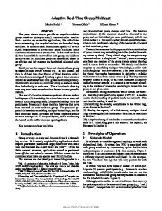
So far OM work essentially focussed on trees (e.g. [3]). In our work we consider several potential topologies, each of them having distinctive features (figure 1): bus: serial connection of all the nodes. tree: several kinds of trees are possible, like Shortest Path Trees (SPT) and Minimum Spanning Trees (MST). A SPT is per-source and in case of different sources, several SPT must be created which turns out to be costly. On the opposite a MST is source independent which is an asset with (n, m) group communications. ring: solution of the “traveling salesman problem”. The topology is source independent. star: all the nodes are connected around a central node. sun: a “sun” is a “star” with a non null diameter. It is therefore composed of an internal “ring” with peripheral “solar beams”. hybrid: hybrid topologies are possible that mix for instance the “tree” and “sun” solutions.
A Host-Based Multicast (HBM) Solution for Group Communications
tree topology
star topology
ring topology
sun topology
615
Fig. 1. Some possible overlay topologies.
average min/aver/max % of connected nodes
Choosing one of these topologies has serious impacts on robustness and performances. To analyze them we wrote a simulator. It takes in input a randomly and homogeneously distributed3 set of nn nodes. A topology solver is run, creating MST and Ring topologies. Each topology is then analyzed, failures introduced, and statistics gathered. Experiments are repeated 30 times for each nn.
90 80 70 60 50 40 30 20 0
20
40
60
80
100
number of nodes in topology
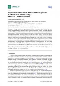
Fig. 2. Impacts of a single node failure on the connectivity of a MST.
Robustness in Front of a Node Failure. We simulated the impacts of a single node failure on the connectivity when the OM topology consists in a Minimum Spanning Tree (MST). Results are shown in Figure 2. For each value of nn, we successively turn down each node. We then measure the number of hosts still connected, cn, and plot the average {min/aver/max} values of cn. This experiment shows that with a Minimum Spanning Tree, a single node failure can easily partition the whole OM topology. If on average 62 to 84% of nodes remain connected, this value can be as low as 30%. On the contrary with a ring a single failure does not partition the topology. 3
In case of non-homogeneous node distributions, e.g. to simulate the impacts of a trans-atlantic line, the Traveling Salesman solver that creates the ring topology must be modified to take it into account. [9] page 445 gives such an algorithm.
V. Roca and A. El-Sayed
min/aver/max average delay (no unit)
616
2200 MST Ring
2000 1800 1600 1400 1200 1000 800 600 400 200 0
20
40 60 80 number of nodes in topology
100
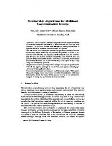
Fig. 3. Average delay for the Minimum Spanning Tree (MST) and Ring OM topologies.
Performances in Terms of Delay. [3] introduces several metrics to appreciate the quality of an overlay topology and which can be used during the topology creation process. In this section, we only focus on average group-shared delays [11]. This latter, for a given set of nn nodes and an OM topology, is given by: aver delay(nn, topo) = meanall
possible sources
(meanall
nodes�=source (delay(source
→ node)))
Not surprisingly above 15 nodes, a MST has a lower average delay that a ring. Yet the MST delay range is much higher and till 65 nodes, there are situations where the MST average delay is higher than the ring average delay.
4
Related Works
Yoid [6] is another OM scheme. If Yoid and HBM both rely on a RP, many differences exist. In particular Yoid creates a tree and uses a complex algorithm to avoid the creation of loops. Yoid also assumes that all nodes are stable. AMRoute [2] [8], developed for Adhoc networks, establishes an overlay topology for multicast communications. AMRoute distinguishes two kinds of topology: the mesh, a highly interconnected topology and the tree, a subset of the mesh, used for an efficient data delivery. If AMRoute does not try to evaluate interhost distances, the use of an Expending Ring Search (ERS) algorithm takes into account locality. If convenient in an Adhoc network where wireless communications enable diffusion, ERS is not feasible in the Internet unless multicast is already available! In NARADA [3] a mesh is first created and then a Reverse-Path Forwarding algorithm (e.g. DVMRP) is run on top of it to create a SPT per source. Many differences exist with HBM: there is no global view of the topology, it requires the use of an incremental mesh improvement technique, and per-node adaptation is not possible (a problem in case of highly heterogeneous nodes).
A Host-Based Multicast (HBM) Solution for Group Communications
617
In [7] an application layer routing architecture (ALR) is automatically created using an active network framework (ALAN). The topology creation process follows a hierarchical approach (for improved scalability) and relies on several metrics.
5
Conclusions
This work introduces an overlay multicast solution, HBM, which offers a group communication service to all hosts, even those located in a site where interdomain multicast is not available. It discusses the issues raised by the creation and the management of this overlay topology. We argue that a centralized solution, where the group membership is known by a Rendez-vous Point (RP), has many benefits over distributed solutions. Having a centralized topology management is simple (no coherency problem), efficient (the RP can create an optimal topology with respect to the distance database accuracy) and takes advantage of known node features during the topology creation process (e.g. to have stable transit nodes). We also argue that having additional redundant connections, even if it introduces additional traffic and loops, is important in front of the intrinsically fragile nature of an overlay topology.
References 1. K. Almeroth. The evolution of multicast: from the mbone to inter-domain multicast to internet2 deployment. IEEE Network, Special Issue on Multicasting, January 2000. 2. Bommaiah, A. McAuley, R. Talpade, and M. Liu. AMRoute: Adhoc multicast routing protocol, August 1998. work in progress; . 3. Y-H Chu, S. Rao, and H. Zhang. A case for end system multicast. In ACM SIGMETRICS, June 2000. 4. T. Cicic and H. Bryhni. Multicast-unicast re ector, January 2000. unpublished document, available at URL: http://www.i .uio.no/�tarikc. 5. C. Diot, B. Levine, B. Lyles, H. Kassem, and D. Balensiefen. Deployment issues for the ip multicast service and architecture. IEEE Network, pages 78{88, January 2000. 6. P. Francis. Yoid: extending the multicast internet architecture, September 1999. Unrefered Report; http://www.yallcast.com.
7. A. Ghosh, M. Fry, and J. Crowcroft. An architecture for application layer routing. In 2nd Int. Working Conf. on Active Networks (IWAN2000), October 2000. 8. M. Liu, R. Talpade, and A. McAuley. Amroute: Adhoc multicast routing protocol. Technical Report TR 99-1, CSHCN, 1999. 9. W. Press, S. Teukolsky, W. Vetterling, and B. Flannery. Numerical Recipes in C: the art of scienti c computing, second edition. Cambridge University Press, 1992. 10. V. Roca. Host Based Multicast: an alternative group communication service, July 2000. Tutorial presented at the \Ecole d'�et�e des r�eseaux hauts d�ebit et multim�edia" (RHDM'00). 11. L. Sahasrabuddhe and B. Mukherjee. Multicast routing algorithms and protocols: a tutorial. IEEE Network, pages 90{102, January 2000.
618
A
V. Roca and A. El-Sayed
An Algorithm for the Addition of Redundant Virtual Links (RVL)
This section describes a scheme to add RVL into the logical topology to decrease the probability of partitioned topology after a single node failure. The RP defines how many redundant links to create by using the following algorithm: // initialization acceptable_threshold = 0 // or another value in [0; 1[ AddRedundantLinks(virtual_topo, all_members_in_virtual_topo); // recursive solver AddRedundantLinks (topology, group) { if (proba(partitioned_topo, 1 failure)