ing, distribution of television data, or group management systems become important ... casting capabilities, due to a shared medium access method. However ... namely the internet protocol suite, Asynchronous Transfer. Mode (ATM) [15], and ...
An Error-Control Scheme for a Multicast Protocol Based on Round-Trip Time Calculations Daniel Bauer, Burkhard Stiller, Bernhard Plattner Swiss Federal Institute of Technology, Computer Engineering and Networks Laboratory Gloriastrasse 35, CH - 8092 Zürich, Switzerland [ bauer | stiller | plattner ] @ tik.ee.ethz.ch Abstract In contrast to traditional one-to-one applications, distributed multi-media applications are based on communication scenarios that involve huge, but often limited groups of participants. In general, tele-teaching and virtual reality scenarios require multicasting capabilities that have to deal with reliable data, e.g., simulation data, in addition to isochronous data, e.g., audio or video, that allow for losses depending on the compression technique or color tables. In particular, reliable control messages are needed for multicast signalling purposes. Existing networks have to be enhanced by integrating reliable multicast data transmission protocols to overcome this deficiency. The presented approach provides a network independent error-control scheme for a multicast protocol, offering a high stability in the local area, and an adaptable solution for metropolitan and wide area networks.
1
Introduction
As bandwidth increased and error rates decreased over the last few years, modern applications transmitting bandwidth consuming multi-media data over local and wide area networks became feasible. Nevertheless, errors due to buffer overflow and traffic congestion still occur. In addition, the variety of multi-media applications grows significantly due to a variety of user requirements. Especially, multicasting scenarios, such as tele-seminars, tele-teaching, distribution of television data, or group management systems become important in a highly distributed environment of universities and industry. Tele-seminars offer the possibility to invite speakers to a virtual colloquium. Teleteaching provides the potential of educating students in sparsely populated geographical regions, without establishing a complete new university. Another important field of applications is the support of reliable control protocols in multicast scenarios. In addition to user data transfers, signalling messages have to be distributed reliably to a huge, but limited number of receivers.
Multicasting capabilities to be offered within communication subsystems require a number of prerequisites.The underlying infrastructure in terms of networks has to be regarded. Some local area networks offer inherent broadcasting capabilities, due to a shared medium access method. However, reaching every single interconnected end-system on a network physically does not offer an adaptable solution for dedicated groups to be contacted. Therefore, the concept of multicasting has been invented. Addressing multicast groups and transmitting data to these groups require a certain type of error-control scheme and multicast routing [5]. Within wide areas, interconnected heterogeneous networks do not provide by themselves broadcast capabilities or multicasting. For that reason, multicast capabilities have to be provided explicitly by network or transport layer multicast protocols. Even more, as network layer protocols may offer multicasting functionality, e.g., the approach of IP multicast [4], more specifically the internet abstraction of hardware multicasting, these protocols do not provide required reliability in terms of packet delivery to a defined group of receivers. A solution for this lack of reliability leads to the design of error-control schemes on top of network layers, such as within transport protocols. The proposed error-control scheme is applied in different protocol architectures, namely the internet protocol suite, Asynchronous Transfer Mode (ATM) [15], and flexible protocol architectures, such as Da CaPo [14] or F-CSS [18]. Protocol architecture relevant details within end-systems have been considered carefully, to detect precise effects of error-control schemes on stability, scalability, and performance behavior unidirectional multipoint-to-multipoint multicasting. This paper is organized as follows. Based on related work, the design of an error-control scheme for multicast protocols is presented in Section 2. Within Section 3 the prototypical implementation on Sun SparcStations is discussed and performance evaluations are delineated for IP and ATM networks. Finally, a summary in Section 4 includes a brief explanation of future work.
To appear in 21st Conference on Local Computer Networks, October 13 - 16, 1996, Minneapolis, MN, U.S.A.
1.1
Multicast Transport Protocols
Reliable multicast is the task of correctly transporting data from a sender to many receivers. An initial classification of multicast error-control schemes distinguishes centralized and distributed error-control methods, a second one classifies four different types of error-control algorithms. In a centralized approach, a single host is responsible for assuring reliability for the entire multicast group. This host is normally the sender. It has to keep track of the status of all receivers and, if necessary, start error recovery. Control information is exchanged continuously between sender and receivers. The advantage of a centralized error-control is global knowledge. A failure of a link or a receiver is noticed by the controller. Unfortunately, centralized error-control limits scalability by two factors. Firstly, the controller has to store information about every member of the multicast group. Secondly, control information has to flow between the controller and receivers. This control information increases as the number of receivers increases and thus reduces scalability. Distributed error-control overcomes the drawback of the centralized approach of not being scalable. Error-control is done by each receiver independently. This leads to additional flexibility, since each receiver decides independently on how errors are to be recovered. Nevertheless, the disadvantage of the distributed approach is a loss of global knowledge. It is not possible to guarantee that data has been delivered correctly to all receivers, since if a link or a receiver runs out of order, the sender will not take notice of this problem. Error-control algorithms recover from packet loss and packet errors. Four categories of basic error-control algorithms for multicasting exist: • sender-initiated, • receiver-initiated, • hierarchical, and • forward error control. The sender-initiated approach is a straightforward extension of well-known unicast error-control methods, such as Go-back-N or selective retransmission. A single sender multicasts data packets to all receivers. Errors are detected by a combination of acknowledgments and timers. Senders keep track of state information for each receiver. Sender-initiated error-control schemes are centralized and provide global knowledge. If a packet for a particular receiver gets lost, the sender retransmits it. The sender-initiated approach has some major drawbacks. Firstly, it does not scale well to large number of participants. Since every participant has to acknowledge received packets, the
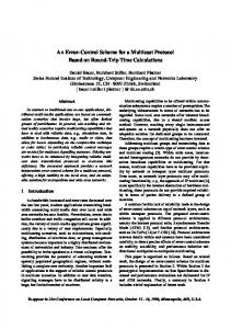
sender receives a great number of acknowledges almost simultaneously. This effect is called “packet implosion” and it can cause a breakdown of the sender. Even if the sender can cope with every acknowledgment, it has to keep status information for every receiver. Therefore, memory and CPU (Central Processing Unit) usage increases as the number of receivers grows. Hence, sender-initiated errorcontrol is applicable for a small number of receivers only. Sender-initiated error-control can be extended by a hierarchical scheme (cf. Figure 1). Participants are arranged in a tree-like hierarchy defining the sender as root. There are two possibilities to perform hierarchic error-control. In the first variant, the sender multicasts data packets to its children. Children acknowledge data and forward them to their children in turn, where the process is repeated. This method offers better scalability compared to direct sender-initiated error-control. However, end-to-end error-control is not performed. If packets are corrupted or lost inside a node after they have been acknowledged, this situation can not be recovered since the sender has discarded them. In the second approach, after reception of data, each node propagates packets to its children and waits for an acknowledgment. Only if all acknowledgments have arrived, the node acknowledges this packet to its parent. End-to-end error-control and scalability can be achieved using this approach, but only to the cost of a relative high acknowledgment delay.
Figure 1. Hierarchical Error Control Scheme Receiver-initiated error-control overcomes scalability limitations of sender-initiated methods [16]. Receivers are responsible for detecting errors and requesting retransmissions of corrupted or lost packets. Lost packets are detected using sequence numbers. Each packet contains a sequence number. If a receiver detects a gap in received sequence numbers, it requests lost packets from the sender or possibly from other receivers by sending a retransmission request (RRQ). If the RRQ is multicast to the group, other receivers that experienced an identical packet loss will recognize it and suppress their RRQ. In addition to user data packets, the sender issues periodically so called keep-alive
packets. Keep-alive packets contain the last valid sequence number. This enables receivers to detect lost packets, even if currently the sender does not want to transmit further data packets. In the receiver-initiated approach, the load of senders is reduced. Therefore, this approach scales better. However, receiver-initiated error-control suffers from the drawbacks of a distributed error-control. Another problem arises concerning the transmission of keep-alive packets. On one hand, if keep-alive packets are sent very often, the overhead of the error-control protocol is significant. However, on the other hand, if keep-alive packets are sent rarely, the delay for detecting errors is increased considerably. Either sender- and receiver-initiated approaches require the retransmission of erroneous packets, which introduces delay. For audio- and video-streams sent over networks with a high bandwidth-delay product, a retransmission delay is unacceptable. Forward error correction (FEC) schemes overcome this problem. Errors are corrected by introducing redundancy into the originally sent packet stream. Depending on the kind of redundancy, bit errors and one or several continuous packet losses can be corrected. Error correction takes place at receiver sides. Since no feedback exists between sender and receivers, FEC is completely scalable concerning the number of receivers. However, FEC increases the need for extra bandwidth according to added overhead in terms of explicit redundant data. Forward error correction does not completely avoid delay. If a packet gets lost, the receiver might have to wait for further packets, until suitable information is available to reconstruct the missing packet. Furthermore, in extreme cases it is not possible to recover from packet losses due to burst errors. There is a trade-off between redundancy that is introduced and the number of errors that can be corrected as well as the delay that is needed to recover from an error. As with receiver-initiated error-control, FEC is distributed and does not allow for sender-based detection, whether data has been received by all participants correctly.
1.2
Related Work
In this Subsection, a selected number of designs and implementations of error-control mechanisms is presented briefly. These mechanisms do sometimes follow a hybrid approach and are often part of full-fledged multicast transport protocols. Early work in the area of multicast error-control used sender-initiated approaches based on traditional unicast Go-back-N protocols [12], [7]. As throughput efficiency of these protocols is not scalable with the number of receivers, these protocols are best suited for situations where a centralized control for small multicast groups is needed.
The Multicast Transport Protocol (MTP) [1] offers flow-controlled, reliable, and total ordered multicasting. Ordering is implemented using a token scheme. Reliability is ensured using the receiver-initiated error-control approach. The set of communicating processes in MTP is called a web. A web consists of consumers that only receive data, of producers that send and receive data, and of a single web master that is responsible for administration, flow-control, and ordering of messages. Producers that wish to send data have to request a token from the master. While holding the token, the producer is allowed to send a limited amount of data. The master revokes the token after a fixed amount of time. Consumers detect errors in the data stream using the receiver-initiated error-control approach. Packets are requested from the producer by sending a RRQ with a list of missed packets. If no producer is active, the master enters a hibernating state and starts to send keepalive packets at a fixed rate. MTP, however, is not generally applicable to all applications, since only a throughput of about 1.5 Mbit/s can be reached [17]. The multicast error-control proposed in [6] is an extension of the receiver-initiated error-control approach. The protocol is enhanced to support efficiently a wide range of group sizes over different topologies and link bandwidths. If a packet gets lost, the member closest to the sender first requests the lost packet. Requests and retransmissions are multicast to the group. Receivers that encounter exactly the same packet loss will suppress a retransmission request. Furthermore, packet retransmission can be done by any group member that holds a copy of the packet. The error recovery scheme used in this approach is designed for networks with inherent multipoint-to-multipoint capabilities such as IP multicasting, which makes it difficult to adapt it for different networks such as ATM. “Log-Based Receiver-Reliable Multicast” is also an enhancement of the basic receiver-initiated error-control approach [9]. Scalability is extended by so called “logging servers”, which store packets for retransmissions. Large multicast groups are equipped with several logging servers. Receivers experiencing packet loss request a retransmission from their nearest logging server. A further enhancement concerns the transmission of keep-alive packets. These packets are transmitted in predictable, exponential increasing intervals. Therefore, bandwidth savings and at the same time delay reductions – needed for the detection of lost packets – are achieved. The log-based multicasting protocol has been designed to run on top of IP multicasting. It makes specific use of the IP time-to-live (TTL) field whose semantics is not available in other multicast capable networks. Forward error correction has been developed for networks with high bandwidth-delay products. FEC trades bandwidth for delay in order to reduce the error rate. FEC
is suitable for applications being delay sensitive, but can cope with some losses [2]. In [3], a framework for multipoint multimedia services is presented. The error-control mechanism used in the framework is based on a hierarchical approach. So called “group communication servers” are placed inside the network, where a reliable delivery to a subset of receivers is provided. This approach needs to supply networks explicitly with “group communication servers”. A hybrid mechanism consisting of receiver-initiated and hierarchic error-control is presented in [8]. Receivers are divided into so called “local groups”. Local groups form a tree-like hierarchy, while the sender forms the root. A sender multicasts packets to all receivers. Packet errors are recovered firstly inside the group using a receiver-initiated approach. Each local group is managed by a local group controller, which processes retransmission requests of group members. Periodically, the sender requests status messages from all local group controllers. These status messages also contain retransmission requests for packets missing by the local group. This approach combines the advantages of hierarchical and receiver-initiated error-control at the cost of a complex protocol.
2
Design of an Error-Control Scheme for Multicast Protocols
Receiver-initiated multicast protocols are scalable in principle, due to the fact that packet implosion does not happen since a single sender does not receive acknowledgments from each receiver and for each packet. In addition, the design for a multipoint-to-multipoint error-control scheme based on round-trip time (RTT) calculations has been chosen to provide a sufficient mechanism defining time-out values. Receivers detect packet loss and out of order deliveries of packets. Sequence numbers are used to identify packets, especially missing ones at receiver sides. Additionally, senders issue status messages in a predictable fashion, indicating the currently used sequence number and allowing receivers to detect packet losses, even if the sender pauses transmission of data packets on an existing association.
2.1
scheme defines a reliable multipoint-to-multipoint protocol including the following functionalities.
• • •
•
•
• • •
(a) Reliability issues: The out of order delivery of packets at a receiver side is encountered due to sequence numbering. Duplicated packets at a receiver side are identified by duplicated sequence numbers and discarded. To handle packet transmissions of a pausing sender, the sender issues predictable log-based status packets that indicate the last sent and used sequence number to allow receivers for the uniquely identification of missing packets. Joining senders are identified by a specific sequence numbering range. (b) Throughput and utilization issues: A detected packet loss at a receiver side does not lead to an immediate retransmission request (RRQ), but after a specified time-out interval a RRQ will be issued if the missing packet has not arrived; in case of ATM, this time-out value equals zero due to an already provided ordered delivery of data. A receiver bundles several RRQs for multiple missing packets into a single RRQ. Every RRQ is unicast to the original sender directly, which offers an independency of the network topology. A sender multicasts only once to a number of RRQs, including identical missing sequence numbers from different receivers and arriving within a parametrizable time interval, since a single retransmission of this packet satisfies all receiver needs. This leads to a reduction of packets to be retransmitted.
These features are provided by mechanisms, based on a specific calculation of the round-trip time as explained within Subsection 2.2 and supported by a dedicated packet format (cf. Subsection 2.3). Regular range for data packets Range for data packets of already active senders of joining senders
Features of the Error-Control Scheme
Two considered important criteria for receiver-initiated multicast protocols are (a) to support reliability and (b) to increase throughput and utilization of the underlying network by reducing administrative network traffic. Therefore, eight features of the multicast protocol to provide an error-control scheme have been designed, taking into account that an IP or ATM multicast capable network layer protocol is provided. The resulting multicast error-control
0
1
2
m-1 m
m+1
n–1
Figure 2. Sequence Number Scheme In general, every sender provides sequence numbers of 4 Byte length, ranging from 0 up to m-1 (cf. Figure 2). Receivers that do not receive a packet within a certain
period of time due to packet loss, issue a retransmission request (RRQ) including a sequence number of the missing packet. This RRQ is unicast back to the sender or ATM multicast server (cf. Subsection 3.1), since only they are responsible for handling negative acknowledgments. Joining senders to a group of receivers always start their transmission of packets with the sequence number m in the upper reserved sequence number range, where n-m-1 equals a small configurable number, such as 20. Additionally transmitted packets are marked with increased sequence numbers, until reaching the upper limit n–1. Afterwards, regular sequence numbers are used beginning from 0. Applying this new idea [13], receivers are aware of initial sequence numbers greater than m for joining senders and, therefore, can distinguish between the first packet transmitted or any other one afterwards. An initial synchronization between newly joining senders and already existing receivers is reached. Setting the right value for n-m-1 depends on the strategic decision on the size of provided back-log buffer space. In case of losing every packet in the range n-m -1 the regular start of receiving packets from sequence number 0 takes place, determining a late join operation. Joining receivers accept any sequence number as the starting point of their life-time within a certain group. In this case, RRQs will not be issued for packet sequence numbers smaller than the one first received. If a new receiver detects a certain sequence number s, where s ∈ {m, ..., n–1}, all missing packets k, with m < k < s, if existing, are negatively acknowledged and requested. This mechanism is feasible and used for setting-up a new association, since the receiver knows that a new sender has been introduced in about the same time itself has joined the group. The tear-down phase for receivers is defined by leaving the group and no further packets will be received any more. A leaving sender explicitly has to inform receivers that it leaves the association. Therefore, exit packets are issued from the sender. If an exit packet gets lost, a time-out at the receivers side occurs (normally in the range of 5 minutes) and the receiver leaves the association. In a period of no application activity within an existing association, receivers per se would not be able to detect packet losses any more. Therefore, the sender issues status messages (keep-alive packets) in a predictable fashion. The status message including the last used sequence number and allow the receivers to identify lost packets explicitly. Status messages are sent in exponential increasing intervals in order to keep bandwidth consumption to a minimum. This mechanism has been applied from [9]. Lost keep-alive packets are treated similarly using time-outs as exit packets within the tear-down phase. If necessary, grouping of RRQs may be done at receiver and sender side. For a receiver, consecutively missing
packets {i, i+1, ... , i+j } and i, j > 0 may be identified by a combined RRQ requesting exactly that range. Senders have to reply on these RRQs and, in turn, may group to be retransmitted packets as well. Incoming RRQs at a sender may be ignored if corresponding retransmissions have been started before the retransmitted packet arrived at the requesting receiver. This assumed packet arrival time is based on the estimation of the average round-trip time (RTT) between the sender and receivers. Otherwise, the requested packet has to be retransmitted. Therefore, a sender groups incoming RRQs according to requested sequence numbers and timing information, which is based on the RTT, in approximation twice the amount of the transmission delay between sender and receiver.
2.2
Time-Out and RTT Calculations
Issuing RRQs is based on the time-out value for missing packets. In addition, a well suited value shall not fall short of the round-trip time (RTT) between sender and receiver. Therefore, the back-off solution from the Transmission Control Protocol (TCP) [11] for defining an acceptable time-out value is applied. Nevertheless, in contrast to TCP, the back-off solution is deployed within the multicast error-control scheme for every RRQ separately, while the initial RRQ is issued by a receiver after the expiration of 4 * RTT. RTT is defined as the period of time between sending a packet and receiving a directly related reply without considering a processing delay in a receiver. Since arrivals of packets may be acknowledged, RTT is calculated as the difference between the time of arrival of a previous RRQ and the time of sending a successive data packet, subtracting the processing delay tout, a receiver has utilized for the RRQ (cf. Figure 3.). This RTT is more precise than a possible time interval between packet n and RRQ_n, since RRQ_n is definitively the corresponding reply on packet n+1, knowing that the receiver lacks packet n. In addition, due to relative timing information at sender and receiver sides, a global time basis is not required, because the sender by itself keeps track of sending times and subtracts a relative time (tout as a length of time) only. The problem with this calculation of RTT lies in the inaccurate value per acknowledging transaction, based on variable delays for packets and corresponding acknowledgments. Therefore, a suitable adaptation of RTT over time, e.g., as for TCP, is applied according to the following formula [11]: RTT = (a * old_RTT) + (1 - a) * measured_RTT; with 0 < a < 1
Within the multicast situation, in principal an identical calculation can be performed. However, if the original sender issues a packet to a group of receivers and two receivers issue a RRQ, the calculation of RTT happens, and
the sender retransmits the packet including an averaged RTT over two receivers and ignores further request messages. Therefore, based on the retransmitted packet from a sender a single receiver only within a multicast group may determine the entirely correct RTT, all others do vary slightly from the real RTT depending on their location within the network. The solution to this problem is covered by a mechanism to add a reference to a retransmitted packet, which request has been answered. Every retransmission leads to a correct calculation of RTT for the requesting receiver. Receiver
Sender n n+1
tout
RTT + tout RRQ_n
Figure 3. Calculation of the Round-Trip Time Still, the first request will be answered only, to reduce the amount of linear increasing retransmissions per additional receiver of the same packet for multiple receivers. Applying the approach of attaching time stamps per packet does not provide a feasible solution according to problems of globally synchronized clocks. Therefore, a sender-based calculation is added. The sender calculates one RTT on a set of receivers as an average value for every available one and includes this average value in every packet to be transmitted. The quality of this RTT depends on the variance of single receiver RTTs. Resembling variances lead to an almost exact RTT value, while diverse variances deliver a correct RTT value to a small number of receivers only. Nevertheless, this mechanism does not affect the error-control scheme of the multicast protocol. Only if packet losses occur, RTT calculations may be performed. If no retransmissions have taken place, an initial value will be used. Assuming this value as an estimation for the correct RTT, an upper bound for an incoming request at a sender side exists. Receivers are informed on the current RTT via retransmitted packets. Therefore, the time-out value can be set accordingly. However, this specific value may be inaccurate for a dedicated receiver due to the averaging behavior of the sender. On one hand, a small RTT leads to multiple retries for issuing an identical RRQ, before the first RRQ reaches the sender. On the other hand, a huge RTT causes to wait for issuing
the first RRQ. Therefore, the back-off solution is applied to enlarge and diminish respectively the time-out, which in turn adjusts the RTT calculation at the sender as desired. Finally, the time needed to compute averaged RTTs over a set of receivers is in the order of µs compared to handling the protocol issues in the order of milliseconds.
2.3
Packet Format of the Multicast Protocol
The general structure of the designed multicast protocol packet is depicted in Figure 4. The simple packet header includes 10 Byte of multicast information only. Packet field P defines the packet type (1 Byte) as data, exit, or keep-alive. S identifies the sequence number by 4 Byte length (cf. Subsection 2.1 above). The field R (1 Byte) counts the number of retransmissions per packet, uniquely identified by S. Timing information is added in field T (4 Byte) for the round-trip time calculated by the sender or for processing delay tout within a receiver. Finally, field D defines the maximum number of user data per packet, which comprises a number of 65,506 Byte for UDP (User Datagram Protocol) or 65,518 Byte for the ATM Adaptation Layer 5 (AAL 5) [15]. This number D is derived from the maximum message transfer unit of the underlying protocol (UDP Header length of 20 Byte or AAL 5 Header length of 8 Byte plus mandatory padding for 8 Byte alignments), subtracting 10 Byte multicast protocol header consisting of fields P, S, R, and T. Timing Information
Sequence Number P Packet Type
S
R
T
Retransmission Counter
D User Data
Figure 4. Multicast Protocol Packet Format
•
•
•
Five packet types are distinguished: The regular data packet and a retransmitted data packet differ in field R only. While in the original packet R equals zero, the retransmitted packet includes in R the current number of retransmissions for this packet. T identifies the currently valid RTT. The retransmission request packet (RRQ) specifies within P the type RRQ and within T the processing delay tout. The data part contains the sequence numbers of the packets that are requested to be retransmitted. A keep-alive packet is identified by the packet type keep-alive (P), a sequence number of the upcoming data packet (S), the number of already sent status packets (R) including an identical sequence number, and the current sender-calculated round-trip time (T).
•
Finally, the exit packet includes the final sequence number S of a leaving sender and the current RTT within the T field. These packets will be encapsulated within an UDP packet or AAL 5 frame depending on the used network infrastructure.
3
Implementation and Evaluation
A prototypical implementation of the multicast protocol has been carried out in order to practically evaluate and test the error-control scheme. The prototype runs on SUN Sparc stations and uses IP and ATM multicasting. The implementation is located in the UNIX user space, where it is linked to a test application. Figure 5 presents an overview of the implementation architecture. User Space
Application Multicast Error-Control IP-Multicast Conversion
ATM-Multicast Conversion
Group Management Protocol (IGMP) [4] is used for signalling multicast group membership changes to the multicast routers. For the tests, IP multicasting runs over an IEEE 802.3 LAN (Ethernet). ATM with its inherent multicast capabilities is accessible using a proprietary interface, similar to the Berkeley sockets. It offers direct access to the ATM Adaptation Layer 5 (AAL 5), which is based on the ATM cell level and optical TAXI or OC3-c interfaces.
3.1
IP- and ATM-Multicast Conversion
ATM multicasting differs from IP multicasting in several ways. The task of the multicast conversion layer is to provide a unified view, such that the error-control layer does not have to be aware whether IP or ATM multicasting is used. IP multicasting offers unreliable multipoint-tomultipoint data transfer, which is the functionality needed by the multicast error-control layer. Therefore, the IP-multicast conversion layer is almost empty, including some system calls only. R
R
R
UDP
Kernel Space
IGMP IP / IP Multicasting
ATM Signaling AAL 5
IEEE 802.2
ATM Cell Level
IEEE 802.3
ATM TAXI/OC3-c
S
Topology above Conversion Layer
R
Figure 5. Implementation Architecture of the Prototype The architecture of the prototype uses a layered approach. The tasks of the individual layers are as follows: • The “Application” layer of the prototype is used for generating packets and measuring error-control parameters. The application implements a fixed-rate flowcontrol. • The “Multicast Error-Control” layer implements the error-control scheme as designed and described entirely in Section 2. • Both multicast conversion layers, “IP-Multicast Conversion” and “ATM-Multicast Conversion”, form an interface to IP and ATM multicasting respectively. They offer a unified multipoint-to-multipoint abstraction that is used by the error-control layer. Details are described in the following Subsection. The implementation accesses the IP multicasting kernel functions using the Berkeley socket interface over the User Datagram Protocol (UDP). Inside the kernel, the Internet
S
R
R
MCS
S
S
Topology below Conversion Layer Data connection with bandwidth guarantees Bidirectional control connection without bandwidth guarantees S
Sender
R
Receiver
MCS
Multicast Server
Figure 6. ATM Multicast Conversion Current signalling protocols used in ATM provide a simplex point-to-multipoint service only. Multicasting is strictly sender-oriented. A sender can build a multicast
Number of RRQs 242
40 20
10
20
30
40
50
60
70
80
90
100
>100
RTT [ms]
Figure 7. Distribution of RTTs delivery tree by adding ATM endpoint addresses to a connection. Furthermore, ATM multicasting is uni-directional. User data flows from the root (sender) of the tree to all leaves (receivers) only. The ATM-multicast conversion layer extends this basic point-to-multipoint service to a multipoint-to-multipoint service by mapping the multipoint-to-multipoint topology to several point-tomultipoint connections [10]. Besides the conversion layer at each endsystem, an ATM multicast server is needed for distributing control information and managing multipoint connections (cf. Figure 6). Since a single multipoint-tomultipoint connection is directly mapped onto several point-to-multipoint connections, bandwidth guarantees of ATM still can be used. Mapping the topology is done by building a point-tomultipoint tree for each sender. The critical operation is the operation “join“, which is different for senders and receivers. Whenever a sender joins, the point-to-multipoint tree has to be established. Therefore, the endpoint addresses of every receiver have to be transferred to the new sender, which builds the multicast tree. If a receiver joins, this receivers address has to be sent to all existing senders, which in turn add this address to the multicast tree. The distribution of addresses and the relaying of control information is done by the ATM multicast server. The ATM multicast server listens to a well-known address. New participants initially establish a bi-directional control connection to this server and register themselves either as senders or receivers. The control connection is also used by receivers to return RRQs to senders. The use of the ATM conversion layer is not limited to the RTT-based error control scheme.
3.2
Performance Evaluations
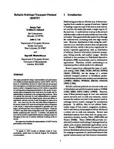
The prototype has been tested with IP-multicast in the first place, which has been carried out over IEEE 802.3 networks. A first test involved two IEEE 802.3 subnetworks that had been connected with two multicast routers “mrouted v3.8”, running on UNIX workstations. Each sub-
net contained a sender and a receiver. The two senders transmitted a total number of 170,000 packets during 7 days, while packet sizes ranged from 1 to 10 kByte. In addition to these test machines, 12 productive workstations have been attached to the networks, which where producing real-world background traffic from applications, such as NFS (Network File Service), WWW (World Wide Web), telnet, FTP (File Transfer Protocol), or e-mail. This test delivered figures on round-trip times and the number of necessary retransmissions. Figure 7 depicts the distribution of measured round-trip-times based on the number of retransmission requests (RRQ). As it can be seen, most RTTs were quite low. However, the variance of the RTTs is large, with the smallest RTT being almost 200 times smaller than the largest one. Differences in RTTs are caused by the multicast routers, which have been running on workstations that were also used by other applications. This long-time test demonstrated that about 1% of the packets had been lost or corrupted. For most of these packets, a single RRQ has been sufficient. 95% of errors have been recovered by two retransmission requests. Interesting enough, packet errors only occurred for packets that had to be forwarded by the multicast router. Additionally, the throughput of the protocol has been measured on a IEEE 802.3 subnet without background traffic. A sender transmitted 5,000 fixed-sized packets of 1, 10, and 32 kByte to 1, 2, 4, 8 and 10 receivers. Since a ratebased flow-control is used, the throughput is affected only by the number of RRQs a sender has to process. Table 1 determines measured throughputs, which are presented in MBit/s, based on the packet size in kByte. The number of received RRQs for packet sizes of 1, 10, and 32 kByte, as well as the actual retransmitted packets are indicated in Table 2. As it can be seen, the packet error rate was quite low. In the worst case, an overall of 2.2% of the packets had to be retransmitted. The table also depicts the positive effect on grouping retransmission requests, e.g., in the column with 8 receivers 111 RRQs for 10 kByte packets have been sent, while 91 packets have been retrans-
# Receivers
1
2
4
8
10
1 kByte
0.82
0.82
0.82
0.82
0.82
10 kByte
8.19
8.19
8.18
8.14
8.16
32 kByte
8.72
8.70
8.71
8.72
8.60
Table 1. Throughput in Mbit/s over IP mitted only. This leads in this case to an reduction of almost 20% for retransmitted packets. # Receivers
1
2
4
8
10
# RRQ (1 kByte)
0
2
36
7
6
# Retransmits
0
2
36
7
6
# RRQ (10 kByte)
1
8
7
111
58
# Retransmits
1
8
7
91
58
# RRQ (32 kByte)
0
30
21
18
40
# Retransmits
0
29
20
17
37
Table 2. Retransmission Requests (RRQs) and Retransmitted Packets The throughput measurements over ATM resulted in performance values presented in Table 3. A single sender transmitted packets at a fixed rate to 1, 2, 4, 8, and 10 receivers. The rate has been chosen to avoid swamping the slowest receiver. For each set of receivers, 10,000 packets have been transmitted. Due to a limitation of the ATM device driver, the packet size was limited to a maximum of 9 kByte. During these measurements, no packets have been lost, therefore, no figures on retransmission requests and retransmitted packets are necessary. # Receivers
1
2
4
8
10
1 kByte
8.6
8.5
8.4
8.4
8.5
9 kByte
42.4
42.3
42.3
42.7
42.7
is satisfactory. In case of ATM-networks, the use of T 3 trunks is possible without any protocol bottleneck, since the performance numbers indicate a safe reserve. Furthermore, the evaluation of the prototype also demonstrated a suitable scalability of the error-control scheme and the multicast protocol for a local area environment. There are two tracks to be considered for future work. Firstly, the protocol has to be tested in a metropolitan/wide area environment, where the variance in the round-trip time will be significantly larger than in the tested local area. Secondly, the protocol has to be integrated into real-world applications as mentioned in Section 1. As a first step, an integration of the protocol in the flexible protocol architecture Da CaPo will take place, where it is used for a variety of applications. As a subsequent step, the suitability of the protocol for real-time multi-media data in a local and metropolitan area ATM-network has to be evaluated. Real-time multi-media data is delay sensitive. However, retransmissions of lost packets are still feasible, considering low retransmission times in local area ATM-networks. Receivers selectively request retransmissions based on the maximum delay allowed and the calculated round-trip time. Of course, this variation of the multicast protocol is not completely reliable, however, it could be used to decrease the loss rate for real-time multi-media data.
Acknowledgments The authors are grateful to acknowledge M. Büchi, F. Iten, and G. Nigg for implementing the multicast protocol in addition to the error-control scheme. Additionally, thanks are addressed to L. Mathy for commenting on an earlier version of this paper.
References [1]
S.M. Armstrong, A.O. Freier, K. Marzullo: Multicast Transport Protocol; RFC 1301, February 1992.
[2]
E. W. Biersack: Performance Evaluation of Forward Error Correction in ATM Networks; ACM Computer Communications Review, Vol. 22, No. 4, October 1992, pp 248 – 257.
[3]
G. Carle, J. Schiller, C. Schmidt: Suport for High-Performance Multipoint Multimedia Services; International COST 237 Workshop, Vienna, Austria, November 13 – 15, 1994, Eds. D. Hutchinson, A. Danthine, H. Leopold, G. Coulson, Lecture Notes in Computer Science, No. 882, Springer, Berlin, Germany, 1994, pp 219 – 240.
[4]
S. E. Deering: Host Extensions for IP Multicasting; RFC 1112, August 1989.
Table 3. Throughput in Mbit/s over ATM
4
Summary and Future Work
The presented receiver-initiated multicast error-control mechanism is based on round-trip time calculations. This error-control mechanism is identically applicable to both IP multicasting and ATM multicasting. A prototypical implementation reflected the usability of this approach. As the measurements indicate, the performance of the protocol
[5]
[6]
[7]
[8]
[9]
S. E. Deering: Multicast Routing in a Datagram Internetwork; Ph.D. Thesis, Stanford University, California, U.S.A., December 1991.
[12] K. Mase, T. Takenaka, H. Yamamoto, M. Shinohara: Go-
S. Floyd, J. Van Jacobson, S. McCanne, C.-G. Liu, L. Zhang: A Reliable Multicast Framework for LightWeight Sessions and Application Layer Framing; ACM Computer Communications Review, Vol. 25, No. 5, August 1995, pp 342 – 356.
tions, Vol. com-31, No. 4, April 1983, pp 583 – 489.
I.S. Gopal, J. M. Jaffe: Point-to-Multipoint Communication Over Broadcast Links; IEEE Transactions on Communications, Vol. com-32, No. 9, September 1984, pp 1034 – 1044. M. Hofmann: A Generic Concept for Large-Scale Multicast; International Zürich Seminar, February 21 – 23, 1996, Ed. B. Plattner, Lecture Notes on Computer Science, No. 1044, Springer, Berlin, Germany, 1996, pp 95 – 106. H. W. Holbrook, S. K. Singhal, D. R. Cheriton: Log-Based
Receiver-Reliable Multicast for Distributed Interactive Simulation; ACM Computer Communications Review, Vol. 25, No. 5, August 1995, pp 328 – 341. [10] F. Iten, M. Büchi: Mehrpunkt-zu-Mehrpunkt Multicasting über ATM; Students Work, TIK, ETH Zürich, Switzerland, March 1996. [11] V. Jacobson: Congestion Avoidance and Control; ACM Computer Communications Review, Vol. 18, No. 4, August 1988, pp 314 – 329.
Back-N ARQ Schemes for Point-to-Multipoint Satellite Communications; IEEE Transactions on Communica[13] G. Nigg: Multicast Module für Da CaPo; Diploma Thesis, TIK, ETH Zürich, Switzerland, March 1996. [14] T. Plagemann, B. Plattner, M. Vogt, T. Walter: A Model for Dynamic Configuration of Light-Weight Protocols; IEEE 3rd Workshop on Future Trends of Distributed Systems, Taipeh, Taiwan, April 14 – 16, 1992, pp 100 – 106. [15] M. de Prycker: Asynchronous Transfer Mode – Solution for Broadband ISDN; 3rd edition, Prentice Hall, Englewood Cliffs, New Jersey, U.S.A., 1995. [16] S. Pingali, D. Towsley, J. Kurose: A Comparison of
Sender-Initiated and Receiver-Initiated Reliable Multicast Protocols; ACM SIGMETRICS, Vol. 22, No. 5, May 1994, pp 221 – 230. [17] F. Sennrat, O. Hermanns: Performance Investigations of the MTP Multicast Transport Protocol; PROMS’95, Second Workshop on Protocols for Multimedia Systems, Salzburg, Austria, October 9 – 12, 1995, pp 382 – 392. [18] M. Zitterbart, B. Stiller, A. Tantawy: A Model for Flexible High-Performance Communication Subsystems; IEEE Journal on Selected Areas in Communications, Vol. 11, No. 4, May 1993, pp 507 – 518.