A hybrid architecture for autonomous navigation in dynamic environments C. Urdiales, E.J. Perez and F. Sandoval Dpt. Tecnolog¶³a Electr¶o nica University of M¶a laga Email:
[email protected] ABSTRACT This paper presents a hybrid architecture for autonomous robot navigation. It includes a deliberative layer that hierarchically extracts a global path from a geometrical-topological model of the environment. This path is decomposed into a set of partial goals. Then, a new case-based reasoning based reactive layer capable of learning new local navigation strategies moves from each partial goal to the next. The architecture has been succesfully tested in real dynamic environments. KEY WORDS deliberative planning, reactive navigation, hybrid layered architecture, case-based reasoning
1
Introduction
Navigation can be de¯ned as the act of ¯nding and tracking a safe path to a de¯ned goal. Autonomous robotic navigation has been widely studied in the last decades. Proposed techniques range from highlevel planning schemes to reactive control strategies. High level planning methods require extensive world knowledge so the robot can act in a predictable e±cient way. These methods typically rely in a classic sense ¡ model ¡ plan ¡ act cycle known as horizontal decomposition [8]. Deliberative schemes are often criticized for their inability to react rapidly. Also, since they strongly depend on a world model, they are not suitable to operate in partially or totally unknown environments nor in signi¯cantly dynamic ones [1]. Reactive control methods rely on directly coupling sensors and actuators [3]. Combinations of reactive behaviours return emergent actions. Unlike classic deliberative systems, reactive schemes can easily deal with several sensors and goals. Besides, they are °exible and quite robust against sensor errors and noise. Unfortunately, emerging behaviours may be very unpredictable and, in some cases, non-e±cient. Reactive systems are also prone to fall into local traps. Hybrid systems combine deliberative and reactive schemes to achieve a better performance. Usually, low level control is performed in a reactive way whereas high level processing follows a deliberative pattern. Hybrid systems are supported
J. V¶azquez-Salceda Institute of Information and Computing Sciences Utrecht University email:
[email protected] by biological evidence [1] and they can achieve e±cient navigation in dynamic and totally or partially unknown environments. This paper presents a hybrid scheme for autonomous navigation in dynamic environments. Our scheme is based on decomposing tasks in layers as proposed by Brooks [3]. High level layers reason about the environment and propose a global path to the goal. Low level layers are in charge of safely reaching that goal according to guidelines proposed by the high level layers. Section 2 presents a brief global description of the system, outlining the di®erences between this proposal and previous ones by the authors. Section 3 presents our high level path planning technique plus a world modelling technique. Section 4 presents a new CBR based reactive layer. The main novelty of the proposed architecture is this trainable reactive layer and its integration into the hybrid architecture. Section 5 presents experiments and results for the complete hybrid structure. Finally section 6 presents conclusions and future work.
2
Proposed hybrid scheme
As aforementioned, hybrid systems combine deliberative and reactive schemes in order achieve a better performance. Usually, low level control is performed in a reactive way whereas high level processing follows a deliberative pattern. The main concern when building a hybrid scheme is to ¯nd the appropiate boundary for the subdivision of functionality [1]. We propose an advising scheme where navigation is performed in a bottom-up way: the sucessively combined responses of the low level layer provide a global goal-reaching navigation behaviour. This hybrid structure is particularly interesting for dynamic and partially explored environments because the system can inmediately react in an e±cient way to unexpected obstacles and high level planning avoid local minima by providing intermediate goals for the low level layer. Our hybrid navigation architecture basically consists of four layers (Fig. 1). First, a geometrical modelling layer uses the on-board sensors to construct and update an evidence grid as proposed in [12]. Then, the
both updated and processed in a fast way; and iv) the local navigation layer may work even when the output from higher level layers is outdated. Thus, the robot does not need to stop when a given path needs to be recalculated because of unexpected obstacles in the way. This architecture has been succesfully tested in real indoor environments using a Pioneer robot.
3
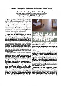
Figure 1. Proposed hybrid scheme.
grid is processed by the topological modelling layer to obtain a topological map proposed by the authors in [17]. Both the geometrical and topological maps are updated as often as possible so that reasoning is always performed over the most recent model available. Our deliberative layer is known as route planner. It is in charge of calculating an e±cient global path free of obstacles between a departure and an arrival point as proposed in [17]. This layer is triggered each time a new goal is proposed but also when the topological map su®ers signi¯cant changes in areas where the robot is operating. It must be noted that this layer is quite fast. Hence, it is not necessary to stop the robot while calculating a new deliberative route. Instead, navigation is reactively handed until a new goal is provided. Paths calculated at topological level can be inmediately propagated into path regions at metric level. These regions were the output of the deliberative layer in our previous scheme [17]. However, in the current one we thin the region into a path and decompose that path into segments which can be tracked with minimum curvature changes. The joints of these segments become partial goals to the robot and are the output of the route planner. Instead of tracking the path in a deliberative way as we did in [16], our local navigation layer relies on a reactive scheme to move safely between consecutive partial goals. A ¯rst version of this architecture was proposed in [17]. However, in [17] the reactive layer was based on potential ¯elds. In this work, we have developed a new reactive layer based on CBR (Case-Based Reasoning). Its advantages with respect to potential ¯elds are described in section 4. The proposed hybrid architecture works in an ef¯cient way because: i) the deliberative layer proposes e±cient paths to arrive to a goal; ii) these paths are tracked in a fast reactive way to handle sensor errors and unexpected situations; iii) the environment is represented at two hierarchical levels so that it can be
Deliberative path planning
Deliberative navigation algorithms rely on world models either provided a priori or built by means of the onboard sensors. These models can be processed by any classic planning algorithm to calculate a safe tra jectory. Representations of the environment are usually built according either to the metric or the topological paradigm. Metric representations, most typically evidence grids [12], explicity reproduce the metrical structure of the environment. Topological representations aim at representing the environment as a set of meaningful regions. Both approaches present complementary strengths and weaknesses [13]. Metric approaches heavily rely on dead-reckoning. Also, they may involve a huge data volume and, hence, be computationally expensive to process. Topological maps are usually more compact because their resolution is determined by the complexity of the environment. They support fast planning and provide more natural interfaces for human instructions. However, in topological maps it is di±cult to distinguish di®erent places characterised by the same sensory pattern and non-explored areas are not included in the representation. Some authors propose a combination of both topological and geometrical representations by annotating topological maps with metrical information [10] or extracting topological maps from metric ones [13]. The authors proposed in [17] a method to extract a grounded topological map from an evidence grid: 1. Metric map thresholding. Cells whose occupancy value is below threshold U1 are considered freespace (P (x; y) = cF ). Cells whose occupancy value are above U 1 and below threshold U2 are considered non-explored (P (x; y) = cN ). All other cells are considered occupied (P (x; y) = cO ) (Fig. 2.a). 2. Hierarchical structure generation. The thresholded metric map becomes the base of a pyramidal structure. Each level l of this pyramid is a reduced map with 1/4 of the cells of the level immediately below. Each pyramid cell (x; y; l) has associated ¯ve parameters: ² Homogeneity, H(x; y; l). H(x; y; l) is set to 1 if the four cells immediately underneath have the same occupancy probability and their
Figure 3. Deliberative path calculation: a) topological-metrical map, departure and arrival points; b) resulting trajectory and partial goals.
Figure 2. Topological map extraction: a) thresholded grid; b) hierarchical split; c) interlevel merging; d)intralevel merging and resulting topological map.
4. Homogeneous cells classi¯cation (Fig. 2.d). Two neighbour cells, (x1 ; y 1 ; l) and (x 2; y 2 ; l), are fused if the following conditions are true: ² (X; Y )(x1; y1;l) = N U LL ² (X; Y )(x2; y2;l) = N U LL
homogeneity values are equal to 1. Otherwise, it is set to 0. ² Occupancy probability, P (x; y; l). If the cell is homogeneous, P (x; y; l) is equal to the occupancy probability value of any of the four cells immediately underneath. If the cell is not homogeneous, the value of P (x; y; l) is set to a ¯xed value (cN H ). ² Area, A(x; y; l). It is equal to the addition of the areas of the four cells immediately underneath. ² Parent link, (X; Y )(x;y;l) . If H(x; y; l) is equal to 1, the values of parent link of the four cells immediately underneath are set to (x; y). Otherwise, these four parent links are set to a null value and they become orphan nodes. ² Centroid, C(x; y; l). It is the centre of mass of the base region associated to (x; y; l). When the generation step has ¯nished, all orphan cells presenting an homogeneity value equal to 1 are associated to a partition where complexity strongly depends on the position of the obstacles (Fig. 2.b). Further steps remove this problem. 3. Homogeneous cells fusion (Fig. 2.c). Cells whose parent link values are null, (x; y; l), are linked to the parents of neighbours cells, (xp ; y p ; l + 1), if the following conditions are true: ² H(x; y; l) = 1 & H (xp ; y p ; l + 1) = 1 ² P (x; y; l) = P (x p ; y p ; l + 1)
² jjC (x; y; l) ¡ C(x p ; yp ; l + 1)jj2 < DistM ax (threshold to ¯x the maximum dispersion of resulting regions).
² H(x 1 ; y1 ; l) = 1 & H(x 2 ; y2 ; l) = 1 ² P (x 1 ; y1 ; l) = P (x2 ; y 2 ; l)
² jjC (x1 ; y 1 ; l) ¡ C (x2 ; y 2 ; l)jj2 < DistM ax Fig. 2.d shows the grid of a real environment and its associated topological map after this ¯nal step is accomplished. Each orphan cell is related to an homogeneous region which becomes a topological node. Two nodes are linked if they correspond to adjacent regions and they are not related to occupied areas. In the corridor in Fig. 2.a there are only three nodes related to free areas: the north west and south east parts of the corridor and the square lab in the middle. These three nodes are linked together because it is possible from one to any of the others. Walls are not included in the topological map because they correspond to occupied areas. The rest of the nodes are related to non-explored areas, but they can not be reached from within the corridor because all doors are closed. This means that the robot can not currently reach unexplored areas. The advantages and drawbacks of this topological-metrical map are fully described in [17]. In the proposed topological map, complex areas are related to a large number of nodes while simple ones are related to a few. Path planning algorithms, in our case the A* algorithm [17], work at topological level. The resulting path of nodes is linked to a path region including the departure and arrival points at metrical level. In our former hybrid architecture [17], the output of the deliberative layer was this region. However, in the present work, this region is transformed into a path of cells as proposed in [16] by means of a fast wave propagation algorithm. The main novelty of this deliberative layer is that we do not work with the whole path. Instead, we extract the points of maximum curvature from the path. Those points become partial goals because the robot can easily travel
between them with minimum curvature changes. Fig. 3.a shows an topological-metrical map and random departure and arrival points, while Fig. 3.b shows the resulting trajectory plus the partial goals for this particular example. It can be observed that partial goals are not nodes of the topological map. Furthermore, they are de¯ned at metrical level. It must be noted that the robot does not try to track the deliberative path as initially proposed in [16] because slippage, unexpected obstacles and other external factors make it very di±cult to pursue a ¯xed tra jectory. Instead, it simply tries to reach the ¯nal goal by °exibly moving from each partial goal to the next. Sometimes, the aforementioned factors may make a global route unfeasible despite the reactive navigation layer. However, since the map is modi¯ed on-line, if new detected obstacles make it impossible to reach a partial goal, the deliberative layer is retriggered to calculate a new trajectory from the current position to the goal [17].
4
A reactive navigation layer
The potential ¯elds method is probably one of the most popular ones for reactive navigation both in dynamic and static environments [18]. It consists of creating an arti¯cial repulsion ¯eld around the obstacles in the environment plus an attraction ¯eld around the goal so that the robot moves towards that goal and away from the obstacles. Despite their simplicity and e±ciency, potential ¯elds also present some drawbacks. First, they make it di±cult to move between close obstacles. They also tend to present oscillations close to occupied areas and they are not e±cient for navigating close to an obstacle. The most important drawback, though, is that they may converge to local minima. Alternatively, some non-purely reactive approaches based in a world model have been proposed (i.e. [5] [15]). The main drawback of these approaches is that they depend on many parameters which are di±cult to optimize except for ad-hoc problems. We used a potential ¯eld approach in a previous hybrid navigation scheme [17]. The deliberative layer avoided potential ¯elds from falling into local minima. However, our previous scheme did not support navigation between close obstacles nor learning. The main novelty of the present work is a new CBR (Case Based Reasoning) reactive layer. CBR has been de¯ned as reasoning by remembering [9]. A case can be regarded as a vector in an N-dimensional space. When a potentially interesting situation is detected, a CBR cycle consists of four steps: i) retrieve the most similar stored case; ii) adapt its solution to the current case; iii) evaluate the results; iv) learn from the new experience. CBR has been used in navigation before either for global path planning in static environments [4] [2] or for behaviour selection (i.e. [14]). In
these cases, CBR is meant to recall the structure of a particular environment because no deliberative layer is supposed to exist. Naturally, in dynamic environments these approaches may turn une±cient because cases may become quickly obsolete. In our approach, the CBR-based layer cooperates with a deliberative layer and, hence, it stores no information about the environment. Instead, it is simply meant to e±ciently avoid unexpected and moving obstacles in the way according to guidelines which are valid for local geometric obstacle con¯gurations. Our deliberative layer also prevents in this case the reactive layer from falling into local minima by providing intermediate goals globally calculated and by recalculating complete routes when there have been severe changes in the structure of the environment after the last global planning.
4.1
Case de¯nition
A case is de¯ned by the attributes conforming the input vector, how solutions can be adapted and how results are evaluated. The attributes required to de¯ne a pure reactive layer are basically the sensor readings and the goal. If no deliberative layer is available, either a time sequence of sensor readings [14] or a explicit model of the environment [11] is required. In our case, we simply operate with the readings of 8 on-board Polaroid sonar sensors at a given time instant. To avoid having too many cases derived from small perception di®erences, we discretize sonar readings into 5 intervals: i) critical (0-20 cm); ii) near (20-50 cm); iii) medium (50-100 cm); iv) far (100-150 cm); and v) no in°uence (150-800 cm). As aforementioned, the closest partial goal is also added to the case attributes. Since we do not use a model of the environment in the reactive layer, we can not represent the goal by means of coordinates. Instead, we simply include the direction of a vector joining our current position to that goal. Using this information, the system must return a new heading direction for the robot to safely reach the goal in that particular situation. Since the robot must adapt itself to dynamic environments, the solution to a single case can not be judged good or bad in terms of arriving to a partial goal which, in some cases, may be unreachable. Instead, we evaluate solutions by using three simple local criteria. In order to provide some temporal inertia against sonar noise and to prevent slippage as much as possible, we try to minimize curvature changes in the robot tra jectory. The second evaluation factor is the angle between the robot-goal vector and the advance direction, so that the robot avoids getting too far from its partial goal. Finally, in order not to get too close to obstacles, the smaller sonar reading is also included as an evaluation factor. Fig. 4 shows how a case is de¯ned for a robot equipped with 5 sensors and heading to the direction marked by the black arrow.
the goal and the layout of the obstacles in that particular situation.
4.3
Figure 4. Case de¯nition
The attributes of the case are the readings of the 5 sensors plus the goal direction, which is marked with a grey arrow. The resulting vector is the large one in gray pointing to the north of the image. Finally, the evaluated criteria are the shortest distance to obstacle dmin, the curvature variation ®1 and the angle formed by the heading direction and the goal direction ®2.
4.2
Training stage
Before the robot starts to operate on its own, we performed a supervised trained stage o®-line. This stage basically consisted of manually guiding the robot towards a goal blocked by a single obstacle. The robot was guided by three di®erent persons through di®erent routes, leaving the obstacle on the left or on the right of the robot. Cases were captured through this training stage each time the sensor readings experimented a signi¯cant change, where cases are compared by using the Tanimoto distance. In this training stage, the robot captured 160 cases after 6 routes. The main differences between these routes were basically how soft curvature changes were and how close to obstacles the robot got depending on the relative position of the goal. Unlike analytical approaches that tend to behave in an homogeneous way, a human driver can get close to obstacles if necessary depending on many di®erent criteria. Thus, we wanted the robot to learn when it is better to navigate close to obstacles and when to navigate far from them depending on the training and the optimization criteria proposed in the previous section. Ultimately, we wanted to make the robot choose the most suitable chain of actions to reach a goal by combining di®erent drivers and routes. It must be noted that the robot does not learn complete routes. It simply learns adequate actions for a given sensor con¯guration. No solution on its own is enough to reach the goal. Also, no global tra jectory information is stored. The robot only learns what the driver does in a given situation and how adequate that action was regarding the robot previous trajectory, the relative position of
Emergent behaviours
Whenever a list of partial goals is available, the robot tries to reach the closest one ahead in a reactive way. Basically, it tries to reach that partial goal with as few curvature changes as possible. However, when obstacles are perceived by its sensors, the reactive layer is triggered and, if necessary, a new direction is provided for the robot. The new heading is the best possible one according to the sensor readings, the position of the goal and the current direction. As soon as the robot moves, the sensor readings change. If a new case appears, the reactive layer is retriggered and the robot may change its direction again. Besides, the system is constantly checking if the current partial goal has been reached. As soon as that partial goal is left behind, the robot aims for the next one from its current position, which might not necessarily be the previous partial goal. In some cases, the deliberative layer may change future partial goals while the robot is navigating in a reactive way if necessarty. The ¯nal emergent behaviour should not be totally equal to any trajectory performed in the learning stage, but rather to a combination of the best cases previously learnt according to the current input chain of events. In many cases, the closest case stored in the database might not be similar to the current one, specially when training has not been exhaustive. In these cases, the proposed solution might not ¯t the current requirements of the robot. To avoid une±cient and potentially hazardous decisions, if an input case is too di®erent from the closest stored one, we mutate the proposed solution and store it as a new case. In this work, solutions are mutated by creating repulsion vectors for all obstacles at critical distance from the robot and substracting them from the proposed solution. It must be noted that solutions are only mutated if the current case has no suitable match in the CBR yet. Fig. 5 presents a real example of reactive navigation where no deliberative layer is active: the only goal is in front of the departure point. However, the robot must navigate between two close obstacles to reach it. This is a traditionally hard problem for potential ¯elds. If we use a too large safety distance, the robot will not navigate between the obstacles. If the safety distance is low, the robot may crash into the second obstacle while trying to move away from the ¯rst one, as can be observed in the Fig.5 (continuous line). However, the CBR has several cases stored where the training drivers drove quite close to obstacles. The robot learnt that it does not necessarily need to move away from a close obstacle if the goal is ahead and there is no inmediate collision danger. Hence, it can be appreciated in Fig. 5 that the robot reaches the goal by following
Figure 5. Emergent reactive behaviour
approximately a straight line (dashed line). It is interesting to note that the robot was trained for situations where a single obstacle was present in the environment. However, it can adapt itself to situations where there are more obstacles as well without deliberative advise.
5
Experimental results
To test the performance of the proposed hybrid architecture, several tests were performed in a real environment. The test environment was a 4x5 meters indoor laboratory presenting °at walls, cardboard boxes, metallic cupboards chairs and tables. We did experiment for non explored and partially explored environments, both with static and moving obstacles. This section presents some of these experiments. In all cases, each time we provide a goal, the deliberative layer calculates an e±cient path to reach such a goal according to the available map. Maps are updated as often as possible. Thus, each time maps su®er significant changes, a new trajectory is calculated over the most recently updated map from the current position of the robot to the goal. As commented, deliberative tra jectories are decomposed into a set of partial goals. The reactive layer is in charge of moving between each two consecutive partial goals. It must be noted that the reactive layer changes the robot trajectory not only when there is an obstacle in the way but also when there are obstacles close to the current path. If no obstacles are within the reactive layer perception range,
Figure 6. Environment layout for experiment 1
the robot tends not to change its deliberative tra jectory and to follow a straight line towards the partial goal. We present here two experiments for extreme cases. In the ¯rst one, the environment is partially explored before a goal is set and we purposefully prevented the deliberative layer from being retriggered to force the reactive layer to deal with all unexpected events. In the second case, we set a goal in a completely unknown environment where the metricaltopological map is continuously modi¯ed while the robot navigates towards the goal. Fig. 7.a presents the fully explored metrical map for our ¯rst experiment. It presents three nodes corresponding to free space plus 11 corresponding to non-explored areas. Thus far, all nodes are reachable. Nevertheless, in this experiment our path goes through explored space. Fig. 7.b shows the path proposed by the deliberative layer including all partial goals. It can be observed that partial goals basically appear where the robot must change its direction and where the layout of the environment is more complicated. In a ¯rst test, we let the robot navigate to its goal without changing the environment. Fig. 8.a shows the whole tra jectory for this test. It can be observed that the trajectory is quite soft. It presents a soft oscillation at the beginning which is caused by sonar errors. It can also be noted that there is a sharp curvature change when the robot turns right to reach the ¯nal goals. It appears because cases are mutated to contemplate the narrow corridor conformed by the cardboard box and the cupboard on the right in Fig. 6. When cases are mutated, curvature is not preserved for the sake of safety. Nevertheless, after several mutations, these sharp curvature changes tend to dissappear from the CBR database. Our second experiment in this layout consisted of including an unexpected cardboard box on the right of the robot at the beginning of the path (Fig. 6). Even though cardboard boxes are di±cult to include in models because of sonar re°ections, this box can be slighly appreciated in the upper part of the metric map in Fig. 7.b on the right of the resulting tra jectory. It can be noted that the robot turns left until the box is no longer in the way and then it basically repeats the previous path. The ¯nal sharp curvature change leads to a softer ¯nal trajectory to the goal because the robot adquired a new case in the previous test. Fig. 10 presents a test where the robot operates in a completely unknown environment. The environment layout in this particular experiment is presented in Fig. 9. The initial topological map presents 13 nodes and it is possible to move between all of them because, as far as the robot knows, there are no obstacles around (Fig. 10.a). It must be noted that this map would yield a single node if we had not ¯xed a DistM ax threshold in the topological map extraction algorithm. In this situation, the resulting deliberative
close obstacles with minimum oscillations (Fig. 9).
6
Figure 7. Deliberative path calculation: a) explored geometrical-topological map; b) resulting path and partial goals
path has a single partial goal (Fig. 10.a). As soon as the robot starts to move, the metrical map changes drastically and a new deliberative path is calculated to reach the goal in a more e±cient way. Fig. 10.b shows the new topological and metrical maps. Behind the robot current position, the path resulting from the reactive layer can be observed. It can be noted that, despite the changes in the map, the position of the partial and ¯nal goals is practically the same than in Fig. 10.a. Also, it can be observed that a cardboard box is captured by the sensors on the right side of the robot. This box triggers the reactive layer and makes the robot turns slightly to the left to avoid it (Fig. 10.c). Then, the robot senses an obstacle in front of it. After mapping it both in the geometrical and topological representation, the position of the partial goal shifts down. After that newly detected obstacle is left on the left side of the robot, the deliberative layer decides that no intermediate goals are required anymore and that the goal can be reached in a straight way (Fig. 10.d). However, when the robot gets closer to the ¯nal goal, a wall is detected in its position, making it unreachable. Hence, the deliberative layer decides to stop. Fig. 10.e shows the ¯nal position of the robot, including the whole path tracked by the reactive layer. In that ¯nal path it can be clearly appreciated how the robot reacts to unexpected obstacles appearing too close to its path. It can also be appreciated both in Fig. 10.d and e that the robot moves between
Conclusions
This paper has presented a hybrid scheme for autonomous navigation in dynamic environments. It relies on a geometrical-topological model of the environment. A deliberative layer calculates a global path at topological level and decomposes it into a set of partial goals at metrical level. Then, a reactive layer based on CBR is used to move the robot from goal to goal in a safe, e±cient way. This layer is designed to learn local navigation strategies both supervisedly and unsupervisedly. The scheme has been succesfully tested in real dynamic environments. Its main advantages are that it does not fall into local minima and it is capable of learning when it is necessary to navigate close to obstacles and when it is not. Further work will focus on improving the current localization strategy by taking advantage from the linked geometrical and topological models.
7
Acknowledgements
This work has been partially supported by the Spanish Ministerio de Ciencia y Tecnolog¶³a (MCYT) and FEDER funds, pro ject TIC2001-1758.
References [1] Arkin, R.C., "Behaviour based robotics", MIT Press, Cambridge, 1998 [2] Branting, L.K. and Aha, D.W., "Strati¯ed casebased reasoning: Reusing hierarchical problem solving episodes", Proc. of the 14th Int. Joint Conf. on Arti¯cial Intelligence, Montreal, Canada, 1995 [3] Brooks, R. A., "Intelligence Without Reason", Proceedings IJCAI-91', pp. 569-595, Sydney, Australia, 1991. [4] Fox, S. and Leake, D.B., "Combining case-based planning and introspective reasoning", Proc. of
Figure 8. Resulting path for: a) no unexpected obstacles; b) unexpected obstacles
Figure 9. Environment layout for experiment 2
[7] Haigh, K.Z., and Veloso, M., "Route planning by analogy" Proc. of Int. Conf. on Case-Based Reasoning, Springer Verlag: Berlin, pp. 160-180, 1995 [8] Hu, H. and Brady, M., "A parallel processing architecture for sensor based control of intelligent mobile robots", Robotics and autonomous systems, 17, pp. 235-257, 1996 [9] Kolodner, J.L., Case-Based Reasoning, Morgan Kaufmann Publishers Inc., 1993. [10] Kuipers, B.J. and Byun, Y.T. "A robot exploration and mapping strategy based on a semantic hierarchy of spatial representation", J. Robot. Autonomous Systems, 8, pp. 47-63, 1991 [11] Kruusmaa, M., "Global navigation in dynamic environments using Case-Based Reasoning", Autonomous Robots, 14, pp. 71-91, 2003 [12] Moravec, H. P., "Sensor fusion in certainty grids for mobile robots", AI Magazine 9, pp. 61-74, 1988 [13] Thrun, S., Bucken, A., Burgard, W., Fox, D., Frohlinghaus, T., Hennig, D., Hofmann, T., Krell, M., and Schimdt, T., "Map learning and highspeed navigation in RHINO", MIT/AAAI Press, Cambridge, 1998 [14] Ram, A. and Santamaria, J.C., "A multistrategy case-based and reinforcement learning approach to self-improving reactive control systems for autonomous robotic navigation", Proc. of the 2nd Int. Workshop on Multistrategy Learning, Harpers Ferry, WV, 1993 [15] Ulrich, I. and Borenstein, J., "VFH: Local Obstacle Avoidance with Look-Ahead Veri¯cation", Proceedings of the IEEE International Conference on Robotics and Automation (ICRA), pp. 25052511, San Francisco, CA, April 2000 Figure 10. Experiment 2
the 6th Midwest Arti¯cial Intelligence and Cognitive Science Society Conference, Carbondale, IL, 1995 [5] Fox, D., Burgard, W. and Thrun, S., "The Dynamic Window Approach to Collision Avoidance", IEEE Robotics & Automation Magazine, 4(1), 1997 [6] Ge, S.S. and Cui, Y.J., "Dynamic Motion Planning for Mobile Robots Using Potential Field Method", Autonomous Robots, 13, pp. 207-222, 2002
[16] Urdiales, C., Bandera, A., Arrebola, F. y Sandoval, F. "Multi-level path planning algorithm for autonomous robots", Electronics Letters, 34 (2), pp. 223-224,1998 [17] C. Urdiales, A. Bandera, E. J. Perez, A. Poncela and F. Sandoval, "Hierarchical planning in a mobile robot for map learning and navigation", in Autonomous Robotic Systems - Soft Computing and Hard Computing Methodologies and Applications, D. Maravall, D. Ruan and C. Zhou (eds), Springer Verlag Pub pp. 165-188, 2003 [18] Zelek, J.S., "Dynamic issues for mobile robot realtime discovery and path planning", Proc. of Computational Intel ligence in Robotics and Automation (CIRA'99), pp. 232-237, 1999