A HYPERCUBE-BASED MULTICAST VIRTUAL TOPOLOGY WITH HARDWARE SUPPORT IN AN ATM LAN SIMULATION Authors Peter Sutherland Department of Computer Science Florida State University
[email protected] Dr. Lois W. Hawkes Professor and Director of the ATM Collective Communications Research Group Department of Computer Science Florida State University
[email protected] Dr. Alan D. George Associate Professor and Director of the High-performance Computing and Simulation Research Laboratory Department of Electrical and Computer Engineering University of Florida
[email protected]
Abstract In this paper, we describe a multicast virtual topology with hardware support for the specific setting of an ATM LAN in which multicast messages are sent by, and received from, clusters of high-performance workstations. The intended purpose of such a network configuration is to facilitate distributed parallel computing operations. Our current research focuses on multicast communications, however future work will include the range of collective communication operations. We have implemented a prototype as an ATM LAN model using the Cadence Design Group’s networking simulation tool, BONeS Designer.
1
1. Introduction At present, ATM standards provide a general-purpose point-to-multipoint (multicast) facility. Point-to-multipoint communications can be established dynamically via a series of point-to-point connections from one source node (the root) to each of the receiver nodes, which result in the formation of a multicast tree [ATM97]. A shortcoming of this approach is its relatively high connection establishment latency. Once the multicast tree is established, transmission delays during data transfer can result at cell replication points (interior switching nodes) in the multicast tree due to the overhead incurred by cell replication in general-purpose bus-based and sharedmemory ATM switches [MCK96]. We propose an efficient method for multicast communications in the specific setting of an ATM LAN in which multicast messages are delivered to clusters of high-performance workstations in a distributed parallel computing environment. We describe a hypercube-based virtual topology used in conjunction with hardware supported multicast that can provide efficient multicasting operations in ATM LANs that have known patterns of communication. Specifically, we show the following: • A virtual topology where multicast communications (cell replication) can take place in parallel as long as the patterns of these communications take place in the same level of the topology. • A method to exploit the hardware features of a multistage interconnection network (MIN) switch for use in multicast communications. • How the properties of our virtual topology allow for easy hardware self-routing through our network • How the combination of these techniques results in efficient use of bandwidth for multicast operations within the specific setting described above.
2
2. Asynchronous Transfer Mode Networks ATM is currently an appealing technology for use in computer networks for a variety of reasons. Advantages of ATM networks include high bit rate, seamless interconnection of local and wide area networks, and large aggregate bandwidth accompanying switch-based interconnects [MCK96]. ATM is designed for transmission media that provide low bit-error rates, and is well supported for use on high-speed fiber links. Additionally, use of a small fixedlength cell as the unit of transmission simplifies the processing required at nodes and allows switching to be done quickly in hardware. These characteristics introduce some interesting possibilities for the use of ATM in networks where efficient collective communications are desirable. ATM networks are connection-oriented, packet-switched networks that rely on a fixed length 53-byte packet for message delivery. This small packet, referred to in ATM as a “cell”, consists of a 48-byte payload and a 5-byte header. Being a connection-oriented network, a route is established between source and destination prior to any data transmission. Each cell carried across the network specifies a virtual path and virtual channel in its cell header in what is known as the virtual path identifier (VPI) and virtual channel identifier (VCI). Being a packet-switched network, a mapping is maintained at each switching node that translates the incoming VPI and VCI into the appropriate outgoing VPI and VCI and routes the cell onto the appropriate output port. Conceptually, one virtual path (denoted by its VPI) can be thought of as containing multiple virtual channels (denoted individually by their VCIs).
3
3. Background 3.1 Multicast Efficient collective communication operations are increasingly demanded in parallel and distributed computing [MCK96]. The use of ATM in collective communication operations poses some unique and interesting issues, which have been studied in [HUM94], [HUM95], and [HUM96]. Collective communication operations include multicast, scatter, gather, all-to-all broadcast, all-to-all scatter-gather, barrier synchronization, reduction and scan. The existing multicast, or point-to-multipoint, facility found in the ATM Forum's UNI and PNNI specifications is constructed via a series of individual point-to-point connection establishments, using the Add Party signaling message. The latency between the time a point-tomultipoint connection is requested and the time it is established can be considerable when compared to the length and duration of the actual multicasted message. This is especially true for collective operations in a high-performance networking environment. Multipoint-to-multipoint communications in an ATM network are established, for N participating nodes in the multipointto-multipoint session, by establishing N point-to-multipoint connections (i.e. each participating node must initiate its own point-to-multipoint connection). 3.2 ATM Local Area Networks Using ATM technology in LANs poses many interesting challenges. Much of the challenge, and the focus of much present research, comes from the existence of large amounts of legacy network applications which require connectionless service, such as Internet Protocol (IP), to the network. This has been a hot topic for research for ATM providers in an effort to expand the ATM market, by migrating ATM to the desktop. In the implementation that is the subject of
4
this paper, we do not take into consideration the possibility of legacy LAN applications, but instead focus on native ATM. 3.3 Switching ATM Cells A variety of switching techniques can be employed for use in ATM networks. These can be classified as either shared-medium architectures, shared-memory architectures, space-division architectures, or some hybrid of the former. Shared-medium architectures typically employ a bus or ring on which incoming cells are multiplexed. Shared-memory architectures, on the other hand, consist of a memory module that is shared by all incoming and outgoing ports. Space-division architectures rely on small crosspoints or switching elements can then be built up into fabric topologies. Space-division approaches take a variety of forms including matrix topologies such as the crossbar and knockout switch, and treebased topologies such as the Banyan, Butterfly, and Omega topologies [DYN97]. Many variations of each exist to further the utility of the switch design. These features may include sorting (to reduce internal blocking), buffering and copying (for multicast). The hardware support for this project will employ an Omega topology with a switching element-based multicast. 3.4 Virtual Topologies in ATM Networks We define a virtual topology to mean any topology that can be mapped onto an existing physical network. As we assume potential communication patterns are known previous to execution, such a virtual topology can be established for each process during the connection establishment phase. In an ATM network, a virtual topology can be implemented by configuring the routing tables at participating nodes on the physical network in order to establish the appropriate virtual connections between nodes. The virtual topology provides a consistent framework in our LAN on which to route multicast communications. The benefits of using a hypercube as a basis for our
5
virtual topology include a simplified routing algorithm for dynamic connection establishment, the ability to establish multicast trees for known patterns of communication which allow a high degree of parallel throughput, and the ability to integrate a high degree of fault-tolerance (although we do not focus on this aspect in this paper). Another set of virtual topologies for multicasting in ATM networks has been proposed by researchers in Michigan State University’s Communications Research Group. These are the multicast-based array (M-array) and the resource-efficient multicast-based array (REM-array) [HUM94, HHM95].
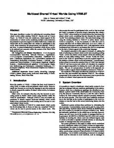
4. ATM LAN Design We describe a hypercube-based virtual topology together with switch-level hardware support for efficient multicast operations. More specifically, we focus on multicast operations between clusters of high-performance workstations with known patterns of communications in a distributed parallel computing environment. 4.1 Virtual Topology The multicast virtual topology is based on properties found in hypercubes. "An r-dimensional hypercube has N = 2r nodes and r2r-1 edges. Each node corresponds to an r-bit binary string, and
6
0110
0100
0111
0101
0010
0000
1110
1100
0011
0001
1111
1101
1010
1000
1011
1001
Figure 1 Four-dimensional 16-node hypercube two nodes are linked with an edge if and only if their binary strings differ in precisely one bit." [LEI92]. Figure 1 shows a 16-node hypercube with binary bit strings marked for each node. For the prototype model, we use the 16-node hypercube, and identify groups of nodes in the hypercube to represent our workstation clusters. We refer to the groups of nodes in the hypercube as flats, which are marked in Figure 2. We define a flat as an i-dimensional hypercube contained within an r-dimensional hypercube, where i < r. In the model depicted in Figure 2, each node in a given flat has the same bit pattern in the two high-order bits. We label each flat with these two bits. Figure 2 shows the multicast flats 00, 01, 10, and 11, which we abstractly associate with our workstation clusters. Each workstation cluster in our actual model is interconnected by one switching node that is described in Section 4.2.
7
01 0110
11 0111
0100
0101
0010
1110
1100
0011
0000
0001
1111
1101
1010
1011
1000
00
1001
10
Figure 2 16-node hypercube with flats marked
The hypercube was chosen as a basis for our virtual topology for the following reasons: • Routing decisions can be made easily by routing based on dimension. A representative example called dimension-ordered routing [MXE94], resolves dimensions from lowest to highest order. For example, a message sent on a 16-node hypercube topology (see Figure 1) from node 1010 to node 1101 would follow the route 1010 →1011→1001→1101. • The structure of a hypercube of node degree greater than or equal to two allows for more than one route from any source to any destination. This characteristic allows for adaptive routing techniques that can enhance fault tolerance [GYA93]. • Its symmetric nature and binary structure allow it to be utilized for algorithms developed for arrays and trees [LEI92].
8
4.2 Hardware Support A multistage interconnection network (MIN) that incorporates internal support for multicast is used in the network model to interconnect our workstation clusters. A MIN connects input devices to output devices through a series of stages, with each element of each stage representing a crossbar network [DYN97]. An Omega topology, with 2×2 switching elements, was chosen for our MIN as a representative from the class of topologically equivalent, hypercubic networks 8 x 8 Omega Switch 000
0
E
I
000 001
B
F
J
010 011
100 101
C
G
K
100 101
110 111
D
H
L
110 111
001 010 011
A
1
Figure 3 Multistage interconnection network with an Omega topology which includes the Butterfly, Delta, Baseline, and Flip networks. The model uses an 8×8 MIN with an Omega topology as shown in Figure 3. The topology of our Omega switch is described below. The definition was adapted directly from the definition of Omega networks found in [LEI92].
An N×N Omega switch has (N/2)log N switching elements (nodes), with each input or output edge to a node denoted by , where w ∈ {0,1}log N and 0 ≤ l ≤ (log N)-1. For each output edge out of the switching element, there is an input edge connecting to node