dedicated system keeps track of all software modules. The system ... world, plans the next action, and then acts accordingly. This paradigm focuses much on .... signals for actuators. ⢠Proxies and servers - facilitate transfer of sensor data and.
A Java-based Middleware for Control and Sensing in Mobile Robotics Thomas Hellström∗ , Thomas Johansson∗, Ola Ringdahl∗
Abstract—Many of the existing mobile-robot software packages do not include handling of sensors and actuators in a sufficiently systematic and uniform way, as described later in this section. The software framework proposed in this paper, denoted NAV2000, addresses the specific need for interchangeability of components in robotics. At the lowest level, sensors, and sometimes also actuators, often have to be replaced by similar, yet not identical, components. At a higher level, the target vehicle often changes during the work process. The presented software provides a framework that supports these replacements and allows configurations of sensors, actuators, and target machines to be specified and manipulated in an efficient manner. The system can be distributed over a network of computers if some software modules require more computing power, i.e. more hardware can be added to the system without any software changes. To accomplish sufficient monitoring of the system’s health, a dedicated system keeps track of all software modules. The system uses logfiles to enable convenient debugging and performance analysis of hardware and software modules. The software has been developed as part of, and is currently in use in, a R&Dproject for an autonomous path-tracking forest machine. Index Terms—Software engineering, Mobile-robot software, Autonomous vehicles
I. I NTRODUCTION Various tools for mobile robot software development have been proposed over the last two decades. These tools exist at many levels of abstraction, and are designed to support the development in different ways: At the highest level, the hierarchical, reactive, and hybrid robotics paradigms are represented by a number of architectures that implement the general ideas within the respective paradigm. In the hierarchical paradigm, the robot senses the world, plans the next action, and then acts accordingly. This paradigm focuses much on planning. The Nested Hierarchical Controller (NHC) [12] is a popular architecture for hierarchical systems. In the reactive paradigm, the robot reacts directly on sensor data, without any planning. The subsumption architecture [3] was one of the very first architectures put forth for building reactive systems. The hybrid paradigm is a mix of the other two and is the most common paradigm used today. Here the robot first plans how to get to the goal, then the underlying reactive system takes over and acts on this information. The system can re-plan when new sensor data arrives, or when the goal has been reached. One of the first architectures for hybrid systems was the Autonomous Robot Architecture (AuRA) [1]. At the intermediate level, there are a number of robot middleware systems, e.g. OSCAR [10], MARIE [4], CARMEN
-
-
* Department of Computing Science, Umeå University, SE-901 87 Umeå, Sweden. {thomash, thomasj, ringdahl}@cs.umu.se
WCECS 2008
[13], Orca [14], and MIRO [16]. Among the most popular middlewares today are Pyro [2] and Player [5]. All these are software frameworks to support different robotics paradigms and are sometimes called Robotic Development Environments (RDE) [11]. They provide data structures, functions, and communication protocols as a platform to build software architectures on. They often contain high-level functions, such as path-tracking and obstacle avoidance, in addition to the basic robot interface. At a lower level, networking middleware such as CORBA [8], Microsoft’s .NET Framework, and MIRPA-X [6], enables software to run on several computers with different operating systems, programming languages, and networks. They are not deigned specifically for robotics applications, but are general programming tools for distributed computing. Many of the above-mentioned robot middleware tools overlook important issues regarding target machines, actuators, and sensors. They also often lack support for distributed computing over a network. Some of the intermediate-level systems do include high-level handling of sensors and actuators, but not in a sufficiently systematic and uniform way. The work presented in this paper attempts to fill this gap, and provide a link between physical sensors/actuators (or rather their software counterparts) and the overall control program. The system proposed here, denoted NAV2000, covers the lower level and a significant part of the intermediate level. Instead of a networking middleware, Java is used for (among other things) transparent network communication. The development started in 2002 as part of a project for research in the area of autonomous path-tracking forest machines [9], [15]. This project is used in this paper to exemplify the various concepts in the NAV2000 design. It should be emphasized that NAV2000 does not aim at taking the same role as some of the robot middleware systems mentioned above. Many of these systems provide support for a wide range of different sensors, robot platforms and algorithms for obstacles avoidance and path-tracking for example. While we have implemented such algorithms, they are not part of the NAV2000 system. The proposed software infrastructure for control and sensing should be seen as support, or a framework basis, for a complete development environment. NAV2000 is programmed in Java because of its suitability for rapid testing and evaluation, and its support of an Object-Oriented system. Java has built-in multi-tasking (threading) and also supports networked systems, which makes it easier to deploy the system on several computers without using networking middleware. This also makes it possible to use several vehicles simultaneously. They may communicate with eachother and with
-
649
all sensors in the system (e.g. a vehicle can listen to sensors mounted on other vehicles). One of the main advantages to NAV2000 is the use of configuration files that nullifies the need to make any changes in the source code if conditions change. This also makes it easy to add new sensors and vehicles. II. M OTIVATION The work has been driven by an identified need for interchangeability of hardware components in the development and use of robotics systems. This need surfaces at many levels in the systems, and at many stages in the development process: At the lowest level, sensors, and sometimes also actuators, often have to be replaced by similar yet not identical components. In a complex system, this may very well mean that a sensor of one type has to be replaced by one of another type, which may be connected to another computer. This kind of replacement is often a major part of the development and research process, where different kinds of algorithms, sensors, and setups have to be evaluated and compared. Sometimes another computer is involved, if some modules require more computing power. Furthermore, interchangeability is also often needed in a running robot. For example, a satellite navigator may have to be replaced by odometry if the satellite signals are occluded, or a laser scanner used for obstacle detection may have to be replaced by a radar sensor due to weather changes. At a higher level, the target vehicle for the developed system is often changed during the work process. This is a practical and efficient approach, especially when developing systems for large autonomous vehicles [9], [15]. Furthermore, support for this level of interchangeability will become more and more important as generic robotics systems are developed for many types of tasks and platforms. Interchangeability can be implemented in robotics software in many ways, also without any special tools supporting it. However, as robotics systems become more and more complex, such tools become invaluable. III. D ESIGN
CRITERIA
The aim of the presented work is to provide a flexible and generic link between physical sensors, actuators, and similar components, and higher-level control softwares (e.g path-tracking). It has been driven primarily by three basic requirements: Interchangeability - Similar hardware components and their corresponding driver routines should have a common interface (”look and feel”) to enable interchanging them at an appropriate level, without the need for modifications of the rest of the system. In fact, the system is designed so higherlevel routines would have limited knowledge of the actual implementation. Virtual modules - Instead of rewriting a sensor, e.g to implement sensor fusion, a new module responsible only for this function is developed, then used in place of the old sensor, and also uses the old sensor for input data. In the same way we can have a virtual vehicle that extends the functionality of a real vehicle. For example a small robot could
-
-
650
mimic the behavior of a larger vehicle (e.g. slower steering response). Several such virtual sensors or vehicles could be strung together. Distributed processing - The system should be adaptable to both differing demands of computing power and different configurations during test and “production”. During in-office testing, all modules could be loaded on to a single more powerful computer, but in field trials two (or more) mobile computers may share the processing load. Vital for understanding the difference between virtual modules and interchangeability is that the latter deals with replacing one sort of software module with another, similar module - two different speed sensors for instance. A virtual speed sensor, on the other hand, is not really a piece of software directly communicating with a sensor; it can be a filter or a network proxy that serves in the sensor’s place while adding some functionality. From these requirements a set of more detailed goals can be specified to facilitate the design of the system: Modularity: A software module is the basic building block of the system. Modules exist in a type hierarchy, with subtypes being, among others, sensors, vehicles, and actuators. At the top level in the hierarchy all modules have a common interface, i.e. they can perform a common set of operations, such as close, open, and return status. This property of modules is used by the system to load, start, stop, and interrogate modules on a high level, without knowing the detailed function of the particular module. A common loader for all types, which processes an initialization file with module names and actual types, loads the modules. On a lower level, all modules of a certain subtype, such as all speed sensors, can be interchanged and still handled similarly by the sensor users. Extensibility and flexibility: New modules and module types should be easy to add to the system without any changes to the existing software. An important feature of the system is the low coupling between modules, i.e. they are effectively isolated from one another regarding internal representation of data and functions. Only the exposed external interface is shown, and if a new module of a certain type is added, it can be treated as any other module of this type. An example would be a speed sensor type, which only has the function getSpeed. This leaves it up to the implementers to design the module in any way they want, as long as the module delivers data via its getSpeed function. In a practical system there may exist several speed sensors, which take data from the machine itself or from a GPS receiver, but the rest of the system does not know and does not need to know, the actual sensor used at any given time. If a new type of speed sensor is installed, its corresponding speed sensor module can be added to the system without any changes to existing code. Which sensor to use can be configured at start-up or dynamically changed at runtime. Cohesion: The modules are designed for high cohesion, i.e. a module does just one thing, but does it well. An example would be a sensor that requires some form of filtering of its data. Instead of incorporating filter code in the sensor module (and thus in all sensor modules that require it), a special filter module is developed. The filter module would have the same
-
-
-
-
WCECS 2008
type as the sensor, and in effect would be a virtual sensor, which is used in the normal sensor’s place. The filter module then uses the actual sensor as its data source. This virtual sensor will for all intents and purposes look exactly like a “real” sensor to the users of the sensor data. In addition, the modules have to have low coupling, i.e. a low dependency on other modules. Multithreading: Every module should have its own execution thread, and thus run independently of other modules. Polling loops are discouraged; instead, an event-driven system is used with multiple independently executing threads. The threads normally sleep and only wake up if a message arrives from another module, from the network, or a user. Network Communication: Modules can be located on several host systems, and there must be a way they can communicate transparently, regardless of the actual configuration, i.e. modules should not be aware of whether they are located on the same computer as the modules they communicate with, or a different one.
-
-
IV. M ODULES NAV2000 uses Java Interfaces for different sub-trees in the architecture: The top root is a Module, under which there are a Sensor tree, a Vehicle tree, a Proxy tree, and so on. In parallel to the interface hierarchy there are also abstract base classes that supply common functionality to the subclasses. One example is BasicModule that implements the interface Module. This abstract class contains a lot of the internal workings that a module might need; loading of parameters, status reporting, and logging initialization. The class BasicSensor likewise implements Sensor and inherits BasicModule. It contains sensor-specific functionality such as data encoding and decoding functions, conversion between little/bigendianness, and support for message notification (observersubject-pattern). The classes implemented in the NAV2000 system broadly represent different types of components in a robotics system: • Sensors - represent hardware units that deliver sensor data, e.g. speed, heading, and position. • Actuators - represent hardware units that control external equipment, e.g. throttle, steering angle, and brakes. • Vehicles - several implementations of real and virtual vehicles. • Controllers - process sensor data and compute control signals for actuators. • Proxies and servers - facilitate transfer of sensor data and control commands over a network (Ethernet or WLAN). These modules hide the actual structures needed to use the network, so a module has the same look and feel whether it is used over a network or not. All modules have a few methods and data elements (attributes) in common: init: initialize the module, finish: general housekeeping at shutdown, open: activate the module, close: deactivate the module, getName: return the name of the module, getStatus: return the status (e.g. errors), setParameter: set any parameter (e.g. calibration), getParameter: return the value of a parameter. Parameters are special persistent data elements, i.e. they are
WCECS 2008
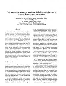
kept on permanent storage between runs. An example would be calibration parameters that, once set, are reloaded at every start of the system. A Sensor has only one more method than the Module base class, the getPose method. It returns the actual position and attitude of a sensor relative to the vehicle it is mounted on. Further down the hierarchy there are special versions of Sensors, for example the RangeArraySensor, an array of range sensors, such as sonars. This class specifies a few more methods: getRanges: return the range to each obstacle, getPoses: return the mounting pose of each range sensor, getTimeStamps: return the time of the last measurement for each range sensor. A PositionSensor contains both the mounting pose returned by the getPose method, and the position measured by the sensor, returned by getPosition. Timestamp is also incorporated into the data returned by all sensor classes, to facilitate correct time stamping of data. In general, all data, be it speed, steering angle, or gyro temperature, are timestamped, since it is important for higher-level routines and fusion systems to be able to match data taken by different sensors that are not always synchronized. Also, this timestamping is used for health checks and as a means for estimating the performance of the system, in particular the network communication. At the bottom of the class hierarchy the actual implementation classes exist, i.e. classes that can be instantiated. A class diagram for parts of the forest machine system is shown in Figure 1. V. I NTER -M ODULE DATA F LOW One of the central tasks of the system is the swift delivery of data from sensor to user, be it a control loop or a module for remote-controlling (teleoperate) the vehicle. In many systems the data-flow is based on “polling”, where interested modules must ask for sensor data, without knowing if there are any new data available. The data flow in our system is eventdriven, meaning that when a module has new data to deliver, it signals other interested modules. Since all modules are autonomous, this allows them to deliver data at their own pace. For this to function, there are two requirements: “usermodules” must be able to find the data sources, and have to be able to register interest in the data. The modules can find each other with the help of the Registry, described later in this section. To set up and remove a module’s interests in data, the two methods addObserver and deleteObserver are used. An observer, also called listener, is a special property that can be assigned to any class, and a subject is something an observer observes [7]. Observers and subjects are part of the eventdriven data flow, which is the dominant and preferred way to move data through the system. Its basic mechanism consists of subjects, for instance sensors that notify its observers whenever a new measurement value is available. The listeners, which in turn may be subjects, process this data and then notify their observers, and so on. The data finally reaches the end user, normally a control loop in the system or an external system, e.g. a Matlab program. Matlab is not easily amendable to the event-driven paradigm, so the last step in the chain is a
651
GpsPosition PositionSensor +getPosition() +getTimeStamp()
Odometry
SpeedSensor
GpsSpeed
AngleSensor
VehicleAngle
+getSteeringAngle() +getTimeStamp() Sensor
+getRanges() +getPoses() +getTimeStamps()
Radar
Sonar AttitudeSensor
Controller +setEnabled()
New set speed
LaserScanner
RangeArraySensor Vehicle
VehicleProxy
Current speed
Matlab control loop
+getPose()
+setSpeed() +setAngle() +setThrottle() +setTurnRate()
+getRoll() +getPitch() +getYaw() +getTimeStamp()
HeadingSensor
Gyro
GpsHeading
+getHeading() +getTimeStamp() Odometry
Figure 1. Class diagram for parts of the forest machine system. Only the sensor subclasses are fully described in this diagram. All “real” sensors are instances of one of the classes shown to the far right. All other classes implement general functionality inherited by their subclasses. Some of the methods that must be implemented are shown in the respective class.
standard polling of data. A subject can have any number of listeners, and an observer can observe any number of subjects. An example would be a display that presents some combined and interdependent data, for instance a map that listens to both a position sensor and a heading sensor, and plots the vehicle’s position and direction. A set of support classes is available for all modules, and the two most important ones are Loader and Registry. The Loader is the class responsible for loading, opening, closing, and finishing all modules, and can deliver a list of all loaded modules within a specified class, for instance all loaded speed sensors. The Health Monitoring system (further described in Section VIII) uses this to keep track of all modules and periodically query them for their status. Since all modules must have a getStatus-method, the Health Monitor can do this knowing only that it is dealing with a subclass to Module. The Registry keeps track of the names given to all loaded modules, so an actual module can be found by its name. This functionality is used by most modules to identify and find their subjects, i.e. the other modules it wants to observe. The Registry can also hold arbitrary data, like default network addresses for the local and remote systems, default timeouts, and what level of debugging should be used. Debugging can be customized for every module, from none to very detailed, and also on a top level, enabling a user to turn on and off all debugging from a central point.
652
Stationary computer SpeedProxy
Actuator
VehicleServer
WLAN
Module +init() +finish() +open() +close() +getName() +getStatus() +setParameter() +getParameter()
New set speed
HTUSpeedSensor
+getSpeed() +getTimeStamp()
Server
Vehicle
Current speed
SpeedServer
Proxy +getPose() +getTimeStamp()
Mobile computer GpsSpeedSensor
Figure 2. With Server-Proxy-pairs, the system can be used with two or more computers, connected via a network. The Proxy acts as a virtual module, so the user does not have to know whether a network is used or not.
VI. C OMMUNICATION The modules in the system may reside on different computers. The communication routines in NAV2000 take care of the data routing, and make the actual location of each module transparent to other modules. Every module of the type SpeedSensor, PositionSensor, etc., has a virtual companion used in place of the real sensor when it is located on another computer. This virtual sensor is of the type Proxy, so there are SpeedProxies, PositionProxies, etc. Every Proxy communicates with a Server, which is its counterpart on the other side of the network. A simple connection between a user of data, e.g. a Matlab program, and a sensor, will be extended by a ProxyServer-pair as illustrated in Figure 2. In this example, a speedmeasurement is sent from the GpsSpeedSensor (which listens to a physical sensor) to the SpeedServer. The server sends the package over a network connection, where a matching proxy receives it. Since all servers broadcast their data on the network, proxies on several different computers can pick it up. A Matlab control program asks the SpeedProxy for the current speed, determines a new set speed, and sends it to the VehicleProxy. Here the data is again sent over the network, received by the VehicleServer, which in turn passes it on to the Vehicle object. This object is responsible for adjusting the speed on the physical vehicle. Since a SpeedProxy also inherits all methods from the SpeedSensor class, it can be regarded as a sensor in its own right, although it is only a virtual sensor. This is one of the fundamental characteristics of this proposed architecture: modules that are not sensors can act as if they were. The concept of virtual sensors makes it possible to locate sensors and users of data on different computers without the user of the data ever having to know this. This places special demands on the Server-Proxy-pair, since it has to deliver that data as swiftly as possible, and also implement the routines for getting and setting parameters over the network. Reorganizing a system from a single-computer operation to several computers involves loading proxies instead of sensors on the ”user-computer”, and loading servers instead of users on the ”sensor-computer”. No changes have to be made to either user or sensor code; all is accomplished by modifying configuration files as described in Section VII.
WCECS 2008
Communication between separate computers is done by Ethernet network, either directly through a cable or via a Wireless Local Area Network (WLAN). The WLAN is used for controlling the vehicle, but since the communication handling is transparent to the system, debug and in-office tests can be done by either a cable or direct communication within the computer. The network communication uses datagrams (by the Internet UDP protocol), i.e. small packets of data transmitted with no control over their arrival, and therefore no acknowledgment of received packets is obtained. The alternative would be TCP streams, which guarantee the order, integrity, and completeness of the data. The reason for this choice is threefold: Datagrams can be broadcast to more than one receiver; so several computers can listen on data from the sensors. Datagrams delineate the data on the network. The data is conveniently seen as small units, as opposed to a data stream, where the software would have to find the beginning and end of each data packet. With datagrams, lost packets are quickly replaced by new data. A streaming model would resend lost packets, but would also impose a variable delay, and with high data rates there would be new data available by the time the original one arrives. TCP also uses bigger packets. Small packets have a greater chance of getting through the network, and the loss of a few packets is normally tolerable. Up-to-date data is often more important than a complete data stream. For protection against a complete loss of control should the network fail, there are several timeouts built into the system.
-
VII. C ONFIGURATION The software drivers for sensors, actuators, and target vehicles have parameters describing their function. For a sensor, this may include sampling rate, amplification level, network address, and pose. Furthermore, the integration of a target vehicle, sensors, and actuators into a complete system has to be handled in a flexible way. To facilitate this, every module has an associated initialization file with properties that control the module’s behavior. Most of these properties are set once and for all, while others are changed either by the user or by the module itself. The module can also save the changes so they take effect upon the next time the system is run. One example would be an experiment to find the most appropriate gain for a specific sensor; when a suitable value is found, the sensor can store it in its initialization file. The next time the sensor is run, it automatically uses the saved value. The files are stored in separate file folders, one per configuration. Together with the initialization files there is a configuration file that describes the system (choice of target vehicles, sensors, actuators, etc.) and which modules to load. Usually this startup configuration file is stored together with the initialization files for the modules to load in that particular configuration. To start the system, a small boot-loader program reads the configuration from a file, and proceeds to load the appropriate modules. The user can select the configuration to load from a menu, or its name could be hard-coded into the boot loader. In this way, different versions (choices of sensors, filters, etc.) can be easily available during development.
WCECS 2008
The forest machine system contains more than 100 different modules, with initialization files. To facilitate changes and provide an overview a graphical configuration manager has been developed. The configuration manager gives the user an overview of how every module is connected to other modules. It is possible to reroute connections, add new modules, duplicate existing ones, or remove them. The configuration manager can also be used to modify individual properties for the module such as the mounting pose of the sensor, update frequency, and the level of debugging. VIII. H EALTH M ONITORING
AND OTHER SUPPORT
SYSTEMS
The system has a powerful set of support systems. Among the more important are the Health Monitor and the Logging System. The latter uses a class hierarchy for the output of log data, with Logger as the base class. The most common output channel is a log file (accomplished by the FileLogger), but by substituting other classes the logging can be rerouted to a database, or a memory buffer if time tests demand a low time loss impact from the logging. Logging can be enabled and disabled at a global level and also at the module level, by using instructions in the initialization files. A log record has a number of columns that can be turned on or off. They contain actual time, time elapsed since the start of the log, class, method, and line number of the logging instruction in the code. The columns can also contain a comment supplied in the argument to the log command, and a list of the enabling flags in effect. These flags make it possible to turn on or off a special type of logging event, e.g. UPDATE for data broadcasting, NETWORK for network events, EXCEPTION for error reporting, and LOWLEVEL for detailed logging of, for instance, character-by-character processing in a communications module. The actual logging command takes such a flag as an argument and only contributes to the output if the corresponding flag is enabled. Reliable procedures for checking the status of both sensors and actuators become increasingly important as the complexity of robot systems grows. The NAV2000 system will in itself increase the need for such procedures, since it introduces new levels of abstraction between the hardware and the user program, and also since it offers flexible and configurable setups. The use of timeouts, ”watch-dogs”, and ”heart-beats” addresses the same need, but not sufficiently for a complex system with numerous asynchronous communication channels and interconnected subsystems. To accomplish sufficient health monitoring, a dedicated system keeps track of all modules loaded onto the local computer, and also communicates with health monitors in all other computers running the system. The overall health of every module as well as a more detailed description of possible problems is available, as seen in Figure 3. Error types fall into several groups, of which hardware timeouts (lost communication with sensors), configuration errors, hardware errors, and network problems are the most prominent. From the data collected by this system it is also possible to get statistics on the performance of the system, mainly the time delay from a measurement until the
653
arrives the serial number is increased by one. It is fairly uncommon that a package is lost over the network, over 97% of the packages arrive safely. To lose two consecutive packages or more is even less likely; 0.2% of all packages in this test. The proposed software structure has proved to be a consistent and powerful tool for the research work. It will be further extended and improved, and will serve as a general basis for our future work with autonomous vehicles and robots. Figure 3. The Health Monitor system keeps track of all loaded modules in the system, and warns if any error occurs. A filled icon in front of a module’s name means that it functions properly. If the icon is striped, the module has some problem. Details about the cause of the problem are displayed when clicking on the module’s name.
ACKNOWLEDGMENT We would like to thank Jürgen Börstler for his valuable inputs on refining and improving the contents of this paper. R EFERENCES
70
Number of occurences [%]
60
50
40
30
20
10
0 0
5
10
15
20
25
Delay [ms]
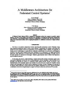
Figure 4. The average time delay over a network measured by sending a package over the network and back again. For about 70% of the tested packages, the delay is less than 2 milliseconds. The maximum delay of the 135 packages sent over the network in this test was 24 milliseconds.
data arrives at its final destination. The Health Monitor is essential for both development and usage of a complex robotics system. During development, important information regarding missing sensors or incorrect configurations can be retrieved. During the usage of a ready-build robot, the Health Monitor can be used to detect malfunctioning sensors, actuators, and other equipment. IX. C ONCLUSIONS The NAV2000 system is in daily use in the development and research work in the forest machine project that has been used as an example in this paper. In this project, three different target machines are interchangeably used and a number of varying configurations of sensors and actuators are applied for testing and system integration. Currently the system consists of over 300 different classes. Figure 4 shows the average time delay over a network. Because the two computers involved do not have the same time (even if we try to synchronize them), the time it takes to send a package over the network and back again was measured. Half this time is the delay over the network. For about 70% of the tested packages, the delay was less than 2 milliseconds and it never exceeded 24 milliseconds in our tests. Another important performance issue is the number of packages lost over the network. This is measured by analyzing packages containing a serial number. Each time new data
654
[1] R.C Arkin. Path planning for a vision-based autonomous robot. In Proceedings of the SPIE Conference on Mobile Robotics, 1986. [2] D. Blank, L. Meeden, and D. Kumar. Python robotics: An environment for exploring robotics beyond legos. In ACM Special Interest Group: Computer Science Education Conference, 2002. [3] R.A. Brooks. A robust layered control system for a mobile robot. IEEE Journal of Robotics and Automation, 1(1):1–10, 1986. [4] Côté C., Létourneau D., Michaud F., Valin J.-M., Brosseau Y., Raïevsky C., Lemay M., and V. Tran. Code reusability tools for programming mobile robots. In Proceedings IEEE/RSJ International Conference on Intelligent Robots and Systems, pages 1820–1825, 2004. [5] T.H.J. Collett and B.A. MacDonald. Augmented reality visualisation for player. In Proceedings of the the IEEE International Conference on Robotics and Automation (ICRA 2006), pages 3954–3959, May 2006. [6] B. Finkemeyer, M. Borchard, and F. Wahl. A robot control architecture based on an object server. In IASTED International Conference Robotics and Manufacturing, pages 36–40, 2001. [7] E. Gamma, R. Helm, R. Johnson, and J. Vlissides. Design Patterns: Elements of Reusable Object-Oriented Software. Addison-Wesley, 1994. ISBN 0-201-63361-2. [8] Object Management Group. http://www.omg.org/, 01 2007. [9] Thomas Hellström, Thomas Johansson, and Ola Ringdahl. Development of an Autonomous Forest Machine for Path Tracking, volume 25 of Springer Tracts in Advanced Robotics, pages 603 – 614. Springer, field and service robotics: results of the 5th international conference edition, 2006. [10] C Kapoor. A Reusable Operational Software Architecture for Advanced Robotics. PhD thesis, University of Texas at Austin, 1996. [11] James Kramer and Matthias Scheutz. Robotic development environments for autonomous mobile robots: A survey. Autonomous Robots, 22(2):101–132, 2007. [12] A. Meystel. Knowledge based nested hierarchical control, ed. g. saridis, jai press, greenwich, ct, 1990, pp. 63-152. In G. Saridis, editor, Advances in Automation and Robotics, volume 2, pages 63–152. JAI Press, Greenwich, CT, 1990. [13] Michael Montemerlo, Nicholas Roy, and Sebastian Thrun. Perspectives on standardization in mobile robot programming: The carnegie mellon navigation (carmen) toolkit. In Proceedings of the IEEE/RSJ International Conference on Intelligent Robots and Systems (IROS 2003), volume 3, pages 2436–2441, Las Vegas, NV, October 2003. [14] Anders Orebäck. A Component Framework for Autonomous Mobile Robots. PhD thesis, Center of Autonomous Systems, Royal Institute of Technology, Sweden, 2004. [15] Ola Ringdahl. Techniques and Algorithms for Autonomous Vehicles in Forest Environment. Licentiate thesis, Department of Computing Science, Umeå University, 2007. [16] Hans Utz, Stefan Sablatnög, Stefan Enderle, and G. K. Kraetzschmar. Miro – middleware for mobile robot applications. IEEE Transactions on Robotics and Automation, Special Issue on Object-Oriented Distributed Control Architectures, 18(4):493–497, August 2002.
WCECS 2008