Hindawi Publishing Corporation Journal of Applied Mathematics Volume 2014, Article ID 861782, 12 pages http://dx.doi.org/10.1155/2014/861782
Research Article A Joint Encryption and Reversible Data Hiding Scheme Based on Integer-DWT and Arnold Map Permutation Shun Zhang, Tiegang Gao, and Guorui Sheng College of Software, Nankai University, Wei Jin Road No. 94, Nankai District, Tianjin 300071, China Correspondence should be addressed to Shun Zhang;
[email protected] Received 6 January 2014; Revised 26 March 2014; Accepted 26 March 2014; Published 9 April 2014 Academic Editor: Feng Gao Copyright © 2014 Shun Zhang et al. This is an open access article distributed under the Creative Commons Attribution License, which permits unrestricted use, distribution, and reproduction in any medium, provided the original work is properly cited. A joint encryption and reversible data hiding (joint encryption-RDH) scheme is proposed in this paper. The cover image is transformed to the frequency domain with integer discrete wavelet transform (integer DWT) for the encryption and data hiding. Additional data is hidden into the permuted middle (LH, HL) and high (HH) frequency subbands of integer DWT coefficients with a histogram modification based method. A combination of permutations both in the frequency domain and in the spatial domain is imposed for the encryption. In the receiving end, the encrypted image with hidden data can be decrypted to the image with hidden data, which is similar to the original image without hidden data, by only using the encryption key; if someone has both the data hiding key and the encryption key, he can both extract the hidden data and reversibly recover the original image. Experimental results demonstrate that, compared with existing joint encryption-RDH schemes, the proposed scheme has gained larger embedding capacity, and the distribution of the encrypted image with data hidden has a random like behavior. It can also achieve the lossless restoration of the cover image.
1. Introduction Compared with traditional watermarking and data hiding schemes, reversible data hiding schemes can be applied in a larger field of secure communication and watermarking due to its reversibility. Many reversible data hiding schemes have been proposed in recent years, which can be classified into three main catalogues: the first one is compression based scheme [1], the second one is difference expansion based scheme [2–5], and the third one is histogram modification based scheme [6–10]. Reversible data hiding based on compression makes use of the redundancy of cover images, so the characters of the cover images limit the capacity and quality of data hiding. Difference expansion based scheme was firstly proposed by Tian [5], which hid one-bit data by extending the difference between two neighbor pixels. Alattar [2–4] improved the hiding capacity by extending 𝑛 − 1 pairs of neighbor pixels’ differences to hide 𝑛 − 1 bitsdata. However, the quality of the cover image drops quickly, while the hiding capacity increases. Schemes based on histogram modification cause less distortion to the cover image. However, the peak points of the histogram limit the hiding capacity [11]. There
are two measures to increase the hiding capacity in histogram modification based data hiding schemes: raising the peak points’ height or increasing the number of peak points. Many schemes based on the two ways have been proposed. Lin et al. [6] proposed a multilevel embedding strategy to increase the number of peak points. Some schemes increased the height of the peak points through generating the histogram of the difference image. For example, Tsai et al. [8] constructed the difference image by a prediction model that makes full use of the similarity between neighbor pixels. Kim et al. [12] sampled the original image to construct the difference images. A predicted image based on the sampled images was constructed. Then the histograms of difference images between the predicted image and these sampled images were generated for data hiding. As is well known, encryption is an old and efficient way in secure communication. If combined with encryption, reversible data hiding will achieve greater security. Besides, there are also scenarios that data hiding needs to be done in the encrypted domain or combined with the encryption, especially in the age of big data and cloud computing. A content owner does not trust the processing service provider, and
2 the ability to manipulate the encrypted data while keeping the plain content unrevealed is desired [13]. Suppose that there are sensitive images uploaded to the cloud storage in the encrypted form and some additional data needs to be hidden into these images to mark their ownership. However, the data hiding process has to be done in the encrypted domain because the data administrator does not have the right and the key to decrypt the image. In the past few years, some schemes that combine encryption and data hiding have been proposed [13–18]. From the data hider’s point of view, data can be hidden into the spatial domain, the encrypted domain [13, 14, 16–18], or both of the two domains [15]. Although high image quality after data hiding has been achieved in [15], the scheme is not reversible. Reversible data hiding schemes in encrypted images are proposed in [13, 14]. In [14], an improved measurement of smoothness is proposed to make full use of all the pixels in the image, and a side match scheme is proposed to further decrease the error rate of extracted bits, both of which have improved the embedding capacity of the basic data hiding scheme in the encrypted image proposed in [13]. In [16], a reversible data hiding scheme in encrypted images by reserving room before encryption is proposed. The self-embedding of LSB planes guarantees the reversibility of LSB substitution embedding. However, the embedding capacity is limited by the embedding capacity of the reversible data hiding scheme in the selected area. In [17], some pixels are selected and estimated before encryption, and additional data is embedded into the estimated errors with a histogram modification method. In the receiving end, one can either decrypt the image with hidden data first or extract the hidden data first. Scheme proposed in [18] separates the data extraction and the recovery of original image. The image is encrypted with the encryption key. Then the encrypted image is passed to the data hider, and additional data is embedded into the encrypted image with the data hiding key. In the receiving end, the hidden data can be extracted with only the data hiding key; and only similar (not reversible) image can be recovered with the encryption key; both the hidden data can be extracted and original image can be reversibly recovered with both keys. Different from all the joint encryption and data hiding schemes mentioned above, a joint encryption and reversible data hiding scheme based on integer DWT and Arnold map permutation is proposed. Not in the spatial domain, the data hiding is imposed in the integer DWT domain, which is more secure compared with those schemes in the spatial domain. The cover image is firstly transformed to the frequency domain with discrete integer wavelet transform (integer DWT). Then coefficients of the four subbands are permutated with Arnold map transform, respectively, for the first time. After that, additional data is embedded into the permuted middle (LH, HL) and high (HH) frequency subbands through a histogram modification based method. Finally, inverse integer DWT is imposed to get the primary encrypted image with hidden data. Another Arnold permutation based on sampling, which is related to the permutation in the frequency domain, is imposed on the primary encrypted image with hidden data in the spatial domain. In the receiving
Journal of Applied Mathematics end, one can decrypt the image to get the image with hidden data, which is similar to the original image without hidden data, by only using the encryption key that includes permutation times of the twice permutations. If someone has both the encryption key and the data hiding key, he can both extract the hidden data and reversibly recover the original image. Note that the processing procedures in the sending end and in the receiving end described here are asymmetric, which can achieve many applications, such as scenarios mentioned above.
2. Preliminaries 2.1. Integer DWT. To achieve the reversible data hiding, reversible lifting integer DWT is applied. Integer DWT is implemented with the addition and subtraction of integers. Suppose that 𝐼(𝑥, 𝑦), 1 ≤ 𝑥 ≤ 𝑀, 1 ≤ 𝑦 ≤ 𝑁, is the pixel of the image size of 𝑀 × 𝑁; then 2D integer DWT is conducted as follows. (A) Row Transformation (1) Let 𝑓1 = 𝐼(2 ∗ 𝑖 − 1, :) and 𝑓2 = 𝐼(2 ∗ 𝑖, :), 𝑖 = 1, 2, . . . , 𝑀/2, which are odd rows and even rows of 𝐼, respectively. (2) Acquire the high frequency coefficients by calculating the difference of the two: ℎ 𝑟(𝑖, :) = 𝑓1(𝑖, :) − 𝑓2(𝑖, :). (3) Acquire the low frequency coefficients by calculating the average of the two: 𝑙 𝑟(𝑖, :) = 𝑓2(𝑖, :)+floor(ℎ(𝑖, :)). (4) Then coefficients after 1D transformation are 𝐶 row = [𝑙 𝑟; ℎ 𝑟]. (B) Column Transformation (1) Let 𝑓1 = 𝐼(:, 2 ∗ 𝑖 − 1) and 𝑓2 = 𝐶 row(:, 2 ∗ 𝑖), 𝑖 = 1, 2, . . . , 𝑁/2, which are odd columns and even columns of 𝐶 row, respectively. (2) Acquire the high frequency coefficients by calculating the difference of the two: ℎ 𝑐(:, 𝑖) = 𝑓1(:, 𝑖) − 𝑓2(:, 𝑖). (3) Acquire the low frequency coefficients by calculating the average of the two: 𝑙 𝑐(:, 𝑖) = 𝑓2(:, 𝑖)+floor(ℎ(:, 𝑖)). (4) Finally, the coefficients of 2D integer DWT are 𝐶 = [𝑙 𝑐 ℎ 𝑐]. 2.2. Reversible Data Hiding and Data Extraction Based on Histogram Expansion. Ni et al. [19] firstly proposed reversible data hiding based on histogram modification. It generates the histogram of an image; then a pair of peak point and zero point is found out in the histogram, and the histogram between peak point and zero point is shifted to the zero point side to produce the gap for data hiding. Very little distortion will be caused by such schemes, and Ni et al. [19] have pointed out that the peak signal-to-noise ratio (PSNR) between the original image and the image with hidden data is above 48. As mentioned in the beginning part of the paper, the drawback is the rare capacity of data hiding. A novel histogram modification based reversible data hiding scheme in integer DWT domain, which increases the capacity of data hiding greatly,
Journal of Applied Mathematics
3 7000 6000 LH
LL
5000 4000 3000 2000
HL
HH 1000 0 −100
−50
(a) Subbands of DWT
7000
3500
6000
3000
5000
2500
4000
2000
3000
1500
2000
1000
1000
500
0 −100
−50
0
0
50
100
(b) Histogram of HH of original Lena
50
100
(c) Histogram of HH of histogram shifted Lena
0 −150
−100
−50
0
50
100
150
(d) Histogram of HH of data embedded Lena
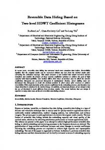
Figure 1: An example of histogram modification (HH subband of integer DWT of Lena).
is described here. Histograms of middle and high frequency subbands of integer DWT of images are Laplacian like distribution. Thus, they are suitable for histogram modification based data hiding method. Histograms are shifted to generate the gap for data hiding. A demo of histogram modification based data hiding method, which embeds data into the HH subbands of Lena image, is presented in Figure 1.
2.2.1. Reversible Data Embedding. The generated histogram of subband HH is depicted in Figure 1(b). Then the histogram is shifted to both sides by an embedding strength 𝑇 (Figure 1(c)). At last, data is embedded by expanding histogram between 𝑇 and −𝑇, and the histogram after embedding is as Figure 1(d). The histograms of LH, HL, and HH subbands are generated and data is embedded into the coefficients by histogram modification. For every coefficient 𝐶 of LH, HL, and HH subbands, given an embedding strength parameter 𝑞,
(1) if 𝐶 ≥ 𝑞, then 𝐶 is shifted to 𝐶 + 𝑞; (2) else if 𝐶 ≤ −𝑞, then 𝐶 is shifted to 𝐶 − 𝑞 + 1; (3) else 𝐶 ← 2 × 𝐶 + 𝐵, and 𝐵 is the data to be embedded. 2.2.2. Data Extraction and Reversible Recovery of Matrix before Embedding. Generate the histograms of middle and high frequency subbands and shift these histograms to extract the hidden data, and the original coefficient matrices are reversibly recovered through the following steps. For every coefficient 𝐶 of LH, HL, and HH subbands, given an embedding strength parameter 𝑞, (1) if 𝐶 ≥ 2 × 𝑞, then 𝐶 is shifted to 𝐶 − 𝑞; (2) else if 𝐶 ≤ −2 × 𝑞 + 1, then 𝐶 is shifted to 𝐶 + 𝑞 − 1; (3) else 𝐶 ← floor(𝐶/2), and data is extracted: 𝐵 = mod (𝐶, 2).
4
Journal of Applied Mathematics
Now, every coefficient 𝐶 of subbands LH, HL, and HH is reversibly recovered and the extracted 𝐵 is the data embedded before.
(3) Impose invers integer DWT on the coefficients after permutation to get the encrypted matrix 𝑀 . (B) Sample Permutation in the Spatial Domain
2.3. Arnold Permutation [20]. Russian mathematician Vladimir I. Arnold discovered Arnold’s cat map using an image of cat. An image, not necessarily a cat, of course, can be transformed to a random noise like image by rearranging the position of original pixels. However, if iterated for moderate times (denoted by permutation periods as presented in Table 1), the original image will reappear. The permutation periods differ as the sizes of images differ. The permutation periods of images with different sizes of the traditional Arnold permutation are presented in Table 1. Let 𝐼(𝑥, 𝑦) be the pixel of an image matrix with size 𝑁×𝑁; then [ 𝑦𝑥 ] represents the position of the pixel. The Arnold 𝑥+𝑦 transform Γ can be explained as Γ [ 𝑦𝑥 ] → [ 𝑥+2𝑦 ]mod 𝑛, where mod is the modulo-operation. To better explain the theory, the transform can be decomposed into three elemental steps: in the 𝑥-direction: [ 𝑦𝑥 ] → 𝑦 𝑥 [ 𝑥+𝑦 𝑦 ], in the 𝑦-direction: [ 𝑦 ] → [ 𝑥+𝑦 ], and in the modulooperation: [ 𝑦𝑥 ] → [ 𝑦𝑥 ] mod 𝑛. 2.4. Permutation in the Frequency Domain and Sample Permutation in the Spatial Domain. Through permutation in the frequency domain, nice encryption results will be achieved. A novel encryption scheme based on the cooperation of permutation in the frequency domain and sample permutation in the spatial domain is proposed to accommodate the joint encryption-RDH scheme in this paper. It is found out through experiments that the proposed permutation in the integer DWT domain can achieve the same results as the proposed sample permutation scheme in the spatial domain. Such features are applied in the design of joint encryptionRDH scheme. Suppose that there is an image matrix 𝑀 with size 𝑁 × 𝑁, and the permutation in the integer DWT domain and sample permutation in the spatial domain are described, respectively, in the followings. (A) Permutation in the Integer DWT Domain (1) Decompose the original image matrix 𝑀 with integer DWT to obtain the four subbands (1 low frequency subband LL, 2 middle frequency subbands LH and HL, and 1 high frequency subband HH) as depicted in Figure 1(a). (2) Permute the four subbands after integer DWT with Arnold map permutation that is presented in Section 2.1, and the different permutation times are 𝑃1 𝑇, 𝑃2 𝑇, 𝑃3 𝑇, and 𝑃4 𝑇, respectively: LL = Arnold (LL, 𝑃1 𝑇) , LH = Arnold (LH, 𝑃2 𝑇) , HL = Arnold (HL, 𝑃3 𝑇) , HH = Arnold (HH, 𝑃4 𝑇) .
(1)
(1) Sample matrix 𝑀 into four submatrices: Sam1 = 𝑀 (1 : 2 : 𝑁 − 1, 1 : 2 : 𝑁 − 1) , Sam2 = 𝑀 (2 : 2 : 𝑁, 1 : 2 : 𝑁 − 1) , Sam3 = 𝑀 (1 : 2 : 𝑁 − 1, 2 : 2 : 𝑁) ,
(2)
Sam4 = 𝑀 (2 : 2 : 𝑁 − 1, 2 : 2 : 𝑁) . (2) Permute the four sampled submatrices with Arnold map with different permutation times 𝑆1 𝑇, 𝑆2 𝑇, 𝑆3 𝑇, and 𝑆4 𝑇: Sam1 = Arnold (Sam1, 𝑆1 𝑇) , Sam2 = Arnold (Sam2, 𝑆2 𝑇) , Sam3 = Arnold (Sam3, 𝑆3 𝑇) ,
(3)
Sam4 = Arnold (Sam4, 𝑆4 𝑇) . (3) Compose the permuted sampled submatrix to get the encrypted matrix 𝑀 𝑀 (1 : 2 : 𝑁 − 1, 1 : 2 : 𝑁 − 1) = Sam1 , 𝑀 (2 : 2 : 𝑁, 1 : 2 : 𝑁 − 1) = Sam2 , 𝑀 (1 : 2 : 𝑁 − 1, 2 : 2 : 𝑁) = Sam3 ,
(4)
𝑀 (2 : 2 : 𝑁 − 1, 2 : 2 : 𝑁) = Sam4 . If the permutation times are equal to the corresponding permutation times in the two permutation schemes, which mean that 𝑃1 𝑇 = 𝑆1 𝑇, 𝑃2 𝑇 = 𝑆2 𝑇, 𝑃3 𝑇 = 𝑆3 𝑇, and 𝑃4 𝑇 = 𝑆4 𝑇, the encryption results are equivalent.
3. Proposed Scheme Different from existing joint encryption-RDH schemes [13– 18], which are based on the spatial domain, the proposed scheme is based on the integer DWT domain. The detailed joint encryption-RDH scheme is presented in this section. The scheme is composed of two parts. One part is data hiding and image encryption, as presented in Figure 2; the other part is data extraction and original image recovery, which is presented in Figure 3. Note that the two parts are not symmetric. The encryption is achieved with permutation before data hiding and after data hiding in Figure 2, while the data extraction is after decryption in Figure 3. The asymmetric design can be applied in such a scenario. When someone only has the encryption key, he can decrypt the image and get the decrypted image with hidden information, which is very similar to the original image. The decrypted image can be utilized
Journal of Applied Mathematics
5 Table 1: Arnold permutation periods of images with different sizes.
Image size Period
512 × 512 384
256 × 256 192
128 × 128 96
64 × 64 48
32 × 32 24
16 × 16 12
8×8 6
4×4 3
PT Permutation on low frequency subband (LL) Original image
Integer DWT decomposing
Inverse integer DWT
Permutation on 2 middle (LH, HL) and 1 high frequency (HH) subbands PT
Information hiding in high frequency subbands
Sample permutation ST
Overhead information Encrypted image with information hidden
Information strength
Figure 2: Data hiding and image encryption.
Overhead information Overflow and underflow Received image revise
Sample permutation ST
Integer DWT decomposing
Decrypted similar image PT with hidden data
Information Information Inverse integer extraction DWT Original image Strength
Figure 3: Data extraction and image recovery.
in a variety of applications. However, he cannot get rid of the hidden data, which may work as the watermark for the copyright or authentication. In the sending end, the data hiding and image encryption process are achieved alternately. Original image 𝐼 is firstly decomposed with the integer DWT proposed in Section 2.1. Then, the Arnold permutation is imposed on the four subbands for the first time encryption. Data is embedded into the permuted middle and high frequency subbands with a reversible data hiding scheme based on histogram modification. After that inverse integer DWT is imposed to acquire the primary permuted image with hidden data 𝐼 . Finally, a sample-permutation scheme is imposed on 𝐼 to get the final encrypted image with hidden data 𝐼 . Because the reversible data hiding is based on histogram modification, overflow/ underflow is hard to avoid. Therefore, a location map for recording the positions and values of the underflow and overflow pixels in the spatial domain is constructed. The location map is compressed and encrypted as the key for data extraction. The flow chart is presented in Figure 2. In the receiving end, there are two cases. One is simple decryption, and the other one is data extraction and original image recovery. In the former case, the image with hidden data that is similar to the original image 𝐼 is decrypted. In the latter case, the hidden data is extracted and the original image 𝐼 is reversibly recovered. The received encrypted image with hidden data 𝐼 is firstly revised according to the location map. Then it is decrypted into the image with hidden data. Note that, the encryption based on the two permutations in the sending end can be decrypted by one permutation based on the sample-permutation method. The permutation based on sample permutation in the spatial domain can achieve the
same results as the permutation in the integer DWT domain as presented in Section 2.4. Besides, the data hiding scheme based on histogram modification in the integer DWT domain can be implemented either before or after the permutation in the integer DWT domain. Both of the features guarantee the asymmetric decryption and data extraction. The total permutation times are calculated according to the Arnold permutation periods of image with different sizes (Table 1), the permutation time 𝑃 𝑇 in the integer DWT domain permutation, and the permutation time 𝑆 𝑇 of the sample permutation in the spatial domain. Through the delicate design of the two permutations, decryption can be done without integer DWT and inverse integer DWT. Although additional data is hidden in the permutated integer DWT domain, the proposed histogram modification based data hiding scheme in the integer DWT domain guarantees the integrity of the hidden data and the reversibility of the original cover image. The flow chart is presented in Figure 3.
3.1. Data Hiding and Image Encryption (1) Decompose the original image 𝐼 (with size 𝑁 × 𝑁) with integer DWT (proposed in Section 2.1) to obtain the four subbands (one low frequency subband LL, two middle frequency subbands LH and HL, and one high frequency subband HH) as depicted in Figure 1(a). (2) Permute the four subbands (LL, LH, HL, and HH) with Arnold map permutation (proposed in
6
Journal of Applied Mathematics Section 2.3) synchronously. Note that, the permutation times are the same, denoted by 𝑃 𝑇: LL = Arnold (LL, 𝑃 𝑇) , HL = Arnold (HL, 𝑃 𝑇) ,
3.2. Data Extraction and Original Image Recovery
LH = Arnold (LH, 𝑃 𝑇) ,
(1) Revise the received image matrix according to location map to get image 𝐼 .
HH = Arnold (HH, 𝑃 𝑇) . (5)
(2) Sample image 𝐼 with size 𝑁 × 𝑁 into four submatrices:
(3) Embed the preprocessed data into the middle and high frequency subbands (LH, HL, and HH) with histogram modification based method (proposed in Section 2.2.1). (4) Impose invers integer DWT on the coefficients after permutation and data hiding to get the primary permuted image with hidden data, denoted by 𝐼 . (5) Sample 𝐼 to four subimages:
(6)
Sam3 = 𝐼 (1 : 2 : 𝑁 − 1, 2 : 2 : 𝑁) ,
Sam2 𝑟 = 𝐼 (2 : 2 : 𝑁, 1 : 2 : 𝑁 − 1) , Sam3 𝑟 = 𝐼 (1 : 2 : 𝑁 − 1, 2 : 2 : 𝑁) ,
Sam4 = 𝐼 (2 : 2 : 𝑁 − 1, 2 : 2 : 𝑁) .
Sam4 𝑟 = 𝐼 (2 : 2 : 𝑁 − 1, 2 : 2 : 𝑁) .
Sam1 𝑟 = Arnold (Sam1 𝑟, 𝑆1 𝑇 ) , Sam2 𝑟 = Arnold (Sam2, 𝑆2 𝑇 ) , Sam3 𝑟 = Arnold (Sam 𝑟, 𝑆3 𝑇 ) ,
(6) Permute the four sampled submatrices with Arnold map with different permutation times 𝑆1 𝑇, 𝑆2 𝑇, 𝑆3 𝑇, and 𝑆4 𝑇: Sam1 = Arnold (Sam1, 𝑆1 𝑇) , Sam2 = Arnold (Sam2, 𝑆2 𝑇) ,
(7)
Sam3 = Arnold (Sam3, 𝑆3 𝑇) ,
(10)
Sam4 𝑟 = Arnold (Sam4 𝑟, 𝑆4 𝑇 ) , where 𝑆1 𝑇 = 𝑇−𝑃 𝑇−𝑆1 𝑇, 𝑆2 𝑇 = 𝑇−𝑃 𝑇−𝑆2 𝑇, 𝑆3 𝑇 = 𝑇 − 𝑃 𝑇 − 𝑆3 𝑇, and 𝑆4 𝑇 = 𝑇 − 𝑃 𝑇 − 𝑆4 𝑇. 𝑇 is the permutation period of the sample images, and for the sample images with size 256 × 256, 𝑇 = 192, just as presented in Table 1. (4) Compose the permuted sampled submatrix to get the similar image with hidden data 𝑀 𝑠:
Sam4 = Arnold (Sam4, 𝑆4 𝑇) . (7) Compose the permuted sampled submatrix to get the postprocessed matrix 𝐼 :
𝑀 𝑠 (1 : 2 : 𝑁 − 1, 1 : 2 : 𝑁 − 1) = Sam1 𝑟 , 𝑀 𝑠 (2 : 2 : 𝑁, 1 : 2 : 𝑁 − 1) = Sam2 𝑟 ,
𝐼 (1 : 2 : 𝑁 − 1, 1 : 2 : 𝑁 − 1) = Sam1 ,
𝑀 𝑠 (1 : 2 : 𝑁 − 1, 2 : 2 : 𝑁) = Sam3 𝑟 ,
𝐼 (2 : 2 : 𝑁, 1 : 2 : 𝑁 − 1) = Sam2 ,
𝑀 𝑠 (2 : 2 : 𝑁 − 1, 2 : 2 : 𝑁) = Sam4 𝑟 .
𝐼 (1 : 2 : 𝑁 − 1, 2 : 2 : 𝑁) = Sam3 ,
(9)
(3) Permute the four sampled submatrices with Arnold map with different permutation times 𝑆1 𝑇 , 𝑆2 𝑇 , 𝑆3 𝑇 , and 𝑆4 𝑇 , respectively:
Sam1 = 𝐼 (1 : 2 : 𝑁 − 1, 1 : 2 : 𝑁 − 1) , Sam2 = 𝐼 (2 : 2 : 𝑁, 1 : 2 : 𝑁 − 1) ,
Sam1 𝑟 = 𝐼 (1 : 2 : 𝑁 − 1, 1 : 2 : 𝑁 − 1) ,
(11)
(8)
𝐼 (2 : 2 : 𝑁 − 1, 2 : 2 : 𝑁) = Sam4 . (8) Construct the location map 𝐿 of overflow and under flow pixels according to 𝐼 , and for those few overflow/underflow pixels, change their values with random integer value in the range of (0,255). These permutation times are encoded and encrypted as the encryption key. The location map and embedding strength parameters are compressed and encrypted as the data hiding key.
Until now, the decryption process has been completed, and the similar image with hidden data is 𝑀 𝑠. The hidden data can be extracted and the original image 𝐼 can be reversibly recovered through the following steps. (5) Impose integer DWT on image 𝑀 𝑠 to get the four subbands LL, LH, HL, and HH. (6) Generate the histograms of the middle (LH, HL) and high (HH) frequency subbands and shift these histograms to extract the hidden data and reversibly recover the original subbands. The detailed steps are depicted in Section 2.2.2.
Journal of Applied Mathematics
(a)
7
(b)
(c)
(d)
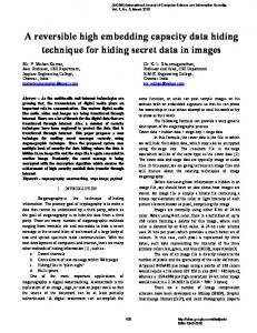
Figure 4: Images before and after disposing.
(7) Impose inverse integer DWT with the coefficients of the subbands after histogram shifting to recover the original image.
4. Experimental Results and Analysis To testify the efficiency and validity of the proposed scheme, images (with size 512 × 512) from Miscellaneous gray level images [21] and USC-SIPI image database [22] are selected for the experiments. Random binary bits are embedded into these images as the hidden data. All of these experiments are performed on the MATLAB 2012a platform running on a personal computer with CPU of AMD Phenom (tm) IIX4 810 Processor at 2.6 GHz, memory of 4 GB, and operating system of Windows 7 x64 Ultimate Edition. In Figure 4, standard image “Lena” is adopted to demonstrate the feasibility of the proposed scheme. The subfigure (a) is the original Lena, (b) is encrypted image with embedding rate 0.0827 bpp, (c) is decrypted image with data embedded (PSNR = 50.7279), and (d) is the reversibly recovered image. The hiding capacity with different embedding strength parameters, the corresponding PSNRs after data hiding, and the overhead data needed to dispose for the reversible recovery of the original image are presented in Tables 2 and 3. As is seen in the tables, the embedding strength parameter 𝑞 is 1, 2, 4, 8, 16, and 32, respectively. The embedding rates (ER) increase as the embedding strength parameters increase. In Table 2, images from USC-SIPI image database are tested. In Table 3, images from Miscellaneous gray level images are tested. It is easily seen that the overhead data for reversible recovery of the original image is rare and even zero for most of the test images. However, it is necessary especially when multilevel embedding is utilized. If the location map is transferred as a part of the payload, the pure embedding rates (PER) that exclude the overhead are also given in the table. As can be seen in Tables 2 and 3, the embedding rates increase as the embedding strength parameter 𝑞 increases. However, more overhead information is generated in accompany with the increase of embedding rate and the embedding strength parameter 𝑞. More distortion will be caused by the
greater amount of data hiding. Different images have different sensitivity to the embedding strength parameter 𝑞. Smooth images, such as “Airplane,” “Lena,” and “Boat,” are less sensitive to the parameter 𝑞 than those complex images, such as “Baboon” and “Peppers.” That is because the histogram shifting based data hiding scheme imposed in the integer DWT domain depends largely on the similarity of adjacent pixels in the images. Given the fix embedding rate, the plots between PSNR and embedding rate with different embedding strength parameters after decryption are demonstrated in Figure 5. The test images are selected from Miscellaneous gray level images database. The embedding strength of subfigure (a) is 𝑞 = 32, (b) 𝑞 = 16, (c) 𝑞 = 8, (d) 𝑞 = 4, (e) 𝑞 = 2, and (f) 𝑞 = 1, respectively. The security of the proposed scheme is testified. As is known, there are similarities between adjacent pixels in natural images. One of the important things for the encryption of image is to destroy the correlation between two adjacent pixels. It can be calculated by the following formulas: 𝐸 (𝑥) = 𝐷 (𝑥) =
1 𝑁 ∑𝑥 , 𝑁 𝑖=1 𝑖
1 𝑁 2 ∑(𝑥 − 𝐸 (𝑥)) , 𝑁 𝑖=1 𝑖
1 𝑁 cov(𝑥, 𝑦) = ∑𝐸 (𝑥 − 𝐸 (𝑥) (𝑦 − 𝐸 (𝑦))) , 𝑁 𝑖=1 𝑟𝑥𝑦 =
cov(𝑥, 𝑦) √𝐷 (𝑥)√𝐷 (𝑦)
(12)
.
We randomly select 4096 pairs of two adjacent horizontal pixels, two adjacent vertical pixels, and two adjacent diagonally pixels in “Lena” image, respectively, for the demonstration. Figure 6 presents the correlation of adjacent pixels of image “Lena” before encryption and after encryption. The detail coefficients 𝑟𝑥𝑦 of selected images from Miscellaneous gray level images are presented in Table 4. Obviously, the similarities have been thoroughly destroyed after encryption. Through the delicate design of the
8
Journal of Applied Mathematics Table 2: Embedding rate and PSNR of different images (USC-SIPI).
Images Airplane
Baboon
Barbara
Boat
Lena
Peppers
ER PSNR Overhead PER ER PSNR Overhead PER ER PSNR Overhead PER ER PSNR Overhead PER ER PSNR Overhead PER ER PSNR Overhead PER
𝑞=1 0.1206 50.6962 0 0.1206 0.0251 50.5884 14 0.0250 0.0656 50.5979 0 0.0656 0.0545 50.5664 3 0.0545 0.0827 50.7257 0 0.0827 0.0632 50.6754 1 0.6632
𝑞=2 0.3101 46.8158 0 0.3101 0.0756 46.0507 26 0.0755 0.1882 46.3715 0 0.1882 0.1577 46.3085 10 0.1576 0.2241 46.5336 0 0.2241 0.1844 46.4399 5 0.1843
𝑞=4 0.5044 42.4294 0 0.5044 0.1707 40.1912 53 0.1705 0.3602 41.2511 0 0.3602 0.3223 41.0439 19 0.3223 0.4310 41.7441 0 0.4310 0.3743 41.4909 27 0.3472
𝑞=8 0.6311 38.5350 0 0.6311 0.3210 34.7103 118 0.3205 0.5124 36.5779 0 0.5124 0.5162 36.5185 38 0.5161 0.6119 37.8559 0 0.6119 0.5716 37.5625 79 0.5713
𝑞 = 16 0.6971 35.0636 0 0.6971 0.4960 30.0639 231 0.4951 0.6113 32.3365 0 0.6113 0.6665 33.1225 109 0.6661 0.7032 31.8851 0 0.7032 0.6961 34.7859 213 0.6953
𝑞 = 32 0.7317 32.1368 0 0.7317 0.6421 26.4296 405 0.6406 0.6887 28.7201 23 0.6886 0.7287 30.7374 296 0.7276 0.7391 32.7387 5 0.7390 0.7385 32.8502 526 0.7365
Table 3: Embedding rate and PSNR of different images (Miscellaneous gray level images). Images Airplane
Baboon
Barbara
Boat
Lena
Peppers
ER PSNR Overhead PER ER PSNR Overhead PER ER PSNR Overhead PER ER PSNR Overhead PER ER PSNR Overhead PER ER PSNR Overhead PER
𝑞=1 0.1227 50.6757 0 0.1227 0.0252 50.5954 19 0.0251 0.0604 50.6255 0 0.0604 0.0857 50.6239 1 0.0857 0.0837 50.7225 0 0.0837 0.0673 50.6647 30 0.0672
𝑞=2 0.3110 46.8180 0 0.3110 0.0754 46.0404 36 0.0753 0.1704 46.3325 0 0.1704 0.2367 46.5614 1 0.2367 0.2239 46.5535 0 0.2239 0.1924 46.4457 92 0.1921
𝑞=4 0.5071 42.4507 0 0.5071 0.1702 40.1840 65 0.1700 0.3350 41.0880 0 0.3350 0.4296 41.8009 1 0.4296 0.4304 41.7346 0 0.4304 0.3838 41.5086 183 0.3810
𝑞=8 0.6342 38.5947 0 0.6342 0.3211 34.7072 138 0.3206 0.4932 36.3009 0 0.4932 0.5819 37.5187 1 0.5819 0.6117 37.8432 0 0.6117 0.5833 37.5847 545 0.5812
𝑞 = 16 0.6988 35.1570 0 0.6988 0.4961 30.0631 237 0.4953 0.6047 32.0515 19 0.6046 0.6791 33.8471 2 0.6791 0.7031 34.8781 0 0.7031 0.6995 34.8350 1119 0.6952
𝑞 = 32 0.7325 32.2588 0 0.7325 0.6421 26.4306 433 0.6405 0.6852 28.5263 219 0.6484 0.7295 31.0650 38 0.7294 0.7390 32.7376 5 0.7390 0.7379 32.8801 1826 0.7371
9
65
65
60
60
55
55
50
50
PSNR (dB)
PSNR (dB)
Journal of Applied Mathematics
45 40
45 40
35
35
30
30 25
25 0
0.1
0.2
0.3 0.4 0.5 Embedding rate (bpp)
0.6
0
0.7
0.2
0.1
(a)
0.6
0.7
(b)
70
70
65
65
60
60
55
PSNR (dB)
PSNR (dB)
0.4 0.3 0.5 Embedding rate (bpp)
50 45
55 50 45
40
40
35
35
30 0
0.1
0.2
0.4 0.5 0.3 Embedding rate (bpp)
0.6
0
0.7
0.1
(c)
0.3 0.2 Embedding rate (bpp)
0.4
0.5
0.08
0.1
(d)
70 70 65 65 60 PSNR (dB)
PSNR (dB)
60 55
55 50
50 45 45 40 0
40 0
0.05
Airplane Baboon
0.1
0.15 0.2 0.25 Embedding rate (bpp) Barara Boat (e)
0.3
Lena Peppers
0.02
0.35
0.04 0.06 Embedding rate (bpp) Barara Boat
Airplane Baboon (f)
Figure 5: Embedding rate and PSNR of different images with different embedding strength parameter.
Lena Peppers
10
Journal of Applied Mathematics
Correlation of plain image of horizontal adjacent pixels pairs
200
150
100
50
0
250 Pixel gray value on location (x + 1, y)
Pixel gray value on location (x + 1, y)
250
0
50
100
150
200
200
150
100
50
0
250
Correlation of cipher image of horizontal adjacent pixel pairs
0
50
Pixel gray value on location (x, y) (a)
Pixel gray value on location (x, y + 1)
Pixel gray value on location (x, y + 1)
Correlation of cipher image of vertical adjacent pixels pairs
250
200
150
100
50
0
200
150
100
50
0 0
50
150 100 200 Pixel gray value on location (x, y)
250
0
50
(c)
Pixel gray value on location (x + 1, y + 1)
150
100
50
0 50
150 100 200 Pixel gray value on location (x, y) (e)
250
Correlation of cipher image of diagonal adjacent pixels pairs
250
200
0
100 150 200 Pixel gray value on location (x, y) (d)
Correlation of plain image of diagonal adjacent pixels pairs
250 Pixel gray value on location (x + 1, y + 1)
250
(b)
Correlation of plain image of vertical adjacent pixels pairs
250
200 100 150 Pixel gray value on location (x, y)
250
200
150
100
50
0
0
50
100
150
200
Pixel gray value on location (x, y) (f)
Figure 6: Correlations of two adjacent pixels in the plain image and in the cipher image of Lena.
250
Journal of Applied Mathematics
11 Table 4: Coefficients of different images.
Coefficients
Plain image Vertical 0.9648 0.7500 0.9648 0.9827 0.9851 0.9777
Horizontal 0.9728 0.8407 0.9076 0.9531 0.9711 0.9779
Airplane Baboon Barbara Boat Lena Peppers
Diagonal 0.9416 0.7160 0.8898 0.9405 0.9598 0.9665
70
Cypher image Vertical 0.0008 0.0101 −0.0078 −0.0088 −0.0204 0.00474
Horizontal −0.0092 0.0437 −0.0142 0.0320 −0.0022 −0.0400
Diagonal −0.0054 0.0162 −0.0222 −0.0090 0.0215 −0.0183
70
65
65
60 60
50
PSNR (dB)
PSNR (dB)
55
45 40 35
55 50 45
30 40
25 20
0
0.1
0.2
0.3
0.4
0.5
0.6
0.7
35 0
0.1
Embedding rate (bpp) Proposed (Zhang et al., 2014) (Zhang, 2012)
0.2
0.3 0.4 0.5 Embedding rate (bpp)
0.6
0.7
Proposed (Zhang et al., 2014) (Zhang, 2012)
(a) Baboon
(b) Lena
Figure 7: Comparisons of embedding rate and PSNR with existing schemes.
permutation in both transformed domain and spatial domain, the simple Arnold permutation can achieve nice encryption results. Besides, the encryption scheme proposed in this paper is efficient and timesaving due to the permutation only scheme. The stream cipher based encryption [13–15, 18] is more time-consuming because the encryptions are achieved by the bitwise exclusive OR operation or even the RC4 and AES encryption. Simulation results show that, for the images with size 512 × 512, the average time for image encryption and data hiding is 4.3012 s and the average time for decryption and data extraction is 4.0013 s using the proposed scheme. If the same amount of data is embedded in the images with size 512 × 512, the average encryption and data hiding time is more than 8.0332 s, and the average decryption and data extraction time is more than 7.8231 s for the encryption scheme with bitwise exclusive OR operation with hyperchaotic system. The joint-RDH scheme proposed in [15] is applied in the medical images. It is not reversible. The joint-RDH scheme proposed in [14] increased the embedding capacity of the scheme proposed in [13]. However, their embedding capacity is rather low when the reversibility is achieved due to the design of the data hiding. At least a 8 × 8 block is needed for
Table 5: Embedding rate comparison with existing schemes. ER (bpp) Reference [14] Reference [13] Proposed
Baboon 0.0013 0.0010 0.6405
Lena 0.0069 0.0039 0.7390
Lake 0.0025 0.0025 0.6381
Man 0.0024 0.0025 0.6659
Splash 0.0156 0.0039 0.7123
embedding one-bit information in their experiments. Therefore, the embedding rate is no more than 1/(8 × 8) according to their experiments. Detailed comparisons of the embedding rate are presented in Table 5. Comparisons of the plot between PSNR and embedding rate with scheme proposed in [17] and in [18] are presented in Figure 7. Obviously, the proposed scheme has been achieved better performances compared with exiting schemes. The reason why the PSNRs are higher at the same embedding rate is that, in the proposed scheme, data is hidden in the transformed domain through the difference histogram modification method. Such reversible data hiding schemes can achieve lager embedding capacity while keeping low distortion to the cover image. The encryption is achieved through the corporation of permutation in the integer DWT domain and in the
12 spatial domain. Moreover, the permutation in the integer DWT domain will not affect the data hiding. Due to the design of the existing joint encryption-RDH schemes [13, 14, 17, 18], a group of pixels is operated only for one bit data hiding. Their embedding rates are rather low as can be seen in Table 5 and Figure 7. The proposed scheme can provide a much larger embedding capacity.
5. Conclusion A joint encryption-RDH scheme based on integer DWT and Arnold permutation is proposed. Data is hidden in the integer DWT domain with histogram modification based method, which guarantees the high embedding capacity and safety of data hiding. Although data is embedded in the DWT domain, reversible recovery of original images has been achieved through the integer transform. Different from those traditional encryption schemes such as bitwise XOR with random streams, AES, RC4, and so forth, the encryption scheme designed in this paper is based on Arnold permutation and thus is less time consuming and more efficient. Besides, permutation will not change the value of matrix, and thus data embedded will not be lost during the decryption process. Sufficient experiments demonstrate the efficiency and validity of the proposed scheme. Adaptive embedding can be adopted for better results. Multilevel integer DWT can be adopted for an even higher embedding capacity.
Conflict of Interests The authors declare that they have no conflict of interests regarding the publication of this paper.
Acknowledgment The work described in this paper was supported by the Key program of National Science Fund of Tianjin, China (Grant no. 11JCZDJC16000).
References [1] J. Fridrich, M. Goljan, and R. Du, “Invertible authentication,” in Security and Watermarking of Multimedia Contents III, pp. 197– 208, January 2001. [2] A. M. Alattar, “Reversible watermark using difference expansion of triplets,” in Proceedings of International Conference on Image Processing (ICIP ’03), vol. 1, pp. 501–504, September 2003. [3] A. M. Alattar, “Reversible watermark using difference expansion of quads,” in Proceedings of IEEE International Conference on Acoustics, Speech, and Signal Processing (ICASSP ’04), vol. 3, pp. 377–380, May 2004. [4] A. M. Alattar, “Reversible watermark using the difference expansion of a generalized integer transform,” IEEE Transactions on Image Processing, vol. 13, no. 8, pp. 1147–1156, 2004. [5] J. Tian, “Reversible data embedding using a difference expansion,” IEEE Transactions on Circuits and Systems for Video Technology, vol. 13, no. 8, pp. 890–896, 2003.
Journal of Applied Mathematics [6] C.-C. Lin, W.-L. Tai, and C.-C. Chang, “Multilevel reversible data hiding based on histogram modification of difference images,” Pattern Recognition, vol. 41, no. 12, pp. 3582–3591, 2008. [7] W.-L. Tai, C.-M. Yeh, and C.-C. Chang, “Reversible data hiding based on histogram modification of pixel differences,” IEEE Transactions on Circuits and Systems for Video Technology, vol. 19, no. 6, pp. 906–910, 2009. [8] P. Tsai, Y.-C. Hu, and H.-L. Yeh, “Reversible image hiding scheme using predictive coding and histogram shifting,” Signal Processing, vol. 89, no. 6, pp. 1129–1143, 2009. [9] C.-H. Yang and M.-H. Tsai, “Improving histogram-based reversible data hiding by interleaving predictions,” IET Image Processing, vol. 4, no. 4, pp. 223–234, 2010. [10] Z. Zhao, H. Luo, Z.-M. Lu, and J.-S. Pan, “Reversible data hiding based on multilevel histogram modification and sequential recovery,” AEU-International Journal of Electronics and Communications, vol. 65, no. 10, pp. 814–826, 2011. [11] Z. Ni, Y. Q. Shi, N. Ansari, and W. Su, “Reversible data hiding,” in Proceedings of the IEEE International Symposium on Circuits and Systems, vol. 2, pp. 912–915, May 2003. [12] K.-S. Kim, M.-J. Lee, H.-Y. Lee, and H.-K. Lee, “Reversible data hiding exploiting spatial correlation between sub-sampled images,” Pattern Recognition, vol. 42, no. 11, pp. 3083–3096, 2009. [13] X. Zhang, “Reversible data hiding in encrypted image,” IEEE Signal Processing Letters, vol. 18, no. 4, pp. 255–258, 2011. [14] W. Hong, T.-S. Chen, and H.-Y. Wu, “An improved reversible data hiding in encrypted images using side match,” IEEE Signal Processing Letters, vol. 19, no. 4, pp. 199–202, 2012. [15] D. Bouslimi, G. Coatrieux, and C. Roux, “A joint encryption/ watermarking algorithm for verifying the reliability of medical images: application to echographic images,” Computer Methods and Programs in Biomedicine, vol. 106, no. 1, pp. 47–54, 2012. [16] K. Ma, W. Zhang, X. Zhao, N. Yu, and F. Li, “Reversible data hiding in encrypted images by reserving room before encryption,” IEEE Transactions on Data Forensics and Security, vol. 8, pp. 553–562, 2013. [17] W. Zhang, K. Ma, and N. Yu, “Reversibility improved data hiding in encrypted images,” Signal Processing, vol. 94, pp. 118–127, 2014. [18] X. Zhang, “Separable reversible data hiding in encrypted image,” IEEE Transactions on Data Forensics and Security, vol. 7, pp. 826–832, 2012. [19] Z. Ni, Y.-Q. Shi, N. Ansari, and W. Su, “Reversible data hiding,” IEEE Transactions on Circuits and Systems for Video Technology, vol. 16, no. 3, pp. 354–361, 2006. [20] V. I. Arnold and A. Avez, Ergodic Problems of Classical Mechanics, Mathematical Physics Monograph Series, Addison-Wesley, 1968. [21] “Miscellaneous gray level images,” http://decsai.ugr.es/cvg/ dbimagenes/g512.php. [22] USC-SIPI Image Database, http://sipi.usc.edu/database/database.php?volume=textures.
Advances in
Operations Research Hindawi Publishing Corporation http://www.hindawi.com
Volume 2014
Advances in
Decision Sciences Hindawi Publishing Corporation http://www.hindawi.com
Volume 2014
Journal of
Applied Mathematics
Algebra
Hindawi Publishing Corporation http://www.hindawi.com
Hindawi Publishing Corporation http://www.hindawi.com
Volume 2014
Journal of
Probability and Statistics Volume 2014
The Scientific World Journal Hindawi Publishing Corporation http://www.hindawi.com
Hindawi Publishing Corporation http://www.hindawi.com
Volume 2014
International Journal of
Differential Equations Hindawi Publishing Corporation http://www.hindawi.com
Volume 2014
Volume 2014
Submit your manuscripts at http://www.hindawi.com International Journal of
Advances in
Combinatorics Hindawi Publishing Corporation http://www.hindawi.com
Mathematical Physics Hindawi Publishing Corporation http://www.hindawi.com
Volume 2014
Journal of
Complex Analysis Hindawi Publishing Corporation http://www.hindawi.com
Volume 2014
International Journal of Mathematics and Mathematical Sciences
Mathematical Problems in Engineering
Journal of
Mathematics Hindawi Publishing Corporation http://www.hindawi.com
Volume 2014
Hindawi Publishing Corporation http://www.hindawi.com
Volume 2014
Volume 2014
Hindawi Publishing Corporation http://www.hindawi.com
Volume 2014
Discrete Mathematics
Journal of
Volume 2014
Hindawi Publishing Corporation http://www.hindawi.com
Discrete Dynamics in Nature and Society
Journal of
Function Spaces Hindawi Publishing Corporation http://www.hindawi.com
Abstract and Applied Analysis
Volume 2014
Hindawi Publishing Corporation http://www.hindawi.com
Volume 2014
Hindawi Publishing Corporation http://www.hindawi.com
Volume 2014
International Journal of
Journal of
Stochastic Analysis
Optimization
Hindawi Publishing Corporation http://www.hindawi.com
Hindawi Publishing Corporation http://www.hindawi.com
Volume 2014
Volume 2014