In addition to DC prediction type, numbered as mode 2, where all elements are predicted by (A + B + C + D + I + J + K + L)/8, eight directional prediction modes ...
Reversible Data Hiding Based On H.264/AVC Intra Prediction Mehdi Fallahpour and David Megías Estudis d'Informàtica, Multimèdia i Telecomunicació Universitat Oberta de Catalunya- Rambla del Poblenou, 156, Barcelona, Spain Tel: (+34) 933 263 600, Fax: (+34) 933 568 822 E-mail: {mfallahpour,dmegias}@uoc.edu
Abstract. This paper proposes a novel high capacity reversible image data hiding scheme using a prediction technique which is effective for error resilience in H.264/AVC. In the proposed method, which is based on H.264/AVC intra prediction, firstly the prediction error blocks are computed and then the error values are slightly modified through shifting the prediction errors. The modified errors are used for embedding the secret data. The experimental results show that the proposed method, called shifted intra prediction error (SIPE), is able of hiding more secret data while the PSNR of the marked image is about 48 dB.
Keywords: Lossless data hiding, H.264/MPEG-4 AVC, intra prediction
1 Introduction New findings of data hiding in digital imaging open wide prospects of new techniques in modern imaging science, secure communication and content management. Data hiding has been proposed as a promising technique used for security, authentication, fingerprint, video indexing, error resilient coding, etc. H.264/AVC [1] is the newest international video coding standard providing many techniques to improve the coding efficiency of intra and inter frames. Among many new techniques, the intra prediction technique is considered as one of the most important features in the success of H.264/AVC. This technique, which is used in the proposed method, increases the dependence of the neighbouring blocks. An error resilient method that embeds information into image or video itself is another technique used in H.264/AVC. Once an error is detected, the error resilient technique extracts the hidden information and recovers the error block. Using reversible information embedding in the error resilient causes the original digital content to be completely restored in the decoder and also results in a lossless extraction of the embedded data. Reversible data hiding [2] is a novel category of data hiding schemes. The reversibility is essential to some sensitive applications such as medical diagnosis, remote sensing and law enforcement. The methods reported in [4-10] are considered among the best schemes in lossless data hiding. In [3], a high capacity lossless data
2
hiding method was proposed based on the relocation of zeros and peaks of the histogram of the image blocks to embed the data. Recently, Lin and Hsueh [4] presented a reversible data hiding method based on increasing the differences between two adjacent pixels to obtain a stego-image with high payload capacity and low image distortion. Among recent lossless methods performed on the transform domain, the schemes based on the integer wavelet transform domain are more notable. Tian [5] used the integer Haar wavelet transform and embedded the secret message into highfrequency coefficients by difference expansion. Kamstra and Heijmans [6] improved Tian’s method by using the information in the low-frequency coefficients to find suitable expandable differences in the high-frequency coefficients. Xuan et al. [8] reported the lossless embedding algorithm carried out in the integer wavelet transform domain. Xuan et al. [7] proposed a lossless data hiding scheme based on optimum histogram pairs in the wavelet domain. Recently, a few prediction based data hiding methods have been proposed [9-10]. Thodi et al. [9] expanded the difference between a pixel and its predicted value in the context of the pixel for embedding data. In Kuribayashi et al.’s algorithm [10], a watermark signal is inserted in the LSB of the difference values between pixels. The method proposed in this paper, called SIPE, is based on increasing the differences between pixels of the cover image and their intra prediction values. The prediction error at which the number of prediction errors is at a maximum is selected to embed the message. The prediction errors larger than the selected error are increased by “1”. Furthermore, the selected prediction error is left unchanged and increased by “1” if the embedded bit is “0” and “1”, respectively. The SIPE method is able to embed a huge amount of data (15-120 kbits for a 512×512×8 greyscale image) while the PSNR of the marked image versus the original image is about 48 dB. In addition, simplicity and applicability to almost all types of images and H.264 video coding make this method superior to most of existing reversible data hiding techniques. Although the proposed lossless data hiding technique is applied to still images, it is very useful for H.264/AVC because the insertion of additional information only needs the shifting and embedding steps in coding steps. Furthermore, this lossless technique will not degrade the video quality.
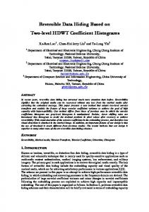
2 H.264/AVC Intra prediction In H.264/AVC intra prediction method [11], a prediction block is formed based on previously reconstructed blocks. There are nine prediction modes for each 4×4 block. The sixteen elements in the 4×4 block (labelled from a to p in Fig. 1.(a)) are predicted by using the boundary pixels of the upper and left blocks which are previously obtained (labelled from A to M). These boundary elements are therefore available in the encoder and decoder to form a prediction reference. For each 4×4 block, one of nine prediction modes can be selected by the encoder. In addition to DC prediction type, numbered as mode 2, where all elements are predicted by (A + B + C + D + I + J + K + L)/8, eight directional prediction modes are specified as shown in Fig. 1.(b). For mode 0 (vertical prediction), the elements above the 4×4 block are copied into the prediction block as indicated by arrows, Fig. 1 (c).
3
Other modes copy adjacent pixels into the prediction block based on their prediction directions. M A B C D E
F
G H
A
B
C
D
I
a
b
c
d
A
B
C
D
J
e
f
g
h
A
B
C
D
K
i
j
k
l
A
B
C
D
L
m n
o
P
A
B
C
D
(a) (b) (c) Fig. 1. 4×4 intra prediction mode (a) labeling of prediction samples. (b) 4×4 intra prediction mode direction. (c) Vertical (mode 0) prediction
The rate distortion optimisation (RDO) technique [12] is used to take full advantage of the mode selection regarding maximising coding quality and minimising data bits. The RDO is applied to all of the 4×4 block intra-prediction modes to find the best one. This approach can achieve the optimal prediction mode decision. The only drawback for using RDO is the computational complexity. Recently, there is more focus on developing the 4×4 intra-prediction mode decision techniques with lower complexity.
3 Suggested scheme The SIPE method consists of an embedding and a extracting procedure. The embedding process includes both computing the prediction errors and embedding the information bits in the shifted prediction errors. Moreover, the data extraction is the reverse of data embedding. The proposed method is explained in the following two subsections.
3.1 Embedding The embedding algorithm is as follows. 1. 2.
3. 4.
The prediction type is selected. It can be selected by RDO or other 4×4 intraprediction mode decision techniques. The prediction blocks are computed from the cover image by using an intra prediction algorithm (as described above). For the blocks without upper or left blocks, the coder uses their upper or left pixels for prediction. The prediction error (PE) blocks are calculated by subtracting the predicted blocks from the cover image block, � � � � �. The number of prediction errors in PE blocks equal to d is denoted by D(d). The value M is found such that D(M) is at a maximum. The following steps
4
5.
6.
7.
(5-6) are carried out for each 4×4 block completely and then iterated for the next block. In the shifting stage, the modified PE block is derived from the PE block by this approach: for each PE block element ��, (expect top-most row and the left-most column of the cover image; � 1 and � � 1), if ��, is larger than M, then the modified PE � ′ �, equals ��, � 1, otherwise � ′ �, � ��, . In the embedding stage, each � ′ �, � � 1 and � � 1� with a value of M is increased by one if the corresponding bit of the data (to be embedded) is one, otherwise it will not be modified. After concealing data in � ′ �, , the embedded PE � ′′ �, is obtained. Finally, the marked image � � is achieved by � � � � � � ′′ .
In fact, the pixels in the top-most row and the left-most column of a cover image are preserved without carrying any hidden data. These pixels are used for recovering the original image and extracting the embedded data from the marked image. These row and column are the same in both the cover and the marked images. It is worth mentioning that, in the coder and the decoder, the raster scan order is used. The gray value of M, the prediction mode and the block size will be treated as side information that needs to be transmitted to the receiving side for data retrieval.
3.2 Detection The following process is used for extracting the secret message from a marked image and also losslessly recovering the cover image. Let the marked image � � be the received image at the decoder. The following steps (1-4) are carried out for each block completely and then iterated for the next block. 1. 2.
3. 4.
The prediction block � of � can be obtained by using the intra prediction algorithm using its upper and left blocks which have been already restored. If the embedded PE block element, � �� �, � � � �, � ��, , is equal to M + 1, it is concluded that the embedded bit is “1”. In this case, � �� �, should be decreased by one to obtain the modified PE block element, e� �, � e�� �, � 1. If � �� �, is equal to M the embedded bit is “0” and � � �, � � �� �, , otherwise there is no embedded data bit and again e� �, � � �� �, . If � � �, � M, then the prediction error ��, is calculated by decreasing � � �, by one, ��, � � � �, � 1, otherwise ��, � � � �, . Finally, the ��, should be added to prediction value ��, to recover the original cover image pixel, ��, � ��, � ��, .
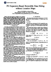
Fig. 2 shows an example of a 4×4 block greyscale image. The encoder scans the cover image block, Fig. 2(c1) pixel by pixel and subtracts the vertical prediction pixels, Fig. 2(c2), from the cover image pixels. In the PE (prediction error) block, Fig. 2(c3), following the computation of all prediction blocks the obtained M is equal to 0 and D(M) in the current block equals 6. Suppose that the bit stream to be embedded is
5
101001. The encoder scans the PE block and all elements larger than 0 are increased by one, Fig. 2(c4), then modified prediction errors equal to 0 are chosen for embedding data.
2 3 6 3
5 3 4 1 6 2 5 3 (c1)
7 8 7 6
3 3 3 3 3
5 2 5 2 5 2 5 2 5 2 (c2)
6 6 6 6 6
-1 0 3 0
0 1 -1 -1 1 0 0 1 (c3)
1 2 1 0
-1 0 4 0
0 2 -1 -1 2 0 0 2 (c4)
2 3 2 0
-1 1 2 2 0 -1 -1 3 4 2 1 2 0 0 2 1 (c5)
2 3 7 3
6 4 4 1 7 3 5 4 (c6)
8 9 8 7
-1 0 1 1 0 -1 -1 2 3 1 0 1
2 5 3 7 3 4 1 8
0 0 1 0 (d5)
3 5 3 6 (d6)
3 5 2 6 2 6 4 8 3 4 1 9
3 5 2 6 3 5 2 6
-1 1 2 2 0 -1 -1 3
-1 0 2 2 0 -1 -1 3
7 7 3 8
3 5 2 6
4 2 1 2
3 5 4 7 (d1)
3 5 2 6 (d2)
0 0 2 1 (d3)
4 2 0 2 0 0 2 0 (d4)
6 6 2 7
Fig. 2. Embedding steps (c1) - (c6) , Detection steps (d1) – (d6)
If the corresponding bit of the secret data is one, the modified prediction value is added by one, otherwise it will not be modified, as shown in Fig. 2(c5). The marked image, Fig. 2(c6), is obtained by adding the embedded prediction errors, Fig. 2(c5), to the prediction pixels, Fig. 2(c2). As described above, the value M (in this example equals to zero) and the prediction mode are treated as side information. The decoder extracts the secret data and obtains the original image block from the marked image block, Fig. 2(d1). The prediction block is computed based on the restored cover image blocks, Fig. 2(d2). The decoder scans the embedded PE block, Fig. 2(d3), which is obtained by subtracting the prediction block from the marked block. If the embedded PE element is equal to 1 and 0, the embedded data bit is “1” and “0”, respectively. In case the embedded PE is equal to “1” or “0”, the modified PE Fig. 2(d4), equals “0”, otherwise it equals the embedded PE. In order to get PE, Fig. 2(d5), if the modified PE is larger than 0, it must be decreased by one, otherwise the PE equals the modified PE. Finally, restored cover image pixel, Fig. 2(d6), is computed by adding PE, Fig. 2(d5), to the prediction pixel, Fig. 2(d2). This example clarifies the simplicity and reversibility of this method. In fact we have three steps in embedding and detecting: calculating prediction error, shifting and embedding. In the detector the prediction block is calculated based on restored cover image blocks and, thus, the prediction blocks in the embedding and detecting procedures are the same. In the encoder, the marked image is achieved by adding the embedded PE to the prediction image block and then, in the decoder, the embedded PE is achieved by subtracting the prediction block from the marked image. When we have the embedded PE block, the modified PE and the PE can be obtained very easily by decreasing the value of the block pixels. Finally, adding PE to the prediction block results in the restored cover image. Hence, all steps are reversible.
6
4 Experimental results The SIPE algorithm was implemented and tested on various standard test images from the UWaterloo database [13]. Also, the results of Lin and Hsueh’s [4], Kamstra and Heijmans’s [6], and Xuan et al’s. [7] methods were compared with the results obtained with this method. This comparison shows that the SIPE method is able of hiding more secret data than almost all methods mentioned in the literature for the same (above 45dB) PSNR. The experimental results of the SIPE method show that the embedded data remains invisible, since no visual distortion can be revealed. It is worth pointing out that the embedded data were generated by the random number generator in MATLAB on a personal computer. Table 1 summarizes the experimental results obtained by this method for the Mandrill, Lena, Peppers, Zelda, Goldhill, Barbara, and Boat images using vertical prediction. For the sake of brevity, only the simple case of one maximum of D(d) is described, because the general cases of multiple maxima of D(d) can be decomposed as a few maximum cases. The payload capacity is increased by using multiple maximum of D(d). In the Right Shifted type, M is equal to 0 and the prediction errors larger than 0 are increased by one. In the Left Shifted type, M is equal to –1 and the prediction errors smaller than 0 are reduced by one. In addition, in the L&R Shifted type, Left Shifted and Right Shifted types are used simultaneously. Table 1. PSNR (dB) and payload capacities (bits) of the test images of the UWaterloo database [13] with different block size (N × N) Right Right L&R L&R Shift type shifted Shifted shifted shifted Ratio N=1 N=4 N=1 N=4 PSNR 51.13 51.1 48.3 48.24 Mandrill 2.12 Payload 7630 6137 15088 12031 PSNR 51.12 51.16 48.58 48.49 Lena 2.58 Payload 28932 22616 52664 42334 PSNR 51.13 51.17 48.49 48.43 Peppers 2.70 Payload 21158 17810 40929 34775 PSNR 51.16 51.13 48.61 48.48 Zelda 2.75 Payload 27120 19977 53474 39201 PSNR 51.26 51.34 48.43 48.36 Goldhill 2.63 Payload 17431 13063 34492 25948 PSNR 51.15 51.19 48.51 48.40 Barbara 2.33 Payload 22409 15680 43682 31167 PSNR 51.12 51.06 48.59 48.49 Boat 2.60 Payload 27522 21735 52543 41591
The experimental results of the L&R Shifted type exhibit that the PSNR of all marked images is above 48 dB.
7
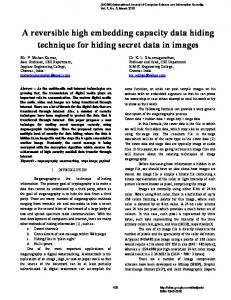
Although in the description of the method only 4×4 blocks were used for embedding and detecting data, other block sizes could be easily used. Fig. 3 shows how the performance of the proposed scheme varies with different block sizes: 1×1, 2×2, 3×3, 4×4, and 8×8. As shown in the figure, the performance of the proposed scheme is increased when the block size is the smallest one (1×1). The smaller the block size, the larger the amount of the embedding information and the more computation time is required. Since in most of image data hiding applications the computation time is not critical, using 1×1 blocks to achieve high capacity and PSNR is desirable. In Table 1, the “Ratio” is the ratio of computation time for embedding process using 1×1 blocks to embedding time using 4×4 blocks. In H.264/AVC, using 4×4 blocks is more effective because the frames are divided into 4x4 blocks for coding and decoding and, furthermore, the execution time is a critical issue in video coding.
Fig 3. Comparison between the embedding capacity in bpp and distortion in PSNR with different block sizes for the Lena image.
Fig. 4 illustrates the performance comparison of the SIPE with the methods reported in [4], [6], and [7] for the Lena image in terms of PSNR (dB) and payload (bpp: bits per pixel). As shown in Fig 4, the SIPE scheme provides high enough bound of the PSNR (above 48dB) with a quite large data embedding capacity, indicating a fairly better performance of the SIPE method. It is worth to mentioning that the selection of the prediction mode is an important step. Fig. 5 demonstrates the effects of the selection mode on capacity and distortion. As an example for the Lena image, vertical prediction has higher capacity with lower distortion.
8
Fig. 4. Comparison between the embedding capacity (bpp) and distortion (PSNR) for the Lena image
Fig. 5. Comparison of embedding capacity versus distortion with different prediction modes for the Lena image
5 Conclusion This paper presents a novel high-capacity reversible data hiding algorithm, called shifted intra prediction error (SIPE), which is based on shift differences between the cover image pixels and their predictions. Large capacity of embedded data (15-120 kbits for a 512×512 greyscale image), PSNR above 48 dB, applicability to almost all types of images, simplicity and short execution time are the key features of this
9
algorithm. The SIPE method is applicable for error resilient solutions in H.264 advanced video coding. Therefore, the SIPE method has several advantages with respect to the methods reported in [4], [6] and [7], in which the suggested algorithms are considered among the best methods in lossless data hiding.
Acknowledgement This work is partially supported by the Spanish Ministry of Science and Innovation and the FEDER funds under the grants TSI2007-65406-C03-03 E-AEGIS and CONSOLIDER-INGENIO 2010 CSD2007-00004 ARES.
References 1. ITU-T Rec. H.264/ISO/IEC 14496-10, “Advanced Video Coding,” Final Committee Draft, Document JVTG050, Mar. 2003 2. Shi, Y.Q., Ni, Z., Zou, D., Liang, C., and Xuan, G., “Lossless data hiding: Fundamentals, algorithms and applications,” in Proc. IEEE Int. Symp. Circuits Syst., Vancouver, BC, Canada, , vol. II, pp. 33–36, 2004 3. Fallahpour, M., Sedaaghi M.H., "High capacity lossless data hiding based on histogram modification," IEICE Transactions on Electronics Express Vol. 4, No. 7 pp.205-210, 2007 4. Lin , C.C, and Hsueh N.L, “Hiding Data Reversibly in an Image via Increasing Differences between Two Neighboring Pixels,” IEICE TRANS. INF. & SYST., Vol.E90–D, NO.12 pp 2053-2059, Dec. 2007 5. Tian, J., “Reversible data embedding using a difference expansion,” IEEE Transactions on Circuits and Systems for Video Technology, pp.890-896, 2003. 6. Kamstra, L., Heijmans, H. J.A.M., “Reversible data embedding into images using wavelet techniques and sorting”, IEEE transactions on image processing vol. 14, no. 12, pp.20822090, 2005 7. Xuan, G., Shi,Y. Q., Chai, P., Cui, X., Ni, Z., Tong, X., "Optimum Histogram Pair Based Image Lossless Data Embedding," Proc. International Workshop on Digital Watermarking (IWDW07), Guangzhou, China, 2007 8. G. Xuan, Y. Q. Shi, C. Yang,, Y Zheng, D. Zou, P. Chai, “Lossless data hiding using integer wavelet transform and threshold embedding technique,” IEEE International Conference on Multimedia & Expo (ICME05), Amsterdam, Netherlands, July 6-8, 2005 9. D.M. Thodi and J.J. Rodriguez, “Expansion embedding techniques for reversible watermarking,” IEEE Trans. Image Process., vol.16, no.3, pp.723–730, 2007 10. M.Kuribayashi, M.Morii, and H.Tanaka, "Reversible watermark with large capacity based on the prediction error expansion," IEICE Trans. Fundamentals, vol.E91-A, no.7, pp.17801790, Jul. 2008 11. Richardson, I. E. G., “H.264 and MPEG-4 Video Compression”, Wiley, pp. 120-145, 2003. 12. Sullivan, G. J. and Wiegand, T., “Rate-distortion optimization for video compression,” IEEE Signal Process. Mag., vol. 15, pp. 74–90, Nov. 1998 13. Waterloo Repertoire GreySet2, http://links.uwaterloo.ca/greyset2.base.html. Last checked on October 27th , 2008