Simulation modeling of manufacturing and other systems has become ... Building Expert, Model Execution Expert, and Model Analysis. Expert. .... this behavior, there is transfer of control from the expert-core ... As in a context free grammar, ..... simulation environment and applied to high autonomy issues in the latest book,.
IEEE TRANSACTIONS ON SYSTEMS, MAN, AND CYBERNETICS-PART A SYSTEMS AND HUMANS, VOL. 26, NO. 1, JANUARY 1996
81
A Knowledge-Based Simulation Environment for Hierarchical Flexible Manufacturing Bernard P. Zeigler, Fellow, ZEEE, Tae H. Cho, and Jer:zy W. Rozenblit, Member, IEEE
Abstract- This article presents an approach to embedding expert systems within an object oriented simulation environment. The basic idea is to create classes of expert system models that can be interfaced with other model classes. An expert system shell is developed within a knowledge-based design and simulation environment which combines artificialintelligence and systems modeling concepts. In the given framework, interruptible and distributed expert systems can be defined as components of simulations models. This facilitates simulation modeling of knowledge-based controls for flexible manufacturing and many other autonomous intelligent systems. Moreover, the structure of a system can be specified using a recursive system entity structure (SES) and unfolded to generate a family of hierarchical structures using an extension of SES pruning called recursive pruning. This recursive generation of hierarchical structures is especially appropriate for design of multilevel flexible factories. The article illustrates the utility of the proposed framework within the flexible manufacturing context.
I. INTRODUCTION
C
OMPUTER simulation is one of the most widely used techniques in manufacturing systems study [ 11-[3]. Rapid modeling of such systems can play a significant role in supporting timely determination of optimal manufacturing strategies in response to changing market requirements. However developing simulation models of large-scale complex systems is an arduous, time-consuming task. Simulation modeling of manufacturing and other systems has become even more demanding due to the incorporation in recent years of intelligent knowledge-based elements into their control functions. For example, expert systems have been developed for solving problems of varying complexities in areas such as planning, scheduling, controlling, maintenance and fault diagnosis [3]-[7]. Such knowledge-based systems present a host of specific requirements on an environment to aid the simulation model builder. Such issues include: Communication Links: Expert and knowledge-based control elements have to interact efficiently with the manufacturing or other processes they control. This requires that there be a systematic way of establishing communication links between expert system elements and other model components for rapid and valid model development.
Distributed Expert Systems: Expert systems may be spatially and functionally distributed. This requires the capability to represent multiple expert system model components, often copies of the same prototypes, within the same simulation environment. ZnterrzqtibiZity: Often, due to cost and resource limitations, only one expert system agent is available to handle requests from multiple sources. In this case, the inferenicing has to be interrupted to process more urgent requests first. Also inferencing may have to pause while waiting for needed process data. Such interruptlresume behavior should be representable in the simulation model. Hierarchical Modular Construction: Expert systems should be treated no differently from other simulation models in building complex models from components in a model base [SI-[lo]. These requirements must be satisfied in order to efficiently develop simulation models with embedded expert systems in a timely, cost-effective and valid manner [ 111. To address these issues, this article presents a framework for embedding expert systems within an object oriented simulation environmenit. The basic idea is to create classes of expert system models that can be interfaced with other model classes. An expert system shell for the simulation environment is developed and implemented in the DEVS-Scheme knowledgebased design and simulation environment. This framework combines artificial intelligence, system theory, and modeling formalism concepts [SI-[lo], [12]. We show how this framework S U P P I D ~ ~ Sthe construction of interruptible distributed experl. systems as modular components of simulations models. We also show how fractal (recursive) architectures for flexible manufacturing that have been previously proposed [ 131 can be specified using a recursive system entity structure concept in DEVS-Scheme. We remark that the framework extends well beyond manufacturing to support simulation modeling of knowledge-based control in many other high autonomy systems [ 141.
11. BACKGROUND
There has been an increasing volume of research that attempts to combine artificial intelligence (AI) and simulation in the last several years [15]-[18]. Expert or knowledgeManuscript received May 7, 1993; revised February 13, 1994 and October based systems have been applied to simulation to support the 23, 1994. This work was supported in part by Motorola Inc., Scottsdale, AZ. modell building process, express behaviors of intelligent agent The authors are with the AI Simulation Group, Department of Electrical components, and aid the modeller to execute and interpret and Computer Engineering, University of Arizona, Tucson, AZ 85721 USA. simulation runs [ 191. Publisher Item Identifier S 1083-4427(96)00050-1. 1083427/96$05.00 0 1996 IEIZE
IEEE TRANSACTIONS ON SYSTEMS, MAN, AND CYBERNETICS-PART
82
A SYSTEMS AND HUMANS, VOL. 26, NQ. 1, JANUARY 1996
ENTITIES
KNOWLEDGE-BASES I
SYNTHESIS-KB
ENTITIES
INFERENCE-ENGWES
inference-engine
CLASSIFICATION-KB
SYNTHESIS-IE
* test-condition * execute-action
CLASFICATIOME
ROBOT-IE
Fig. 1. Class hierarchy of DESE
router-rules
0
0
0
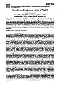
Several knowledge-based simulation shells have been developed. The Knowledge Based Simulation System (KBS) : class or instance variable [20j uses expert systems to assist the simulationist during * :method the entire simulation process. Simulation Craft [21] offers the services of three basic experts embedded in the system: Model Fig. 2. Class hierarchy of rules. Building Expert, Model Execution Expert, and Model Analysis ENTITIES Expert. The behaviors of the objects created for simulation are expressed by production rules in ART-ROSS [22]. DEVS-Scheme [9], [lo], [12] is a knowledge-based s h u l a tion environment that allows a modeller to keep models in an PARAMETERS organized library in modular form, thus supporting the hierarthreshold chical synthesis required in investigating design alternatives. triple ROUTER-FACTS * test-triple The DEVS-Scheme environment is based on two formalisms: discrete event-system specification (DEVS) and system entity structure. The DEVS formalism [8] is a theoretical, well grounded means of expressing hierarchical, modular discrete: class or instrance variable event models. In DEVS, a system has a time base, inputs, *: method states, outputs, and functions. The system functions determine Fig. 3. Class hierarchy of facts. next states and outputs based on the current states and inputs [SI, [9], [23]. The system entity structure ( S E 8 directs the Our framework is based on the distributed expert system synthesis of models from components in a model base. The classes shown in Fig. 1. The most general class is entities SES is a knowledge representation scheme that combines decomposition, taxonomic, and coupling relationships 191, [101. which provides utilities for manipulating instances (objects) Due to its object-oriented multiple inheritance capabilities, for its subclasses. The class entities can be shared among subclasses of existing classes can be readily added to DEVS- all subclasses which belong to their own problem domain. Scheme as desired. The reader is assumed to be familiar with The highest level classes (most general classes) in DES are the basic concepts of DEVS and SES as expounded in the knowledge-bases and inference-engines.The class knowledgebuses is further specialized into synthesis-kb and classijicationgrowing literature in the area [lo]. In the next section we show how to program expert systems kb to distinguish between synthesis expert systems [28] and in an object oriented language and how such expert systems classification expert systems [29], [30], two main types of expert systems and inferencing methods. The corresponding are embedded in DEVS models. two inference engine classes are synthesis-ie and classijicationie. As expert systems for new applications are developed, new 111. EXPERTSYSTEM SHELL FOR SIMULATION ENVIRONMENTclasses may be added to the existing classes shown in Fig The Distributed Expert System Environment (DESE) is de- 1. For example, a class robot-ie required in modeling ausigned and implemented in SCOOPS (Scheme Object Oriented tonomous robots was developed by inheriting and augmenting Programming System) [24j. Distributed expert systems (DES) the features of classijication-ie. can have distributed control (inference engines) and data bases Rules and facts have their own class specialization hierar(rules and facts). DESE is a software package consisting of chies. As shown in Figs. 2 and 3, the leaf nodes represent object classes, methods and other utility functions for modeling some example classes created for modeling of expert systems distributed expert systems. The DES models created under which make decisions for routing transportation devices within the DESE are instances of generic classes developed so as the fractal architecture model to be discussed later. The class to exploit the benefits of object oriented programming such as parameters provides uncertainty management utilities based the ease of reuse, modularity, and extensibility [25]-[27]. on [31j.
-
I
--
-
83
ZEIGLER et al.: KNOWLEDGE-BASED SIMULATION ENVIRONMENT
KNOWLEDGIE-BASES
TABLE I INSTANCEVARIABLES OF CLASSES IN DESE clas5
Instance
ATOMIC-MODELS
-- ind-vim (sigma phase) int-transfn
inference-engine -- objeet-classea
-- aoutputfn t-tmin - We-advancefn
-rUle-class
Usage
variable
* inference new-ohjeets ** make-new-expert
knowledge
I
bases knowledge
* make-copy
* * *
bases knowledge
ATOMIC-EXPERT-MODELS ind-vars (expert-core) make-copy
-
bases inference
kb-mmp. name of the instance of the knowledge base component
- : instance-variables
which is the same as the DES’sname
engines inference
it-ie
points to an inference table which stores the inferencine state
-engines inference
local-
-engines
memory-
I
: method
Fig. 4. Interface of DES to DEVS-scheme.
used to access each DES’sset of fact instances ATOMIC-EXPERT-MODEL
name
The objects involved in the definitions of a DES are instances of knowledge-base, inference-engine, rules and fact classes. An inference-engine instance does not directly access rules and facts. Instead, it refers to an associated knowledgebase which has links to the relevant rules and facts. In this way, the inferencing methods of the class inference-engines or its subclasses are generic (i.e., can be used for rules and facts stemming from a variety of classes). Fig. 1 also shows the instance variables of each class. The roles of instance variables are explained in Table I. The instance variable local-memory-name is used when a copy of a DES is made. This copy can access its own list of facts which is an independent copy of the original DES’s list of facts (this enables the engine to keep track of the distinct inferencing states). The instance variable it-ie points to the inference table which stores the current inferencing information about a DES including fired rules, goal state, attribute list, etc., where the initial value of the attribute lists represents the current dynamic status of the model components being controlled. These (fired rules, goal state, attribute list, etc.) are the contents of the information that should be sent between expert system elements and model components. It is the it-ie or inference table that establishes the static communication links between expert system elements and model components being controlled. The nature of the communication links are static since the model components to be controlled by particular expert system elements are predefined at system design level. When there are multiple sets of expert system elements in the model as the fractal architecture model presented in Section VI, each set of expert system elements can have its own static communication links to corresponding model components. A. InterJacing DESE and DEVS-Scheme:
Atomic-Expert-Models
The interface of DESE to DEVS-Scheme is accomplished by creating classes called atomic-expert-models. This class (multiply) inherits methods and variables from the classes knowledge-bases and atomic-models (Fig. 4). Thus, as illus-
r DEVS-COMPONENT
- EXPERT-CORE I I
1h
INFERENCE-ENG.
OWLWDGE-BASES
YE:
U PI
L Fig. 5. Composition of atomic-expert-model.
trated in Fig. 5, an instance of class atomic-expert-models has both a1 DES (called as expert-core) and an atomic-model (called as DEVS component). These models can be duplicated by invoking the make-copy method which produces isomorphic copies [32]. When a copy of atomic-expert-model is created, the state variables of expert-core are initialized to the original model’s expert-cone name which is extended by the duplicated model name (in order to access different expert system component). The newly created copies of fact instances have names which are extensions of the name of the original model. Rules are not copied. Instead, each copy of the model has pointers to the original rules. Besides the utilities just presented, all the methods and utilities of DEVS-Scheme remain applicable. In this way, inheritance of methods is exploited to extend hierarchical, modular dliscrete-event model construction and simulation to include distributed expert system components. B. Interruptibility of Expert System Models
Recall that an important requirement for embedding expert systems in a simulation environment is to provide intenupt-
84
A: SYSTEMS AND HUMANS, VOL. 26, NO. 1, JANUARY 1996
IEEE TRANSACTIONS ON SYSTEMS, MAN, AND CYBEF3ETICS-PART
AB
AB 6leyel-one
I
I
I
I ABleveLone
AB-dm
I
A
I
AB 6level-two
I
I
A @level-lwo
AB @ level-th ree
B-SW ABOlevel-n I
c
AB
Fig. 6. System entity structure for recursive pruning.
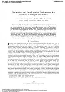
ibility of the DES models. The interrupt capability is needed when an urgent or high priority task arrives while the inference engine is processing a less urgent one. When processing of the current task is interrupted, its state is saved for use when inferencing is resumed later. The nature of saved states .are the value of parameters (or facts of rules) just before the inferencing is interrupted. The values of parameters change as the inferencing process proceeds toward goal states from initial states through several intermediate states. Since these states are represented by different values of parameters, the saved state is the value of parameters of an intermediate state.To implement this behavior, there is transfer of control from the expert-core to the DEVS component after the end of each basic inference cycle. A check is done to see if a high priority external input event has been buffered by the DEVS component since the last check was made. This is similar to cyclic polling of an operating system interrupt. In this context however, the basic inference cycle can be defined as the user desires, for example, as the firing of a single rule, firing of a given number of nules, passage of a predefined simulation time, or the attainmelit of an inferencing subgoal. The cost of interruption lies in two aspects. The first aspect is in computer computation time. Whenever the interrupt occurs, all the values must be saved so that the resuming inferencing process can start from the interrupted states. The second aspect is in simulation time, i.e., the actual delay time of the system due to the interruption of the current process. This delay occurs, however, ma:y be compensated by improved performance, which is the reason for providing interrupt capability. IV. RECURSIVE PRUNING The system entity structure (SES) directs the synthesis of models from components in a model base [9], [lo]. The SES is a knowledge representation scheme that combines the decomposition, taxonomy, and coupling relationships. This section presents a design technique for generating recursive system entity structures, where substructures may contain copies of themselves. An operation called recursive pruning is applied to the SES for generating hierarchical model structures with properties similar to fractals. For example, Fig. 6 shows
A 6 level-n
C6level-n
Fig. 7. PES with recursive pruning.
an SES which specifies the recursive structure of model AB. AB consists of A and B, where B is specialized into C or AB,the root model itself. If we select C at B-spec node in the pruning process, the model AB will have A and C as its subcomponents and no recursive structure is generated. On the other hand, truly recursive pruning is invoked when AB is selected at E-spec node. As in a context free grammar, recursion can be continued to an arbitrary desired depth. Fig. 7 represents the PES resulting from n layers of recursion terminated by the final selection of C from the B-spec node. The figure also shows how a level-matched name extension is generated each time the E-spec node is encountered during pruning process. This enables self-similar models in different levels to be distinguished. Fig. 8 illustrates the hierarchical model represented by the PES in Fig. 7. When there are several recursions in pruning process, it gets more complicated. To alleviate such complexity, we can prune in more easily managed, reusable stages. In delay pruning, decisions can be delayed for later pruning sessions. For example, Fig. 9 shows an intermediate stage in which only the number of recursions of AB and the selection at the Aspec node of level one were decided. The remaining A-spec nodes were left undecided and delayed for later pruning. This intermediate PES was further pruned, eventually to take the form of the PES at the left lower side of the figure. Here all possible selections have been made and the PES is ready for transformation to simulatable form. Delay Pruning is useful in constructing several similar model architectures where only relatively small differences in subsequent pruning are needed. This will be further illustrated in the flexible manufacturing system example to be discussed next.
v.
FRACTAL
ARCHITECTURE MODEL
This section describes the application of DES models and recursive pruning to the fractal architecture for flexible manufacturing introduced by Tirpak et al. [13]. The purpose of this
85
ZEIGLER et al.: KNOWLEDGE-BASED SIMULATION ENVIRONMENT
SES
7
AB @ level-two
I
AB0lwd-o~
A
AB@level-three-
Ai
U
0
I
0 0
rAB@level-n
1
I
AiBIed-n
CBlevel-n
Fig. 9. Dehy pruning.
bfu next layer bfus
...
:atomic models
I
I
:coapledm~
Fig. 8. Model AB pruned to have a recursive structure.
I
I
................................................
example is not to achieve a fully algorithmic development but to provide a framework for showing the utility of the just presented simulation concepts. The fractal architecture to be considered includes multiple expert systems in a family of modular, hierarchically constructed DEVS models. Although this example considers only a limited aspect of the manufacturing process (transporter routing), it generalizes readily to all phases of the manufacturing process. Since expert system components are treated no differently than other DEVS models, once the SES and model base have been constructed, it is relatively easy to generate alternative model architectures.
4
1
.....................
transporters
I I " '
I
muting reqw
*
muting info
........................................mutingrequest ............ .........,
--
A. SES Representation of Fractal Architectures Typically, a flexible manufacturing system (FMS) consists of a hierarchy of several workcells, each containing one or more transporters, sub-cells, etc. Managing the flow of information and control across this hierarchy can be quite complex. Tirpak et. a1 [13] argue that, cast in a fractal, i.e., recursive form, a model of an FMS admits of a natural hierarchical decomposition of highly decoupled units with similar structure
~
materiainow
information flow
Fig. 10. Basic fractal unit architecture.
and control. The objective of such structuring is to manage the structural icomplexity and coordination of an FMS hierarchy by maximizing local functionality and minimizing global control. Moreover. the recurring components can be designed within the object-oriented paradigm so as to maximize reuse across
86
IEEE TRANSACTIONS ON SYSTEMS, MAN, AND CYBERNETICS-PART
A SYSTEMS AND HUMANS, VOL. 26, NO. 1, JANUARY 1996
factory
I
next layer bSus
I
c
'
I
:
I
!
j :
,,' Mu
;hopfloor 1
\
:
workstation 1
...
\
\
:
i
n;
a
i ;
next laver bfus
i
next layer bfus
:: :: ::
:
\
t
; '
: : : ,
: ;
3;
I
workstalion 2 next layer bfus
c
Fig. 11. Fractal architecture pruned to have five BFU's.
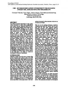
levels. Thus the FMS fractal architecture model represents a hierarchical structure built from elements of a single basic design called a basic fractal unit (BFU). The design of the BFU incorporates a set of pertinent attributes that can fully represent any level in the hierarchy [13]. Fig. 10 depicts a BFU specifically designed to embody the elements which fully describe the structure of any level in the model hierarchy. Included within a BFU is a set of lower layer BFU's whose internal detail is hidden. The
routing controller (transporter router) sees these units as stations to which transfer batches should be delivered. It is the responsibility of transporter routers within the lower layer BFU's to subsequently route the received batches. For illustration, the structure of one of the pruned models constructed for simulation is shown in Fig. 11 (detailed function of each model is described in [14]). The top of the hierarchy is a factory. The factory is composed of two shop floors. The first shop floor (shopfloorl) in turn has
87
ZEIGLER et al.: KNOWLEDGE-BASED SIMULATION ENVIRONMENT
ATOMIC-EXPERT-MODELS
KNOWLEDGE-BASES
INFERENCE-ENGINES
II
I1 t
bfuTspec I
t
ROUTER-RULES I
nl
ROUTER-FACTS I
...
.. div
:s
--
I ma
rOUterm
io
transps
I
coops~
Ill
:inst.needd.as
*
:indicated Un U& provided bylnstanawriables :instanx nri.Me :rn&od
genr
transp
I
in-buf
transd
bfus
11
bfu
out-buf
Fig. 12. Classes in the construction of the expert router.
two workstations, workstation1 and workstation2. Whereas, the second shop floor has two machines without having any workstation. Workstation1 has two machines and workstation2 has just one machine. The transporter router is an expert system model which controls routing of transporters in each BFU. It routes transporters among the lower layer BFU’s, output buffer and input buffer. There are total of five such DES models (one for each BFU) whose inferencing is based on their own sets of facts, responding to the different dynamic conditions encountered at each level (Fig. 11). The router and the rules used by its expert system are depicted in Fig. 12 and Appendix A.
bfu :basic fractal unlt bel : btu and exp. frame ni :neat layer pu :processingunH div :divider routerm : router model
in-but :Input-buffer out-bur : output-buffer transp :bansporter et :experimentalframe genr :generator transd :transducer
Fig. 13. System entity structure for bef (basic fractal unit with experimental frame) architecture.
I
I
IranapOBfac
I
B. Fractal Architecture Modeling The recursive SES for the fractal architecture is shown in Fig. 13. The root of the SES, b e ! which represents the model as being composed of BFU and ef, experimental frame consisting of genr (generator model) and transd (transducer model). Generator provides inputs to BFU, and transd collects the outputs from BFU for the calculation of output statistics. The BFU is specialized into two models, the nl (next lower layer) and ma (machine). The component nl is decomposed into div (transfer batch job divider), routerm (transporter router), io (input/output buffer), transps (transporters) and BFU’s, where transps and BFU’s are broadcast-models, for which the number of components can be selected during pruning. The io is again decomposed into in-io (input buffer) and out-io (output buffer). The fractal SES is pruned to yield a desired model architecture such as shown in Fig. 11. During recursive pruning, recursion stops when a machine ma is selected. Fig. 14 shows the PES for the architecture in Fig. 11. This architecture is just one of many possible that can be generated from the SES (Fig. 13). We can decide on an arbitrary number of hierarchical levels in constructing an architecture by terminating the recursion at the desired depth. Actually the depth need not be uniform. For example, the PES in Fig. 14 has three layers of recursion for the left side and two layers for the right side. The coupling at the BFU level is depicted in Fig. 15.
I
I I I
rn
rnaoestl
mal est1
Fig. 14. Pruned system entity structure of BFU.
The PES in Fig. 14 does not show the experimental frame part of the architecture. There are five BFU’s in this architecture. The root is BFU@fuc (BFU for factory level). The modells at the second level (shop floor level) BFU’s are BFU@lsJD and BFU@sfl. The models BFU@wsO and BFU@wsl are workstation BFU’s within BFU@sfO. There are two transporters in BFU @sfl.All other BFU’s have just one transporter. Self-similar models within different BFU’s are distinguished by the extension attached after the “@” symbol,
IEEE TRANSACTIONS ON SYSTEMS, MAN, AND CYBERNETICS-PART
88
-I
bfu bfus
A SYSTEMS AND HUMANS, VOL. 26, NO. 1, JANUARY 1996
I
VO PORTS: message contents
INPUT PORTS
i l l I
I
irpair that ccf&ts of a model requesting muting and a jobinfo e.g. (wsl @&info)
i
M :transperter model name forsignalinme current trnnspn ia done e.g. tmnsplOwsl OVTPUT PORTS
cut: ajob-info 0
,...
0
...............,
i
.
Job-W : Uob-rype, Job-id, botch-size, scherbrlc) where zhe scherbrle Is Im Of model Mmes
:
i
Fig. 16. U 0 ports and corresponding message contents of transporter router
model.
aut-obb in-ibl
i int-t-ob
I t A
bfU PO* p o n - m : c o m c t i m (message conmu) in-t-ob :input poil from banspoter(leadingrequest) in-ib inputport from bansporter(transfer batches) out-ob :output port lo vanspotem (bansfarbatches) out-t-ob :w$ul port lo muter (routing request)
h z k I lPat fmm
[don;,d
mReC q m f c
W t i :wiprrt Pat to muter .................. * : inforroatian&on
-:materklfbw
Rest of the port co~eetions o r e f o d by r m h g ohme “phinwlporrs Md the comecrions of io model ( w f i g u r e ) .
Fig. 15. DEVS BFU model.
e.g., div@fac, div@s@, d i v e s f l , and so on. These extensions, which are generated during the pruning process, reflect the level and the module they belong to. VI. DISCUSSION AND CONCLUSION
The interruptibility feature developed for the DES environment is well illustrated by the transporter routing expert system. The current positions and velocities of all transporters within a BFU must be known when the transporter controller (router) makes its routing decisions. This position infomation is used to decide the departure time (in addition to the destination) of a transporter. By controlling their departure times collisions among the transporters can be avoided. When necessary, the router model interrupts the inferencing process and sends position and velocity query messages to all the transporters. After obtaining the needed position information it resumes the inferencing process. Not all expert system shells offer this interrupt capability. However, its utility as demonstrated through simulation should suggest the need to include it in real world applications. Alternate structures (reconfigured structures) of the fractal architecture model can be generated through the recursive pruning process. The alternate structures can have different hierarchical levels and different numbers of sub-BFU’s and transporters within a BFU. After pruning, the details of an architecture model can be conveniently initialized prior to simulation. Such rapid prototyping should greatly enhance the ability to investigate alternative architectural solutions to manufacturing problems in a timely manner.
All h e component models in the fractal architecture model base are reusable. Since these models are modular and standalone components, reusability is achieved by specifying their desired coupling in an SES for a given application. To aid the user in understanding the models for valid reuse, complete documentation should be provided of the U 0 ports of models, the message structures on on these ports, and the behavioral description of models (Figs. 16, 17 and the Appendix illustrate such documentation.) In conchsion, we have presented an approach to embedding expert systems within an object-oriented simulation environment that facilitates the creation of classes of expert system model elements that can be interfaced with other model components. We have shown how interruptible distributed expert systems can be defined as modular components of simulations models. Their usefulness in fractal architectures for flexible manufacturing, as proposed in the literature, was illustrated. Simulation results forthis study are available in [14]. Finally, we showed how such an architecture can be specified using a recursive system entity structure. This recursive generation of hierarchical structures is especially appropriate for design of multilevel flexible factories using fractal architecture concepts. However, the framework given in this paper extends well beyond manufacturing to support simulation modeling of knowledge-based control in many other systems for which high autonomy is the desired objective. APPENDIX DESCRIPTIONOF
TRANSPORTER
ROUTERMODEL
The model gets a routing request and sends the routing decision after inferencing the router rules. This router model can control more than one transporters. A. Model Behavior
Initially the model is at passive state. When a inferencing request comes from io model at input port in the model goes to inferencing state. If routerm is at inferencing state when a routing request arrives the routing request is placed in the queue. The inferencing result is sent to a transporter through output port out. The model returns to passive state when
ZEIGLER et al.: KNOWLEDGE-BASED SIMULATION ENVIRONMENT
passive
t 0
I inference
I
Fig. 17. State transition diagram of transporter router model.
inferencing is done and the queue is empty (if queue is not empty it inferences the next request and remains in inferencing state). When the transporter finishes transporting the batch it sends a done signal to routemz at input port in-t. The forward chaining inferencing is performed for inferencing router rules. B. Rule Description The rules are written for rule-ordering combined with context limited conflict resolution strategy. The highest priority rule has the smallest rule number.The parameter “request” is used for context limiting. C. Rule Priorities
1) Route the continuing batches first (continuing batch is the second batch). 2) If there are more than one batches waiting in the queue, route the one at the place where a transporter exists. 3) If there is no continuing batch where a transporter exists, route by FCFS base. In routing FCFS base, if there is a noncontinuing batch (the first batch) whose destination (a place the batch should be delivered) is same as the place of selected continuing batch then route this noncontinuing batch also in routing the selected continuing batch. This case is called as extra-pickup. 4) If there is no continuing batch then route the noncontinuing batch at the place a transporter exists. 5) If there is no noncontinuing batch at the place a transporter exists then route based on FCFS. 6 ) The destination of selected batch is waiting for the second batch (continuing batch) to come then try the next one in the queue. If there is none in the queue then wait until a new routing request arrives. When there are more than one transporters for a router to control in a BFU the router inferences on each transporter based on the above priorities. A single inferencing result is selected based on the following priorities. 1) Select a inferencing result whose requested position is the same as the transporter’s position (if more than one choose the first returned inferencing result). 2) Select the one whose extra-pickup condition is true. 3) If none of above then select the first returned inferencing
result. REFERENCES [l] M. L. Law and W. D. Kelton, Simulation Modeling & Analysis. New York McGraw-Hill, 2d ed., 1991.
89
[2] R. G. Pukin and C. R. Standridge, Modeling and Analysis of Manufacturing Systems. New York Wiley, 1993. [3] H. Pierjreval and H. Ralamboundrainy, “A simulation and learing technique for generatingknowledge about manufacturing systems behavior,” Artificial Intelligence in Operational Research, G. I. Doukidis and R. J. Paul, Eds. New York: Macmillan, 1992. [4] S. D. Wu, “Artificial intelligence and scheduling applications,” Artificial Intelligence; Manufacturing Theory and Practice, S. T. Kumara, Ed. Norcross, GA: Industrial Engineering and Management Press, 1989. [5] A. Kuaiak, “Expert systems and optimization in automated manufacturin.g systems,” Artificial Intelligence; Manufacturing Theory and Practic,e, S. T. Kumara, Ed. Norcross, GA: Industrial Engineering and Management Press, 1989. [6] H. Matwo, J. S. Shang and R. S. Sullivan, “A knowledge-based system for stacker crane control in a manufacturing environment,”IEEE Trans. Syst. Man Cyber., vol. 19, no. 5, 1989. [7] P. J. O’Grady and K. H. Lee, Intelligent Cell Control System for Automasted Manufacturing. New York Taylor & Francis, 1989. [8] B. P. Zeigler, Theory of Modeling and Simulation. New York Wiley, 1976. [9] -, Multifacetted Modeling and Discrete Event Simulation, Orlando, E: Academic, 1984. [lo] -, Object-Oriented Simulation with Hierarchical, Modular Models, San Diego, CA: Academic, 1990. [ 111 S. Narayanan, D. Bodner, U. Sreekanth, T. Vovindaraj, L. McGinnis and C. Mitchell, “Research in object-oriented manufacturing simulations: An ass’essment of the state of the art,” Personal Communication of Manuscript, 1993. [12] J. W. Rozenblit, J. W. Hu, T. G . Kim and B. Zeigler, “Knowledge-based design ;and simulation environment (KBDSE): Foundation concepts and implementation,”J. Oper. Res. Soc., vol. 41, no. 6, 1990. [13] T. M. Tirpak,S. M. Daniel, J. D. LaLonde and W. J. Davis, “A note on a fractal ;architecture for modeling and controlling flexible manufacturing systems,” IEEE Trans. Syst. Man Cyber., vol. 22, pp. 564-567, June 1992. [ 141 T. Cho, “A hierarchical, modular simulation environment for flexible manufacturing system modeling,” Ph.D. Dissertation, University of Arizona, Tucson, 1993. [15] J. G. Vaucher, “Views of modeling: Comparing the simulation and AI approaches,” in Proc. SCS Multicon$ ArtiJicial Intelligence, Graphics, and Sinwlation, pp. 3-7, 1985. [16] T. I. Oren and B. P. Zeigler, “Artificial intelligence in modeling and simulation: Directions to explore,” Simulation, vol. 48, no. 4, pp. 131-134, 1987. [17] S. G. Tzafatas, “Knowledge engineering approach to system modeling, diagnosis, supervision and control,” Simulation of Control Systems, Selected Papers from the IFAC Symposium, pp. 15-22, 1987. [18] C. Tsatsoulis, “A review of artificial intelligencein simulation,”SIGART Bulletin, vol. 2, no. 1, 1991. [19] R. O’Keefe, “Simulation and expert systems-A taxonomy and source examples,” Simulation, vol. 46, pp. 10-16, 1986. [20] Y. V. R. Reddy and M. S. Fox, “The knowledge-based simulation system,” IEEE Software, vol. 3, pp. 26-37, Mar. 1986. [21] V. B. Rax and J. B. Baskaran, “Simulation craft: An artificial intelligence approach to the simulation life cycle,” in Proc. Summer SCS Con$, pp. 773-778, 1986. [22] M. E. McFall and P. Klahr, “Simulation with rules and objects,” in Proc. 1986 Winter Simulation Con$, pp. 470-473, 1986. [23] A. I. Concepcion and B. P. Zeigler, “The DEVS formalism: Hierarchical model ‘development,” IEEE Trans. Software Eng., vol. 14, no. 2, pp. 228-241, 1988. [24] Texas Instruments, Austin, Texas, USA, PC-Scheme Manual, 1987. [25] A. Yonezawa and M. Tokoro, Object-Oriented Concurrent Programming. Cambridge, MA: MIT Press, 1987. [26] S. E. Kkene, Programming in Common Lisp Object-Oriented Systems, Norwell, MA: Addision-Wesley, 1988. [27] S. R. Alpert, S. W. Woyak, H. J. Shrobe and L. F. Arrowood, “Objectoriented programming,” IEEE Expert, pp. 6-7, 1990. [28] D. MclDermott, “RI: A rule-based configurer of computer systems,” Art$ Intell., vol. 19, no. 1, 1982. [29] B. G. IBuchanan and E. H. Shortliffe, Rule-Based Expert-Based Programs: The MYCIN Experiments of the Stanford Heuristic Programming Project. Reading, MA: Addison-Wesley, 1984. [30] R. Lindsay, B. G. Buchanan, E. A. Feigenbaum and J. Lederberg, Application of Artificial Intelligence for Chemical Inference: The DENDRAL Project. New York McGraw-Hill, 1980.
[31] B. P. Zeigler, “Some properties of modified dempster-shafer operators in rule based inference systems,” Znt. J. General Systems, vol. 14, pp. 345-356, 1988.
90
IEEE TRANSACTIONS ON SYSTEMS, MAN, AND CYBERNETICS-PART
[32] T. G. Kim, “A knowledge-basedenvironment for hierarchical modeling and simulation,” Ph.D. Dissertation, University of Arizona, Tucson, 1988.
Bernard P. Zeigler ( M 87SM87-F’94) received the B. Eng. Phys. fromMcGil1University,Montreal, QuBbec, Canada, in 1962, the M.S.E.E. from the Massachusetts Institute of Technology, Cambridge, in 1964, and the Ph.D. from the University of Michigan, Ann Arbor, in 1969. He is currently Professor of Electrical and Computer Engineering, University of Arizona, Tucson. He has published over 200 journal and conference articles in modeling and simulation,knowledge based systems and high autonomy systems. His first book, Theory of Modeling and Simulation (Wiley, 1976) is regarded as one of the foundational works in the field. A second book, MuZrifacetied Modeling and Discrete Event Simulation (Academic Press, 1984), was given the outstanding simulation publication award by TIMS College on Simulation in 1988. Concepts developed in earlier works are implemented in the DEVS simulation environmentand applied to high autonomy issues in the latest book, Object-oriented Simulation with Hierarchical, Modular Models: Iarelligenr Agents and Endomorphic Systems (Academic Press, 1990). Dr. Zeigler’s research has been supported by federal agencies, including NSF, NASA, USAF, and the U.S. Army, as well as industrial sponsors, including Siemens, McDonnell Douglas, and Motorola. He is currently heading a multidisciplinary team to demonstratean innovative approach to massively parallel simulationof large scale ecosystem models within NSF‘s HPCC Grand Challenge initiative.
A SYSTEMS AND HUMANS, VOL. 26, NO. 1, JANUARY 1996
Tae Ho Cho received the Ph.D. degree in electrical and computer engineering from the University of Arizona, Tucson, in 1993, and the B.S. and M.S. degrees in electrical engineering from Sungkyunkwan University, Seoul, Korea, and the University of Alabama, Tuscaloosa, respectively. He is an Assistant Professor in the Department of Computer Science, Kyungnam University, Masan, Korea. His research interests are in the areas of modeling and simulation, factory automation, intelligent control, artificial intelligence for simulation methodology.
Jerzy W. Rozenblit (M’90) is an Associate Professor in the Department of Electrical and Computer Engineering, University of Arizona, Tucson. He specializes in modeling and computer simulation, knowledge-based system design, and artificial intelligence. His principal research activities focus on the development of expert, computerbased environments for engineering design support. Dr. Rozenblit serves as Associate Editor of ACM Transactions on Modeling and Computer Simulation and a reviewer for National Science Foundation, Research Council of Canada, and Australia. His research in design has been supported by NSF, SRC, Siemens, McDonnell Douglas Corporation, and U.S. Army Research Laboratories,where he was a Research Fellow. In 1994.1995, he was Fulbright Senior Scholar and Visiting Professor at the Institute of Systems Science, Johannes Kepler University, Austria.