6-2 .-
.
Simulation Environment for Semiconductor Technology Analysis Ch. Pichler, R. Plasun, R. Strasser, and S. Selberherr Institute for Microelectronics, TU Vienna, Gusshausstrasse 27-29, A-1040 Vienna, Austria Phone +43/1/58801-5239, FAX +43/1/5059224, e-mail
[email protected] A programmable simulation environment for semiconductor technology analysis is presented. The SIESTA project sets out t o combine the advantages of a comfortable, intuitive visual user interface with the flexibility and versatility of a high-level programming language. It is designed to provide a set of framework services to ensure a straight-forward definition of complex technology analysis tasks. Special emphasis has been put on establishing in an object-oriented fashion a uniform and easy-to-use interface for applications and extensions supplied by the user. LISP objects are used t o represent basic entities like process steps, process flows, experiments, and agents for design of experiments (DOE),response surface modeling (RSM), and optimization and fitting modules. The integration of heterogeneous process and device simulation tools is based on PIF [l]as a common tool data exchange format. Nevertheless, native tool data formats are supported as well, ensuring maximum flexibility in the choice of simulation tools for a particular task or a t a particular site, while minimizing computation overhead and numerical errors due t o excess data conversion. The automatic generation of split points both for sequentially and simultaneously initiated runs and the parallel and distributed execution of independent split tree branches allow a fast computation of large-scale experiments. A persistent run data base keeps the results (output files and extracted data) of each completed step and prevents unnecessary re-computations. A r c h i t e c t u r e and Components. The implementation of the simulation environment is based on the VISTA framework [2] and it’s extension language VLISP, an enhanced version of XLISP. A class of evaluable entzty (EVE) objects has been defined t o provide uniform access t o basic services like process flow simulation and RSM evaluation as well as t o complex tasks specified by the user. They establish a.standardized interface t o perform evaluations and can be defined in terms of existing EVES in a nested manner. E.g., the minimization of the bulk current for a given process is encapsulated in an object that is evaluated for a set of initial value vectors for the optimizer generated by the DOE module or by a simple LISP loop. Fig. 1 shows the main functional components and their interactions. All communication between objects and between the framework and external executables works on an asynchronous basis to allow simultaneous control of a number of independent tasks within the simulation environment. The optimizer module [4] performs optimizations under non-linear constraints and nonlinear parameter estimations, the DOE module creates experiment inputs according t o standard design schemes, and the RSM module generates and evaluates polynomial response surfaces of up t o second order. Both the DOE and RSM modules support a number of transformations to adequately represent non-linear systems. The run controller uses a process flow representation [3] t o build the desired devices. It generates split trees and controls parallel computation of simulation jobs on the network. A number of framework tools provide gridding and geometry services t o ensure data consistency and facilitate data exchange between different simulators. Note that both batch and interactive operations are fully supported. A batch file can be used to run complete analysis tasks over night, t o customize the environment and t o define new objects, or t o load and initiate an analysis while monitoring and controlling it via the visual user interface. Applications. To illustrate the use of high-level commands t o specify a complex TCAD task, fig. 2 shows the definition of a central composite circumscribed design (CCC) for the bulk current and the threshold voltage for the N-device as functions of implantation energies and doses for a standard Si-gate CMOS process [5]. The Def ine-Task statement creates an EVE from a process flow description, Eve-Def ine-Control statements mark specific process parameters as control variables for subsequent evaluations. The Eve-Set-Control initializes nominal values and ranges of all control variables as well as transformations t o use. The process consists of 79 fabrication steps and has been simulated on a mixed cluster of UNIX workstations using PROMIS, TSUPREM4, and MINIMOS simulators. Fig. 3 shows part of the visual user interface during parallel computation of the runs created by the DOE module. Conclusions. A highly programmable environment designed t o support the most complex of TCAD tasks has been presented. The concept of evaluable entities provides a sound basis for the definition and execution of nested and aggregate analysis problems. Heterogeneous simulators and framework services are effectively encapsulated and form the basic building blocks for higher-level applications in process design, process analysis and process optimization. F. Fasching et al., “A PIF implementation for TCAD purposes”, SISPED IV, 1991, pp. 477-482 S. Halama et al., “The Viennese Integrated System for Technology CAD Applications”, Technology C A D Systems, Springer 1993, pp. 197-236 Ch. Pichler et. al., “Process Flow Representation within the VISTA Framework”, SISPED V, Springer 1993, pp. 25-28. Ch. Pichler et. al., “TCAD Optimization Based on Task-Level Framework Services”, SISPED VI, Springer 1995, pp. 70-73. G. Schumicki and P. Seegebrecht, Prozefitechnologie, Springer 1991, pp. 370-380.
147
) t I [
Visual User Interface ;; dofino a l l 0 crntrol and rpsponsoa vsrinblos ;; n" and vpriablo i n the procsss flow
by specifying praoss stop
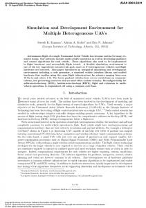
Figure 2: Batch file t o define and submit high-level tasks. Control and response variables are selected from an existing process flow description. A set of experiments is generated by the DOE module and submitted to the run controller for execution.
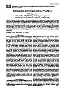
Figure 1: Overview of basic functional components. Evaluable entities (EVE) provide a uniform interface for computation requests, agents connect external services with the framework. Both agents and EVES are VLISP objects.
Ireate substrate Sxidation Deposit resist Expose Develop Etch oxide Strip resist Grow screening oxide N-well-implant Well diffusion
Geometry segmentlist--daaa Doping Boron Doping Phosphorus Doping active Boron Doping active Phosphorus
Strip oxide Grow oxide Deposite nitride Deposit resist Expose Strip exposed Etch nitride
E
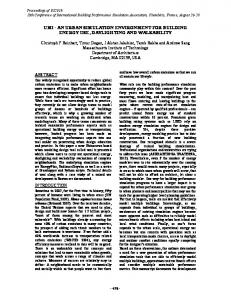
Figure 3: Part of the visual user interface during parallel, distributed computation of 17 runs generated via a half-factorial central-composite design for a complete CMOS process. 9 runs are active, while the remaining 8 are waiting for d a t a to become available at split points. Direct access is provided to data generated at each step.
.
Acknowledgment. Our work is significantly supported by Austria Mikro Systeme AG, Unterpremstatten, Austria; Christian Doppler Gesellschaft, Vienna, Austria; Digital Equipment Corporation at Hudson, USA.
148