Jan 14, 2011 - multi-hop wireless network in which the nodes automatically ... Afterward, the main features of protocols applied in each layer are a briefly.
5 A Layered Routing Architecture for Infrastructure Wireless Mesh Networks Glêdson Elias, Daniel Charles Ferreira Porto and Gustavo Cavalcanti Federal University of Paraíba Brazil 1. Introduction Wireless Mesh Networks (WMN) is a new technology that promises improved performance, flexibility and reliability over conventional wireless networks. WMNs are easy to deploy and have self-configurable and self-healing capabilities. In essence, a WMN is a dynamic, multi-hop wireless network in which the nodes automatically establish and maintain connectivity among them. Thus, routing protocols have a fundamental role by providing paths to allow communication between non-neighbor nodes and so keep up best routes. One of the most important goals for routing protocols developed for WMNs is to reduce the routing overhead and improve network scalability. The WMN’s architecture defines two types of nodes: mesh client (MC) and mesh router (MR). They can play different roles in the network, forwarding packets in behalf of other ones or just using the network resources. Depending on such roles, three types of WMNs can exist: client, infrastructure and hybrid (Akyldiz et al., 2005). A client WMN is just an ad hoc network built only by MCs. The infrastructure WMN (IWMN) is the most common type, being formed by a fixed, dedicated group of MRs, which builds a wireless backbone, providing a coverage area for keeping connected mobile MCs, even when they are moving (Fig. 1). In IWMNs, MCs cannot forward packets and besides cannot communicate directly with each other. Finally, in a hybrid WMN, the backbone is built by mobile and fixed devices. Hence, both MCs and MRs can forward packets, although only MRs can connect the backbone to other networks. The routing facilities required by WMNs are already present in protocols developed for ad hoc networks. So, ad hoc routing protocols like DSR (Johnson et al., 2004), AODV (Perkins, C. et al., 2003) and OLSR (Clausen, T. & Jacquet, P., 2003) have been applied in several WMN projects (Chen, J. et al., 2006) (Bicket, J. et al., 2005) (Tsarmpopoulos, N. et al., 2005). However, such protocols do not perform very well in WMN and the throughput drops as the number of nodes increases (Akyldiz, I. F. et al., 2005). One of the major problems of such routing protocols is that they do not use properly the infrastructure provided by WMNs. Therefore, taking into account WMN features, research efforts have been focused on enhanced them or designing new protocols such as RA-OLSR (Bahr, M., 2006), HWMP (Bahr, M., 2006) and AODV-ST (Ramachandran, K. et al., 2005).
www.intechopen.com
110
Wireless Mesh Networks
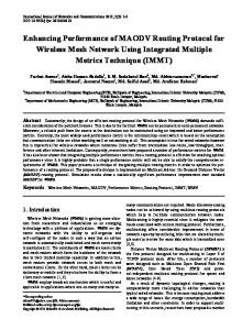
Mesh Router Static Mesh Client Mobile Mesh Client
Fig. 1. Infrastructure wireless mesh network As evinced in (Chen, J. et al., 2006) and (Hossain, E. & Leung, K., 2008), improved scalability in terms of the number of nodes in the network may be achieved reducing routing overhead. Hence, a scalable routing protocol can be applied to small as larger number of nodes without exhaust network resources with excessive sending of control messages. An interesting approach to address routing problems is to split routing capabilities into a layered routing architecture. So a specialized strategy can be applied to address problems for each layer to improve routing protocol´s scalability. In such a context, this chapter presents the efforts of network research group at Federal University of Paraíba in Brazil on specifying a scalable, layered routing architecture, called Infrastructure Wireless Mesh Routing Architecture (IWMRA) (Porto, D.C.F. et al., 2009), which is specifically designed considering IWMN’s features. The proposed architecture allows separating routing concerns into a three-layered architecture and designing of a specialized protocol for each layer. The main strengths and innovations of the proposed architecture are the separation of routing concerns in three independent layers and the differentiation of routing strategies for MR and MCs to reduce signaling overhead, adopting proactive and reactive strategies for static and mobile nodes, respectively. The remainder of this chapter is organized as follows. The related works and context are presented in Section 2. Then, the proposed three-layered routing architecture is presented in Section 3. Afterward, the main features of protocols applied in each layer are a briefly described in Sections 4, 5 and 6. The initial results of performance evaluations are described in Section 7. Finally, the Section 8 presents the concluding remarks and future work.
2. Related work and context As WMNs are essentially a dynamic multihop wireless network, the topology can change very fast. Thus, the routing protocols play an important role providing needed paths to allow communication among the nodes. The wireless routing protocols have to be aware to topological changes caused, for instance, by node movement. These topological changes may happen in the neighborhood of the nodes or in the links of path between them. Then, the routing protocol has to restore or compute a new path for keeping the communication.
www.intechopen.com
A Layered Routing Architecture for Infrastructure Wireless Mesh Networks
111
Among of a variety of routing protocols applied to WMNs, the OLSR´s first version (here, simply indicated as OLSR) is an example of modular core architecture with well defined neighborhood discovery and topology dissemination processes. Nevertheless, these processes are integrated in OLSR´s specification but not as independent protocols. However, for the OLSR´s second version (OLSRv2) (Clausen T. et al., 2010), the neighborhood discovery process was separated from its specification as an independent protocol called Neighborhood Discovery Protocol (NHDP)(Clausen T., C. Dearlove & J. Dean, 2010). The NHDP is intended to be used for routing protocols to provide continued tracking of neighborhood changes and allows routing protocols to access neighborhood information. The OLSRv2 specification retains the same basic mechanisms and algorithms of OLSR (topology dissemination and routing calculation process), while using a more flexible signaling framework that refers NHDP as responsible for manage neighborhood information. It must be emphasized that OLSR´s neighborhood process is basically identical to NHDP, except that NHDP uses a new packet structure and address compression technique defined by the packetbb (Clausen, T., et al., 2009) specification. Due the clear separation of OLSR´s processes, it is not too difficult to make a performance evaluation between OLSR and IWMRA´s protocols. Taking into account that NHDP and OLSRv2 are not available for the adopted simulator yet, the presented performance evaluation has just compared the protocols of IWMRA and the processes of OSLR. In order to make possible to understand the reasoning presented in the performance evaluation, a brief description of the OLSR processes (neighborhood discovery and topology dissemination) is presented at this point. In OLSR, in all nodes, the neighborhood discovery process periodically sends HELLO messages in broadcast at a regular time interval (2 seconds, by default). Note that MRs and MCs periodically send HELLOs but they do not forward them. A given node X declares other node Y as neighbor whenever X receives a HELLO from Y. In complement, a given node X declares the neighborhood with other node Y as lost when X does not hear three HELLOs from Y (6 seconds by default). To disseminate the neighborhood data through the network OLSR uses an optimized link state algorithm. Each node in the network employs an algorithm to select a set of neighboring nodes to retransmit its Topology Control (TC) messages. This set of nodes is called the multipoint relays (MPR) of that node. Any node which is not in the set can read and process each TC but do not retransmit. Note that, MRs and MCs can be selected as MPR of a node, according to MPR´s selection algorithm. Thus the OLSR reduces the number of rebroadcasting nodes over conventional flooding. The node sends its TC messages in broadcast at a regular time interval, 5 seconds by default, but the MPRs have to rebroadcast it in up to 0.5 seconds.
3. Infrastructure Wireless Mesh Routing Architecture The Infrastructure Wireless Mesh Routing Architecture (IWMRA) splits routing concerns into a layered routing architecture specifically designed taking IWMNs features. An application scenario, already depicted in Fig. 1, includes a set of fixed MRs, planned to provide a continuous coverage area, and also a set of fixed or mobile MCs. In this initial version of the architecture, all nodes have just one wireless interface and links are bidirectional.
www.intechopen.com
112
Wireless Mesh Networks
As already mentioned, in IWMN’s architecture, the MRs and MCs play different roles where only MRs are responsible to build a wireless backbone and forward network traffic, while MCs just uses network resources. Since the MRs are fixed devices, they can be connected directly to power source, unlike the MCs which are mobile devices and have constrained power supply provided by batteries (Akyldiz et al., 2005)(Zhang, Y. et al., 2006). These IWMN’s features are explored by IWMRA to reduce control message overhead and increase network scalability. To achieve its goals, the IWMRA splits routing functionality into three independent layers: neighborhood, topology and routing (Fig. 2). In each layer, an independent protocol has been designed to handle specific features of IWMNs. Each protocol provides to the upper layer a couple of well defined services. By separating the functionality in layers, the architecture enables further adaptations. The neighborhood layer is defined by SNDP protocol (Elias, G. et al., 2009). Briefly, the neighborhood layer is responsible to detect the presence and status of directly reachable neighbors, keep track of neighborhood changes and alert the topology layer whenever a change is detected. The neighborhood layer may also detect the metric of the link, which is used by upper layers to calculate the overall path cost and select the best routes. The topology layer is defined by MLSD protocol (Porto, D. C. F., 2010). Based on a flooding approach, the topology layer efficiently disseminates neighborhood information to all MRs over the network, allowing the MRs to build a topological map of the network. The topology layer is responsible to keep accurate topological information and synchronize databases among the MRs. It also alerts the routing layer whenever a topological change is detected for the routes to be updated. Finally adopting a proactive and a reactive approaches, the routing layer compute and configure the best routes for all nodes.
Fig. 2. IWMRA layers and its respective protocols SNDP adopts a hybrid, collaborative signaling strategy, in which MRs employ a proactive, timer-based signaling approach, whereas MCs make use of a reactive, event-based signaling approach. MLSD is a low-overhead link-state dissemination protocol. Unlike current proactive routing protocols applied in WMNs, such as OLSR, MLSD employs an event-based approach with a reliable message delivery strategy and a flooding control in order to reduce the message overhead. In the routing layer, IWMP is a multiple routing, hybrid protocol, which is under refinement. IWMP makes use of information provided by topology layer to build a graph and to calculate the best paths using the SPF algorithm (Dijkstra, E.W., 1959). It is important to emphasize that topological information is only stored and handled by MRs. Thus, MCs have to request routes to neighbor MRs, which can promptly answer to such requests.
www.intechopen.com
A Layered Routing Architecture for Infrastructure Wireless Mesh Networks
113
As a proof of concept, the following sections introduce the main insights and concepts of protocols that compose the IWMRA. Then, simulation results of the neighborhood and topology layers are presented and compared to similar functionalities provided by the OLSR protocol.
4. Neighborhood layer - SNDP (Scalable Neighborhood Discovery Protocol) SNDP is a scalable neighborhood discovery protocol, which has been specifically designed taking into account architectural features of IWMNs. Based on such architectural features and in order to reduce control message overhead, SNDP adopts a hybrid, collaborative signaling strategy. On the one hand, the proposed signaling strategy is said to be hybrid because MRs and MCs adopt distinct signaling approaches. On the other hand, the proposed signaling strategy is said to be collaborative because MRs and MCs work together to detect the presence and absence of nodes. Considering that MRs have unlimited power supply, they employ a proactive, timer-based signaling approach, which uninterruptedly and periodically sends messages even when there does not exist any node in their transmission ranges. In contrast, as MCs have limited power supply, they adopt a reactive, event-based signaling approach, which sends messages as a consequence of receiving other ones from MRs in their transmission ranges. The next sections briefly describes the signaling approaches adopted by MRs and MCs, and also how they work together to manage neighborhood among nodes. Note that, the SNDP can only operate on IWMNs that adopt bidirectional links among all nodes and provide continuous connectivity within the coverage area of the wireless backbone. 4.1 Neighborhood discovery SNDP is employed to detect the presence and status of neighbor nodes in IWMNs. As previously mentioned, in IWMNs, MCs do not communicate directly with each other. In such scenario, the communications among MCs are mediated by MRs. Thus, MCs do not need to detect other ones as neighbors. Therefore, MCs have to detect MRs as neighbors, while MRs ought to detect MRs and MCs. Due to such distinct neighborhood discovery requirements, SNDP adopts a hybrid, collaborative signaling strategy. The MRs adopts a proactive, timer-based approach, where periodically they send HELLO messages in broadcast even when do not exist nodes in their transmission ranges. Such an approach allows an MR to be promptly detected as neighbor by any other MR or MC that comes into its transmission range. The MR signaling rate is regulated by a protocol parameter, which by default is 2 seconds. Notwithstanding, the MCs adopts a reactive, event-based approach, where they send HELLO messages in broadcast as responses to other ones, previously received from MRs in their transmission ranges. Such an approach allows an MC to be detected as neighbor by any MR in its transmission range. Note that a given MC only generates a HELLO immediately after detecting a given MR as neighbor. Thus, although MRs send periodic HELLOs, MCs only react to the first HELLO detected from neighbor MRs. Considering the proactive, timer-based approach, two MRs require the exchange of a pair of HELLOs in order to recognize their neighborhood in both directions. Hence, as illustrated in Fig. 3a, each one declares the other one as neighbor after receiving the first periodic HELLO message from the other one.
www.intechopen.com
114
Wireless Mesh Networks
In a similar way, the neighborhood between MRs and MCs are established exchanging HELLOs. Although, the MCs only reacts to first HELLO sent by the MR. Usually, as also illustrated in Fig. 3b, the MR proactively sends a HELLO (arrow 1), and, in turn, the MC reactively sends a HELLO as response (arrow 2). a)
b) HELLO
HELLO
1
MR
1
MR
MR
MC
2
2
HELLO
HELLO
Fig. 3. MR-MR and MR-MC discovery process Beside of that, the signaling approaches adopted by MRs and MCs have to integrate mechanisms to handle transmission problems that causes message loss. In MRs, the proactive, timer-based signaling approach just handles transmission errors by simply resending the HELLO message in the next time interval. In MCs, the reactive, event-based signaling approach deals with transmission errors by adopting a confirmed service, in which MRs must acknowledge in their succeeding HELLO the reception of HELLOs sent by MC, as illustrated in Fig. 4.
HELLO
1
MR
2
MC
HELLO
3 HELLO [Ack MC]
Fig. 4. MR-MC discovery process with acknowledgement Thus, in case of message loss, the robustness of the process relies on immediately after detecting a neighbor MR, an MC must reply with a HELLO message for each one received from that MR, until it receives an acknowledgment sent by the MR. Note that, the acknowledgement is indicated by just including the MC’s address in the MR’s HELLO message, which contains the list of MCs from which the MR has received HELLOs during its last signaling interval (around 2 seconds). 4.2 Neighborhood loss When a node is declared as neighbor, SNDP needs to monitor the neighbor node in order to detect the instant in which the neighborhood is lost. Once more, SNDP adopts a hybrid strategy for detecting and managing neighborhood loss. On the one hand, as MRs periodically sends HELLOs, MCs adopt a timer-based approach. On the other hand, as MCs reactively send HELLOs, MRs adopts a notification-based approach.
www.intechopen.com
115
A Layered Routing Architecture for Infrastructure Wireless Mesh Networks
As MCs adopts the timer-based approach, when an MC declares an MR as neighbor, it also configures an expiration time, which by default is 2 seconds. Then, whenever an MC receives a HELLO from the neighbor MR, it just updates the expiration time. If an MC goes out of the transmission range of a neighbor MR, it will not receive HELLOs from that MR, and so, the neighborhood entry associated with that MR expires. At this moment, the MC declares the neighborhood as lost. In the notification-based approach, as shown in Fig. 5, MCs ought to notify MRs about the neighborhood that has been lost. To do that, immediately after detecting the neighborhood loss, the MC broadcasts a HELLO, including the notification that the neighborhood with the MR has been lost. However, since the connectivity between the source MC and the target lost MR is no longer available, the notification-based approach requires collaboration among intermediary MRs, which forwards the notification to the lost MR.
[TTL 2]
[TTL 1]
A
3
B
2
C
[TTL 3] 1
MC-X
lost MR-A
X
Fig. 5. Notification process SNDP employs a bounded flooding technique to limit the notification area. Note that notifications do not generate additional signaling messages because it piggybacks on periodic HELLOs of intermediary MRs. To limit the notification area, each notification has a TTL (Time to Live) field, which indicates the number of hops that the notification can reach. By default, the TTL field is 3 hops. When an intermediary MR receives a notification, it must decrement the TTL before broadcasting the notification in its next HELLO. If the TTL reaches zero, the intermediary MR does not forward the notification. When the notification reaches the target lost MR, it just declares the source MC as lost. As a result of rebroadcasting notifications, the bounded flooding can make intermediary MRs and the target lost MR to receive replicated notifications. Hence, each notification generated by a given source MC to a lost MR has a sequence number field that enables the MRs detect and discard replicated ones. Due transmission errors, a given MC may not receive a HELLO broadcasted by its neighbor MR. In such a case, as a mean to avoid erroneously declaring the neighborhood as lost, the MC and MR have to cooperate, as depicted in Fig. 6. On the MC’s side, after expiring the neighborhood entry associated with its neighbor MR due to error transmission (arrow 1), the MC broadcasts a HELLO with the notification (arrow 2), but internally it does not declare the neighborhood as lost. Instead of that, the MC just waits for a hold time interval (default 0.5 seconds). The MC can only declare the neighborhood as lost if it does not receive a HELLO from the MR during the hold time interval.
www.intechopen.com
116
Wireless Mesh Networks
On the MR’s side, after receiving the notification directly from the MC (arrow 2), it immediately broadcasts in advance its HELLO (arrow 3), making possible to the MC to keep its neighborhood with the MR. Hence, when HELLOs sent by MRs are subjected to transmission errors, the notification process avoids MCs to erroneously declare the neighborhood with MRs as lost.
HELLO
1
MR
2
MC
HELLO
3 HELLO
Fig. 6. Avoiding the neighborhood loss 4.3 Additional improvements for SNDP When the density of MCs is relatively low throughout the wireless backbone, it is common some MRs do not have MCs as neighbors. In such cases, MRs broadcast HELLOs only with the purpose of keeping the neighborhood with other MRs. In order to reduce signaling load, SNDP specifies a low signaling rate, which by default has a time interval of 32 seconds. The low rate is only adopted by a given MR when it and its neighbor MRs do not have neighbor MCs. To do that, a flag in MRs’ HELLO informs when a given MR has MC neighbors. As a consequence, each MR can adopt two signaling rates. The low signaling rate (each 32 seconds) when the own MR and its neighbor MRs do not have neighbor MCs, and otherwise, the high signaling rate (each 2 seconds).
5. Topology layer – MLSD (Mesh Network Link State Dissemination Protocol) MLSD is a low-overhead link state dissemination protocol, which has also been designed taking into account architectural features of IWMNs. It defines how to spread and maintain consistent and updated information about network topology, allowing the MRs to build a topological map of the network making possible to routing layer build best routes. Considering that in IWMNs the backbone is built only by MRs, MLSD defines that the topological information is only managed by them. As a consequence, only MRs can send and process link state update messages (LSU). Despite of the MCs do not process or send LSUs, they also store topological information. However, the topological information maintained by MCs is just the links with its neighbor MRs, which are informed by neighborhood layer. As already mentioned, when an MC needs to communicate to other nodes, it must use the services provided by routing layer to request and configure a route. In order to reduce the message overhead caused by link state messages, MLSD employs an event-based approach with a reliable message delivery strategy and a flooding control. By adopting an event-based approach, the MRs sends small incremental update messages only when topology changes. Therefore, to ensure the consistency of topological information in all MRs the MLSD also adopts reliable flooding, which uses a positive implicit
www.intechopen.com
117
A Layered Routing Architecture for Infrastructure Wireless Mesh Networks
acknowledgment with retransmission strategy to deploy the update throughout the backbone and a synchronization process to fully update new MRs. Beside of that, MLSD controls flooding by adopting time-slots which are automatically configured among neighbors MRs to help avoiding exhaust network resources due excessive events or retransmissions. The next sections presents a concise description of dissemination process with positive implicit acknowledgment, synchronization and time-slot configuration approaches adopted by MLSD to manage topology among the nodes. Likewise SNDP, MLSD can only work on IWMNs that adopt bidirectional links among all nodes and provide continuous connectivity within the coverage area of the backbone. 5.1 Topology dissemination – positive implicit acknowledgment Once the neighborhood layer makes available neighborhood information, based on a flooding approach, the topology layer is responsible for disseminating such information (called link state advertisement - LSA) to all MRs over the network. Each MR broadcasts in their LSUs one or more LSAs (by default, up to 128). The LSAs flooded by all MRs are employed to derive the network topological database, which is identical for all MRs. Each LSA may define one of two operation types, link discovery (ADD) or link loss (REM) and it is assigned with unique sequence number to allow identifying if it is duplicated or outdated. In the event-based approach, the MRs broadcasts each LSA in the LSU only once. Due transmission errors, a given MR may not receive a LSU broadcasted by its neighbor. In such a case, as a mean to avoid inconsistencies in topological database, the MRs adopts a flooding with positive implicit acknowledgment with retransmission as illustrated in Fig. 7. A given MR-A that broadcasts a LSA in its LSU (Fig. 7a) assures that it has been effectively delivered to a neighbor MR-B, which is indicated as forwarder for such LSA, when the MRB rebroadcasts the same LSA, in its own LSU, to another neighbor MR-C (Fig. 7b). Since the LSU broadcasted by MR-B is received by all neighbors, it can also work as an acknowledgment to MR-A. Therefore, MR-C must also rebroadcast the LSA, at least once, in order to acknowledge the MR-B, even though it has no other neighbors MRs (Fig. 7c).
a)
b)
c)
FW {B}
A
FW {C }
B
x Mesh Routers
C
A
B
FW { }
C
B
C
x
x Mesh Client
A
LSU
Forwarders List
FW{ }
Fig. 7. Flooding with positive implicit acknowledgment Each LSA have a list of forwarders which are address of the neighbors MRs that must rebroadcast it. As also illustrated in Fig. 7, when a LSA is generated in response to neighborhood layer update of a given MR-A, it defines all its neighbors MRs as forwarder to such LSA. When MR-B receives a LSA from neighbor MR-A, it defines all its MR neighbors as forwarders to such LSA, except the one from which the LSA was received (MR-A). It is important to emphasize that when all LSA are successfully delivered and acknowledged, all MR broadcasts its LSU only once. Thus, no additional message is needed
www.intechopen.com
118
Wireless Mesh Networks
and the total LSUs employed is the same that a conventional flooding. However, the positive implicit acknowledge avoid need flooding LSA throughout the backbone again when transmission problems causes message loss. As depicted in Fig. 8, when the MR-B broadcasts a new LSA in its LSU, for instance adding a new link with a given MC-Y, it indicates all its neighbors MRs as forwarder to such LSA. Nevertheless, transmission problems may cause message loss to a given neighbor MR-C (Fig. 8a). After broadcasting the LSU, MR-B internally configures an expiration time to retransmit the LSA which is sufficient to all its neighbors of MR-B also rebroadcast it. The section 5.3 describes how retransmission time is calculated. During the time waited for retransmit the LSA, the MR-B receives the acknowledgment by MR-A, however, as MR-C lost the LSU sent from MR-B, it will not rebroadcast the LSA (Fig. 8b). When the retransmission time expires the MR-B rebroadcasts the LSA, although only the MR-C is indicated as forwarder to LSA (Fig. 8c). As a consequence, MR-C must rebroadcast the LSA. However, despite of the MR-A also receives the LSU, it is not identified as forwarder to such LSA and do not sends the message again. Consequently, only the MR-C rebroadcasts the LSA and acknowledges the MR-B (Fig. 8d). a)
b) FW { }
FW {A,C}
A
B
C
A
B
C
Y
Y
c)
d) FW { }
FW {C}
A
B
C
Y
A
B
C
Y
Fig. 8. Message loss causes retransmission. As already mentioned, each LSU may carry up to 128 LSAs. Since each update has a list of forwarders that has to acknowledge the MR source, the LSA must adopt a compressed packet format to avoid LSU get too large due repetition of MRs’ address list. In the LSU, instead of a list of forwarders for each update there is only one list, which may includes the address of all neighbors MRs indicated as forwarder (usually up to 4) for at least one update carried in the packet. Besides, each LSA can carry more than one update, which are set with unique sequence number generated by its MR source to make possible detect and discard outdated ones. The updates with identical MR source and identical operation code (ADD/REM) are grouped per LSA. Therefore, each LSU actually can carry up to 128 updates, regardless if all of them belong to only one LSA, or if there are 128 LSAs with one update. Thereafter, a bitmap is built to match each update to the forwarders list, enabling the receiving neighbors MRs to derive if they are forwarder for each update. A concise view of most important fields in LSU is presented in Fig. 9. When a given MR-B has to broadcast a LSU, it builds a forwarder list based on updates to send. Then, it also includes compacted LSAs with all updates from the same MR and same operation (ADD).
www.intechopen.com
A Layered Routing Architecture for Infrastructure Wireless Mesh Networks
119
Finally a bitmap matches each update in LSA with the forwarders list. As the forwarders list has two elements, each update must be represented for two bits in bitmap. Hence, for the first update (B ADD X #3), the bitmap defines that it must be forwarded by MR-A (first element in forwarders list) but not by MR-C (second element in forwarders list). The second update (B ADD Y #4) must be forwarded only by MR-C and, the third (B ADD Z #5), must be forwarded by both MR-A and MR-C. The bitmap is built in a group of octets and the remaining bits must be filled with 0’s.
Fig. 9. Concise view of compacted fields in MR-B’s LSU. 5.2 Synchronization process The incremental updates are mostly applied to links between MRs and MCs. Notwithstanding, whenever links among neighbors MRs are removed or discovered it also triggers a database cleaning or database synchronization respectively, to ensure that all MRs’ database reflect the current topology state. On the one side, a database cleaning is trigged whenever a link between two MRs is lost. When a given MR crashes, its neighbors MRs have to broadcast an update removing the link lost. However, such link loss may also split the backbone into distinct sets of nodes. Thereafter, each neighbor MR of the crashed node disseminates an update across all reachable MRs. Whenever an update removing a link between two MRs is processed, internally, each MR performs a connectivity test building a connected set, enabling the MR detect and clean all links of unreachable MRs. On the other side, a synchronization of topological database is trigged whenever a link between two neighbors MRs is discovered. When a given MR-B adds a new link with a given MR-A, beside the discovered neighbor, several others nodes may become reachable. Therefore, the neighbors MRs must exchange their topological databases in order to let know possible new links reachable through each other. To exchange the databases, each MR retrieves all stored updates and set the discovered neighbor MR as forwarder for all of them in the next LSU. Hence, at the moment of a given MR-B discovers a neighbor MR-A, it retrieves all links stored in its database, including the one just discovered, and sets MR-A to forward them in the next LSU to send (Fig. 10a). In turn, MR-A may receives the LSU sent by MR-B regardless the neighborhood layer has been detected the neighbor MR-B yet. As MLSD assumes that all links are bidirectional, the MR-A adds the link with MR-B in advance, retrieves all links stored in its topological database and sets MR-B to forward them in the next LSU to send (Fig. 10b). Note that, the updates retrieved from MR-A’s database and the forwarding updates that acknowledges MR-B goes together in the same LSU broadcasted by MR-A. Finally, the MR-B broadcasts
www.intechopen.com
120
Wireless Mesh Networks
another LSU with the new updates received but without forwarder set for them, as a mean to acknowledge MR-A (Fig. 10c). It’s important to note that due the dissemination process forwards new links across all reachable nodes, they also will be added to all other MRs, synchronizing all databases. a)
FW {A} LSA B{ADD A,...} LSA ....
A
b)
B
FW { } LSA A{ADD B,...} LSA ...
c)
A
B
A
B
FW {B} LSA B{ADD A,...} LSA A{ADD B,...} LSA ...
Fig. 10. Topological database exchanging. 5.3 Time-slot based flooding control The IWMNs also supports mobile MCs. Consequently mobile MCs often cause changes of the MRs’ neighborhood. Moreover, transmission problems like collisions may lead MRs to retransmit messages. For instance, the hidden terminal problem rises when a given MR broadcast a LSU with updates and all of its neighbors MRs has to forward them. In such a case, all neighbors MRs will receive the LSU close to same moment and may broadcast them very close or at the same time causing collisions in MR source, and therefore, retransmissions which can drastically increase the overhead generated by link state updates. To handle excessive events or retransmissions the MLSD employs time-slots automatically configured among neighbors MRs. In such an approach, a LSU sent by a given MR configures its neighbors MRs to broadcast their LSUs in distinct moments (Fig. 11a.).
Fig. 11. Time-slot configuration. As also illustrated in Fig. 11, when a given MR-A detects a neighborhood change, it schedule the update to broadcast within a LSU in the first slot (Fig. 11b). During this time, all events detected will be scheduled to be sent in the same LSU. When the LSU is broadcasted, the forwarder list is built based on neighbors MRs and the updates to send. Then, both neighbors MR-D and MR-C receive the LSU and evaluate the order they appear in forwarder list to schedule the slot they must use to transmit the update. Besides, after broadcasts a LSU an MR-A schedules a retransmission time for the updates sent, considering the time expected to all neighbors rebroadcast them and a multiplier consisting of number of LSUs need to disseminate all updates (Fig. 11b), which is usually one. To avoid the retransmission time get too long the multiplier can only grows up to 5.
www.intechopen.com
121
A Layered Routing Architecture for Infrastructure Wireless Mesh Networks
Note that, when an update is acknowledged, its retransmission is unscheduled. Hence, if all updates were successfully delivered and acknowledged no additional message is sent. It is important to cite that the time slot value is a configurable parameter in MLSD and the value adopted is calculated taking into account the features of wireless technology. For instance, in 802.11 we suggest 0.03125s which is obtained considering bit rate, inter-frame times and maximum message size. In addition, by defining different moments for neighbors MRs broadcast the LSU, MLSD reduces the chance of collision in the source MR and so retransmissions, leveraging the chance of the message being successfully delivered, while handle successive events in a short time interval grouping them in the same message.
6. Routing layer – IWMP (Infrastructure Wireless Mesh Protocol) In the routing layer, a multiple routing, hybrid protocol called IWMP is under refinement. To discover routes, the topology and routing layers have to cooperate. On the MR’s side, IWMP makes use of proactively information provided by the topology layer to build routes. On the MC’s side, the MCs do not have full topology information, and therefore, they have to reactively request routes to neighbor MRs, which can promptly answer to such requests. Since MRs are the only allowed to forward packets in IWMN, each one gets a graph constituted only by MR nodes from topology layer and then uses the SPF algorithm (Dijkstra, E.W., 1959) to build best routes to all other MRs, afterwards the links with neighbors MC are added. Hence, when topology layer notify the routing layer of a new update related to a link with an MC, it can be processed without recalculate all routes. However, whenever MRs’ graph is updated, then all the best routes have to be recalculated. On the MC’s side, in IWMP, all MCs adopt a reactive approach. Thus, when an MC needs a route to other nodes it broadcasts a route request for its neighbor MRs (Fig 12a). Hence, all neighbors MRs responds immediately, in unicast, because they already have the route proactively configured (Fig. 12b). Thereafter, an MC can choose the best route (Fig. 12c). a)
b)
A X
B
c)
C X? Y
A X
B
A
C X! Y
X
B
C Y
Fig. 12. MC’s reactive route setup process. As already mentioned, the IWMP is an ongoing work, and therefore, its facilities still under refinement. For instance, how to connect the IWMN to Internet through multiple gateways and load balance scheme to adopt are topics under development.
7. Performance evaluation The performance evaluation of SNDP and MLSD was contrasted to OLSR's processes by adopting a simulation-based performance evaluation. All simulation scenarios consider a full mesh topology defined by a grid of 10×10 stationary MRs, which defines a rectangular coverage area of 1.04 Km × 1.04 Km, where stationary or mobile MCs move around
www.intechopen.com
122
Wireless Mesh Networks
adopting the random waypoint model without thinking time and all nodes have an 802.11b wireless interface configured to 100m of range. Besides, the simulation scenarios have varied the number and the speed of MCs. In all protocols their speed ranges from 0 to 20 m/s. For SNDP, the number of MCs varies from 0 to 500 nodes totalizing 340 scenarios while MLSD has initial results from 0 to 100 MCs in sum of 48 scenarios. For each simulation scenario, average values of the evaluated performance metrics were calculated based on several simulation experiments, considering a relative estimation error of 5% and a confidence interval of 95%. Together, all simulation scenarios required around 4800 simulation experiments, which were conducted using NS-2 (Fall, K. et al. 2008) together with the UM-OLSR implementation (Ros, J. F., 2008). The performance metric evaluated was the message overhead, which considers the total messages sent by all nodes during the evaluation time of simulation (2840s). The smaller the message overhead, the more scalable is the corresponding protocol because the transmission channel will not be saturated with control messages. As a way to show the general SNDP and MLSD behaviors, this chapter only presents the performance gains in scenarios with four speed configurations including an average of 10 m/s, varying uniformly between 0 and 20 m/s. 7.1 Performance evaluation of neighborhood layer In OLSR's neighborhood discovery process all nodes (MR/MC) periodically send HELLOs in a constant rate. Hence, the neighborhood message overhead raises as the number of nodes increases, because more nodes will send HELLOs. However, OLSR’s message overhead is independent of the speed of the nodes and, in the Fig. 13, all its curves are overlapped. a)
b)
Speed (m/s)
Relative gains %
Number of MCs 0
100
200
500
0
94
50
67
83
10
94
18
23
29
15
94
6
8
10
0-20
94
42
56
70
Fig. 13. Message overhead of SNDP and OLSR’s neighborhood process. Nevertheless, the performance of SNDP evinced by the curves in Fig. 13a, reveals interesting outcomes of the hybrid strategy adopted. As MRs periodically send HELLOs in a high or low rate, depending on the density of MCs in the network, in SNDP, the MRs message overhead is strongly reduced in scenarios with a small number of MCs (less than 30). In such scenarios, several MRs adopt a low signaling rate due to the absence of neighbor MCs. Hence, as the number of MCs increases, the probability of MRs adopting a high signaling rate increases. Once the SNDP high signaling rate and the OLSR signaling rate are equal, the MRs message overhead of both tend to be similar as the number of MCs increases up to 30 MCs.
www.intechopen.com
123
A Layered Routing Architecture for Infrastructure Wireless Mesh Networks
Analyzing the message overhead generated by stationary MCs (0m/s), in OLSR, like MRs, all MCs also periodically send HELLOs. In contrast, in SNDP, MCs do not periodically send HELLOs. In SNDP, message overhead is basically constant and independent of the number of MCs. When contrasted with OLSR, as can be seen in Fig. 13b, SNDP reduces in almost 83% the message overhead in a presence of 500 MCs. Conversely, as evinced by level of the curves in 10m/s and 15m/s, the MCs speed has an important impact on the SNDP message overhead. The higher is the speed, more neighborhood detection and loss events are generated, and so, the higher is the SNDP message overhead. Such a behavior is a consequence of the reactive signaling approach adopted by MCs. Simulations evince that SNDP reaches the OLSR message overhead when MCs speed exceeds 20 m/s. An important result was revealed when the speeds varies from 0 to 20m/s. As also showed in Fig. 13b, the curve has values close to best performance of protocol, and for 500 MCs the gain compared to OLSR reaches 70%. 7.2 Performance evaluation of topology layer In OLSR’s topology management process, the MPRs selection algorithm reduces the number of rebroadcasting nodes. However, the total of MPR nodes are not essentially minimal to coverage all backbone (Clausen, T. & Jacquet, P., 2003). Hence, MPRs selection algorithm may chooses more rebroadcasting nodes than the minimum to provide the coverage area. Besides, each TC can carry up to 64 links per MR but, by default, only 4 TCs can be sent per packet, totalizing up to 256 updates per OLSR packet. Hence, when a MPR has to forward TCs from more than 4 nodes, more packets are immediately sent, in order to deliver all TCs. Therefore, as evinced in Fig. 14a, the OLSR’s message overhead at 0m/s rises as the total of nodes increases, because more MPR can be selected, then will periodically send and forward more OLSR packets with TCs. It is important to evince that, to conduct a fair comparison, only OLSR packets with at least one TC was considered in performance evaluation. Even when the packet carries 4 TCs it was counted as only one message. a)
b)
Speed (m/s)
Relative gains %
Number of MCs 0
10
50
100
0
100 100 100
99
10
100
63
58
75
20
100
46
62
76
0-20 100
90
69
69
Fig. 14. Message overhead of MLSD and OLSR’s topology dissemination process. The speed of MCs has also a large impact on OLSR’s topology message load, because as the node moves around even more MPR are selected, then more nodes sends and forward packets.
www.intechopen.com
124
Wireless Mesh Networks
Analyzing the curve of MLSD when the MCs are stationary (0m/s), it shows that the number of stationary MCs has an insignificant impact in message overhead. The reason is the event-based approach adopted by MLSD. When events are not detected no message are sent, resulting in gains of 100% compared to OLSR, as illustrated in the Fig. 14b. Nevertheless, when mobile MCs are present, the faster the MCs moves, the more events are detected increasing the message overhead, as shown by the level of the curves in 10m/s and 20m/s, and therefore, the number of mobile MCs and their speed impacts in message overhead. However, unlike OLSR, the message overhead grows slowly in higher speeds and many MCs, presenting gains up to 76% even with 100 mobile MCs moving at 20m/s, with similar overhead at 10m/s. Such a behavior is an effect of the time-slot approach adopted. When new updates are sent, the MRs will wait for its neighbors MRs rebroadcast them in their LSU before retransmit another message, as explained. However, the retransmission time calculated considering the number of LSUs to send. Hence, when the number of events grows the MR may use more then one LSU disseminate all of them. Consequently the MR will also wait more time before retransmit them again, accumulating new updates per packet and avoiding disseminate many messages with few updates in a short time. When MCs moves with speeds varying from 0 to 20m/s, the curve still reveals a good performance of MLSD with gain of at least 69% compared to OLSR, as showed in Fig 14b.
8. Concluding remarks and future work The simulation results considering the message overhead evince that both protocols SNDP and MLSD have excellent performance when contrasted with OLSR, especially considering static scenarios, unveiling gains of 94% and 100% for SNDP and MLSD respectively. On the neighborhood layer, considering mobile scenarios, the hybrid collaborative approach of SNDP shows a good performance in average mobility, when the speeds varies from 0 to 20m/s with at least 42% of gain, and a comparable performance when MCs adopt speeds superior to 15 m/s. However, it is also important to note that nowadays it is uncommon to find real scenarios with a large number of highly mobile MCs. Therefore, considering the evaluated metrics, SNDP has an excellent performance in typical IWMNs scenarios. On the topology layer, the performance evaluation turns out expressive gains of MLSD’s event-based approach, in all evaluated scenarios. Indeed, even the worst case of MLSD (20m/s) still has better outcomes, in terms of message overhead, than OLSR’s best case (0m/s). The results evince the effectiveness of the strategies adopted by both protocols SNDP and MLSD. Such results show a well-tuned, layered routing architecture has the potential to drastically reduce message overhead, and so, improve scalability of IWMNs. As future work, in neighborhood layer, new simulations considering new metrics are still need. For instance, to evaluate the load in terms of bytes. Moreover, in topology layer, although rigorous experiments have been realized to validate the convergence and consistence of databases, a formal proof still important and must be conducted to further studies. Additionally, a detailed study about convergence time and also new simulations considering scenarios with many MCs are needed. At last, as already mentioned, in routing layer additional features are still under investigation. When the protocol stack is fully implemented, a performance evaluation contrasting other protocols and considering a new set of metrics like aggregate throughput and routing overhead will be conducted.
www.intechopen.com
A Layered Routing Architecture for Infrastructure Wireless Mesh Networks
125
9. References Akyildiz, I. F.; Xudong, W. & Wang, W. (2005). Wireless mesh networks: a survey, Computer Networks, Vol. 47, No. 4, March 2005, pp. 445-487, ISSN 1389-1286 Johnson, D.B., Maltz, D.A. & Hu, Y.C. (2003). The Dynamic Source Routing Protocol for Mobile Ad Hoc Networks (DSR), April 2003, pp. 1-111. IETF draft Perkins, C., Belding-Royer, E. Das, S. (2003). Ad-Hoc On-Demand Distance Vector (AODV) Routing, July 2003, pp. 2-37. IETF RFC 3561. Clausen, T. and Jacquet, P. (2003). Optimized Link State Routing Protocol (OLSR), October 2003, pp 1-75. IETF RFC 3626 Chen, J. and Lee, Y.Z. Maniezzo, D. & Gerla, M. (2006). Performance Comparison of AODV and OFLSR in Wireless Mesh Networks, MedHocNet'06, pp 271-278, Lipari, Italy, June 2006, IEEE Bicket, J. et al., (2005). Architecture and evaluation of an unplanned 802.11b mesh network. Proceedings of 11th annual international conference on Mobile computing and networking, pp 31-42, ISBN 1-59593-020-5, Cologne Germany, September 2005, ACM, New York Tsarmpopoulos, N., Kalavros, I. & Lalis, S. (2005). A low-cost and simple-to-deploy peer-topeer wireless network based on open source Linux routers, Tridentcom 2005, pp. 9297, ISBN 0-7695-2219-X, Trento Italy, February 2005, IEEE Bahr, M., (2006). Proposed Routing for IEEE 802.11s WLAN Mesh Networks. 2nd Annual International Workshop on Wireless Internet, pp. 5, ISBN 1-59593-510-X, Boston, USA, August 2006, ACM, New York, NY, USA Ramachandran, K. et al., (2005). On the design and implementation of infrastructure mesh networks”, IEEE Workshop on Wireless Mesh Networks (Wimesh), pp. 12, Santa Clara, CA, September 2005, IEEE Hossain, E. & Leung, K., (2008). Wireless Mesh Networks: Architectures and Protocols, Springer Science, ISBN 978-0-387-68838-1, New York, USA Porto, D.C.F. et al., (2009). A Layered Routing Architecture for Infrastructure Wireless Mesh Networks. Proceedings of the 2009 Fifth International Conference on Networking and Services, pp 366-369, ISBN 978-1-4244-3688-0, Valencia Spain, April 2009, IEEE Clausen T., C. Dearlove & P. Jacquet (2010). The Optimized Link State Routing Protocol version 2, April 2010, pp 1-82, IETF draft Clausen T., C. Dearlove & J. Dean (2010). Mobile Ad Hoc Network (MANET) Neighborhood Discovery Protocol (NHDP), July 2010, pp 1-84, IETF draft Clausen T., C. Dearlove, J. Dean & C. Adjih (2009). Generalized Mobile Ad Hoc Network (MANET) Packet/Message Format, February 2009, pp 1-57, IETF draft Zhang, Y. and Luo, J. & Hu, H. (2006). Wireless mesh networking: architectures, protocols and standards, Auerbach Pub, ISBN 0-8493-7399-9, Boca Raton FL, USA Elias, G., Novaes, M. Cavalcanti, G. & Porto, D. (2009). A Scalable Neighborhood Discovery Protocol for Infrastructure Wireless Mesh Networks, Advances in Mesh Networks 2009, pp 132 – 137, ISBN 978-0-7695-3667-5, Athens Greece, August 2009, IEEE
www.intechopen.com
126
Wireless Mesh Networks
Porto, D. C. F., (2010). A Link State Dissemination Protocol for Infrastructure Wireless Mesh Networks, Master Thesis, March 2010, Federal University of Paraíba (in Portuguese) Dijkstra, E.W., (1959). A Note on Two Problems in Connexion with Graphs, Numerische Mathematik, Vol. 1, pp. 269-271, 1959, Springer Fall, K. et al., (2008). The NS manual, available in http://www.isi.edu/nsnam/ns/doc Ros, J. F., (2008). Masimum UM-OLSR, http://masimum.dif.um.es/?Software:UM-OLSR
www.intechopen.com
Wireless Mesh Networks Edited by Nobuo Funabiki
ISBN 978-953-307-519-8 Hard cover, 308 pages Publisher InTech
Published online 14, January, 2011
Published in print edition January, 2011 The rapid advancements of low-cost small-size devices for wireless communications with their international standards and broadband backbone networks using optical fibers accelerate the deployment of wireless networks around the world.
The wireless mesh network has emerged as the generalization of the conventional wireless network. However, wireless mesh network has several problems to be solved before being deployed as the fundamental network infrastructure for daily use. The book is edited to specify some problems that come from the disadvantages in wireless mesh network and give their solutions with challenges. The contents of this book consist of two parts: Part I covers the fundamental technical issues in wireless mesh network, and Part II the administrative technical issues in wireless mesh network,. This book can be useful as a reference for researchers, engineers, students and educators who have some backgrounds in computer networks, and who have interest in wireless mesh network. It is a collective work of excellent contributions by experts in wireless mesh network.
How to reference
In order to correctly reference this scholarly work, feel free to copy and paste the following: Gledson Elias, Daniel Charles Ferreira Porto and Gustavo Cavalcanti (2011). A Layered Routing Architecture for Infrastructure Wireless Mesh Networks, Wireless Mesh Networks, Nobuo Funabiki (Ed.), ISBN: 978-953307-519-8, InTech, Available from: http://www.intechopen.com/books/wireless-mesh-networks/a-layeredrouting-architecture-for-infrastructure-wireless-mesh-networks
InTech Europe
University Campus STeP Ri Slavka Krautzeka 83/A 51000 Rijeka, Croatia Phone: +385 (51) 770 447 Fax: +385 (51) 686 166 www.intechopen.com
InTech China
Unit 405, Office Block, Hotel Equatorial Shanghai No.65, Yan An Road (West), Shanghai, 200040, China Phone: +86-21-62489820 Fax: +86-21-62489821