High performance microprocessor execution cores require multi-ported register tiles (RF) with single-cycle readlwrite. High fan-in or wide dynamic circuits are ...
22.4
A Leakage-Tolerant Dynamic Register File Using Leakage Bypass with Stack Forcing (LBSF) and Source Follower NMOS (SFN) Techniques
Stephen Tang, Steven Hsu, Yibin Ye, James Tschanz, Dinesh Somasekhar, Siva Narendra, Shih-Lien Lu, Ram Krishnamurthy and Vivek De Microprocessor Research, Intel Labs, Hillshoro, OR, USA
Abstract Clock frequency of a multi-ported, 256X32h dynamic register file in a lOOnm technology is improved by 50%, compared to the best dual-V, (DVT) design, using LBSF and SFN leakage-tolerant circuit techniques for LBL and GBL. Total transistor width of the full LBSF design is the smallest. I. Introductinn High performance microprocessor execution cores require multi-ported register tiles (RF) with single-cycle readlwrite. High fan-in or wide dynamic circuits are typically used for local (LBL) and global (GBL) bitlines to meet the aggressive delay and area requirements. However, noise tolerance of wide domino gates degrades rapidly with technology scaling as transistor subthreshold leakage increases exponentially [I]. Although circuit robustness can be recovered by upsizing the keeper at the dynamic node and by reducing skew of the static stage, the resulting performance loss is too large. Conditional keeper schemes [2], pseudo-static local bitlines [3] and a fully static dual-VT register tile [4] have been reported previously for improving performance and leakage tolerance of wide domino gates and register files. In this paper, we propose two techniques, Leakage Bypass with Stack Forcing (LBSF) and Source Follower NMOS (SFN), to improve speed and robustness of wide dynamic circuits. We evaluate the effectiveness of using LBSF and SFN in leakage-sensitive parts of a 256X32h multi-ported dynamic register tile design in a lOOnm dual-VT technology. Delay, energy, total transistor width and leakage tolerance are compared with a conventional dual-VT (DVT) design.
II. LBSF and SFN Leakage-Tolerant Circuits Dynamic RF hitcells, driving the 16-wide LBL, and a domino mux, driving the 8-wide GBL, are the key leakage-sensitive and performance-critical circuits in the 256X32b 4-read, 4write ported register file with single-ended read-select and bitline signaling (Fig. 1). The 1000pm long GBL in M 4 spans the lengths of all 8 hanks in the array, and thus presents a large interconnect load to the domino mux. Skewed static stages, that merge two LBL‘s per bank, drive the mux inputs. A 2@ clocking scheme is used with full time borrowing at the boundary. A 8-bit address per readlwrite port is decoded in the previous cycle to generate the readlwrite select signal at the ‘3, edge. Read delay from @, edge to data at output of the static inverter driven by GBL determines clock cycle time. Noise immunities of the wide dynamic circuits used for driving LBL and GBL degrade as VT is lowered because of excessive leakage in the hitline pull-down devices and worsening trip point of the static stage. In DVT designs, leakage-sensitive devices are made high-VT to achieve a DC noise robustness of at least 10% of supply voltage (Vcd with minimal performance impact (Fig. Ib). Hence, they cannot take advantage of the large drive currents available from lowV, devices in a dual-V, technology. In the LBSF scheme, the LBL pull-down device MO (Fig. Za) in the hitcell is replaced by two series-connected devices M I and M2 (Fig. 2b) to force a 2-stack in the bitline leakage path through the keeper, regardless of the value stored in the cell. This reduces bitline leakage because 2-stack device leakage is significantly smaller than leakage of a single device [ 5 ] . In addition, leakages of M2 and M3 are fully bypassed through the PMOS keeper devices inserted at the stack nodes SI & S2, thus forcing zero drain-source voltage (VDs) across M I . Bitline
320
0-7803-7310-3/02/$17.00 02002 IEEE
leakage path through the LBL keeper is then eliminated, regardless of stored value, read-select voltage and VT. Therefore, performance-critical devices can be made 10w-V~ without impacting robustness. In the SFN scheme, LBL is predischarged and evaluation is performed by pulling up the bitline through a source follower NMOS (M4)device in the bitcell, driven by the read-select signal (Fig. 2c). The storage cell drives a PMOS (MS)and the.LBL transitions when stored value is 0. The static NAND for two-way LBL merge is replaced with a static NOR, followed by an inverter which drives the GBL mux. Bitline leakage is smaller because rise in the predischarged LBL voltage due to leakage through the ,444 devices reduces their gate-source voltages (VGs) and induces reverse body-source (VBs) biases to Cut off further leakage. Hence, SFN allows low-Vr devices to be used for LBL evaluation with minimal impact on robustness. Delays of LBSF and SFN LBL are 16% and 14% better, respectively, than DVT LBL for a DC noise robustness requirement of 10% Vcc (Fig. 3). Clearly, delay at the robustness limit is much worse when leakage-sensitive devices are made 10w-V~ (LVT) in the original design. Improved noise tolerances of LBSF and SFN are exploited to improve LBL delay by using low-VT, reducing keeper size and increasing static stage skew. LBSF is also used to improve leakage tolerance of the 8-wide domino OR driving the GBL (Fig. 4). Hence, delay of LBSF GBL is 44% better than DVT GBL. under identical robustness constraints (Fig. 5).
m. Comparisons of Register File Designs Register file designs, with DVT, LBSF and SFN for LBL and GBL, are optimized for minimum energy at different clock frequency targets, subject to identical robustness constraints. Using LBSF for LBL improves clock cycle time by 1470, compared to the hest DVT design, at equal energy. Additional 22% delay improvement is achieved by using LBSF for GBL as well (Fig. 6). Energy and total transistor width of the full LBSF design are 37% and 47% smaller, respectively. Although LBSF uses more transistors in the hitcell and the GBL mux, it achieves the same delay as the best DVT design with smaller transistor sizes. Using SFN for LBL improves delay by 10% and energy is 24% smaller than the best DVT design (Fig. 7). But total device widths are comparable since large PMOS and NMOS are needed in the hitcell. Combining SFN LBL with LBSF GBL provides delay and energy improvements comparable to a full LBSF design. However, total transistor width of the full LBSF design is the smallest (Fig. 8). Performance gains of LBSF and SFN over DVT, under robustness constraints, become more significant with leakage increase due to superior leakage tolerance (Fig. 9). IV. Conclusions LBSF and SFN leakage-tolerant techniques improve robustness of leakage-sensitive and performance-critical wide dynamic circuits in the LBL and GBL of a 256X32b register tile in a IOOnm dual-VT technology. The full LBSF design improves clock frequency by 50% or reduces energy by 37%, compared to the best DVT design. Performance advantages of LBSF and SFN become more significant as leakage increases. References [ I ] M. Anders er. al., 2001 Symp. VLSI Circuifs,pp. 23-24. 121 A. Alvandpour er. al., 2001 Sxmp. VLSI Circuits, pp. 29-30. [3] R. Krkhnamurthy el. al.. 2001 Symp. VLSI Circuifs,pp. 25-26 [ 4 ] S. Vangal er. al., 2002 ISSCC, paper 25.2. [ 5 ]Y. Ye er. al., 1998 Symp. VLSI Circuirs, pp. 40-41. 2002 Symposium On VLSI Circuits Digest of Technical Papers
D =WLdriuer
bonowmg
i
(a)DVT
i
..........~......
I
d
4 N
~
..........~~.....~. ~
/=
(b) . .
.
-I#: High V,
tall others are low V J
-
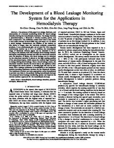
Figure 1 (a) 256X32b multi-poned dyilamic register file. (b) Leakage-sensitive and performance-critical 16-wide LBL and 8-wide GBL circuits.
-B
Injected Noire (low to high)
L=Naisc-induced hign 10 low
r=Noise-induced low high 10
Fiiure 2 Worst-case noise conditions for-16-wide LBL techniques: (a) DVT, (h) LBSF and (c) SFN.
2.5
4 2.0
:E: 1.5
-6
I
B
1.0
0.5
0.05
'."DC noise0.15 0.20 robustness
(a)
0'25
[unitygainDC naise1Vccl
Figure 4 LBSF domino mux for 8-wide GBL with worst-case noise conditions.
Delay improvement over DVT
LBSF
SFN
16%
14%
[unity gain DC noise I Vcc]
Figure 5 Delay vs. robustness for different GBL schemes.
*LBSF+DVT -
0.15
0.10
DC noise robustness
reduction
Figure 8 Delay, energy and total transistor width improvements over the best DVT design.
0
0.6
1.4
5 I
g 0.6
0.8
1.0 1.2 1.4 Delay [normabledl
16
Figure 6 Energy and total transistor width vs. delay for register file designs with DVT and LBSF LBL and GBL schemes.
6 1.2 I1.0
.0.4
0.6
nx
1.0 12 1.4 Delay [normalizedl
6
0.4
8
+SFN+LBSF
0.2
O F u l l LBSF
1.6
Figure 7 Energy and total transistor width vs. delay for register tile designs with DVT, SFN and LBSF LBL and GBL schemes.
1.0
2.0 3.0 4.0 SO Leakage Increase [XI
6.0
Figure 9 Delay vs. leakage increase for DVT, SFN and LBSF designs.
2002 Symposium On VLSl Circuits Digest of Technical Papers
321