A Linguistic Geometry for Space Applications D R A F T Boris Stilman Department of Computer Science & Engineering, University of Colorado at Denver, Campus Box 109, Denver, CO 80217-3364, USA. Tel. (303) 556-3614, Fax: (303) 556-8369, Email:
[email protected] Abstract: We develop a formal theory, the so-called Linguistic Geometry, in order to discover the inner properties of human expert heuristics, which were successful in a certain class of complex control systems, and apply them to different systems. This research relies on the formalization of search heuristics of high-skilled human experts, which allow to decompose complex system into the hierarchy of subsystems, and thus solve intractable problems reducing the search. The hierarchy of subsystems is represented as a hierarchy of formal attribute languages. This paper includes a formal survey of the Linguistic Geometry, and new example of a solution of optimization problem for the space robotic vehicles. This example includes actual generation of the hierarchy of languages, some details of trajectory generation and demonstrates the drastic reduction of search in comparison with conventional search algorithms. There are many real-world problems where human expert skills in reasoning about complex systems are incomparably higher than the level of modern computing systems. At the same time there are even more areas where advances are required but human problem-solving skills can not be directly applied. For example, there are problems of planning and automatic control of autonomous agents such as space vehicles, stations and robots with cooperative and opposing interests functioning in a complex, hazardous environment. Reasoning about such complex systems should be done automatically, in a timely manner, and often in a real time. Moreover, there are no highly-skilled human experts in these fields ready to substitute for robots (on a virtual model) or transfer their knowledge to them. There is no grand-master in robot control, although, of course, the knowledge of existing experts in this field should not be neglected – it is even more valuable. It is very important to study human expert reasoning about similar complex systems in the areas where the results are successful, in order to discover the keys to success, and then apply and adopt these keys to the new, as yet, unsolved problems. The question then is what
language tools do we have for the adequate representation of human expert skills? An application of such language to the area of successful results achieved by the human expert should yield a formal, domain independent knowledge ready to be transferred to different areas. Neither natural nor programming languages satisfy our goal. The first are informal and ambiguous, while the second are usually detailed, lower-level tools. Actually, we have to learn how we can formally represent, generate, and investigate a mathematical model based on the abstract images extracted from the expert vision of the problem. There have been many attempts to find the optimal (suboptimal) operation for real-world complex systems. One of the basic ideas is to decrease the dimension of the real-world system following the approach of a human expert in a certain field, by breaking the system into smaller subsystems. These ideas have been implemented for many problems with varying degrees of success [1, 2, 15]. Implementations based on the formal theories of linear and nonlinear planning meet hard efficiency problems [4, 12, 17, 22, 25]. An efficient planner requires an intensive use of heuristic knowledge. On the other hand, a pure heuristic implementation is unique. There is no general constructive approach to such implementations. Each new problem must be carefully studied and previous experience usually can not be applied. Basically, we can not answer the question: what are the formal properties of human heuristics which drove us to a successful hierarchy of subsystems for a given problem and how can we apply the same ideas in a different problem domain? In the 1960’s a formal syntactic approach to the investigation of properties of natural language resulted in the fast development of a theory of formal languages by Chomsky [5], Ginsburg [10], and others. This development provided an interesting opportunity for dissemination of this approach to different areas. In particular, there came an idea of analogous linguistic
representation of images. This idea was successfully developed into syntactic methods of pattern recognition by Fu [8], Narasimhan [16], and Pavlidis [18], and picture description languages by Shaw [23], Feder [6], Rosenfeld [20]. Searching for the adequate mathematical tools formalizing human heuristics of dynamic hierarchy, we have transformed the idea of linguistic representation of complex real-world and artificial images into the idea of similar representation of complex hierarchical systems [27]. However, the appropriate languages should possess more sophisticated attributes than languages usually used for pattern description. The origin of such languages can be traced back to the research on programmed attribute grammars by Knuth [11], Rozenkrantz [21], Volchenkov [36]. A mathematical environment (a “glue”) for the formal implementation of this approach was developed following the theories of formal problem solving and planning by Nilsson [17], Fikes [7], Sacerdoti [22], McCarthy, Hayes [13, 14], and others based on first order predicate calculus. To show the power of the linguistic approach it is important that the chosen model of the heuristic hierarchical system be sufficiently complex, poorly formalized, and have successful applications in different areas. Such a model was developed by Botvinnik, Stilman, and others, and successfully applied to scheduling, planning, and computer chess [2]. In order to discover the inner properties of human expert heuristics, which were successful in a certain class of complex control systems, we develop a formal theory, the so-called Linguistic Geometry [28-35]. This research includes the development of syntactic tools for knowledge representation and reasoning about large-scale hierarchical complex systems. It relies on the formalization of search heuristics, which allow one to decompose complex system into a hierarchy of subsystems, and thus solve intractable problems, reducing the search. These hierarchical images were extracted from the expert vision of the problem. The hierarchy of subsystems is represented as a hierarchy of formal attribute languages [28, 33].
1 Complex System A Complex System is the following eighttuple: < X, P, R p, { O N } , v , S i , S t, TR>, where X ={x i} is a finite set of points; P={p i} is a finite set of elements; P is a union of two nonintersecting subsets P1 and P2; Rp( x , y) is a set of binary relations of reachability in X (x and y are from X, p from P); ON(p)=x, where ON is a partial function of placement from P into X; v is a function on P with positive integer values; it describes the values of elements. The Complex System searches the state space, which should have initial and target states; Si and S t are the descriptions of the initial and target states in the language of the first order predicate calculus, which matches with each relation a certain WellFormed Formula (WFF). Thus, each state from Si or St is described by a certain set of WFF of the form {ON(pj)=xk}; TR is a set of operators, TRANSITION(p, x, y), of transition of the System from one state to another one. These operators describe the transition in terms of two lists of WFF (to be removed and added to the description of the state), and of WFF of applicability of the transition. Here, Remove list: ON(p)=x, ON(q)=y; Add list: ON(p)=y; Applicability list: (ON(p)=x)^Rp(x, y), where p belongs to P1 and q belongs to P2 or vice versa. The transitions are carried out in turn with participation of elements p from P1 and P2 respectively; omission of a turn is permitted. According to definition of the set P, the elements of the System are divided into two subsets P1 and P2. They might be considered as units moving along the reachable points. Element p can move from point x to point y if these points are reachable, i.e., Rp(x, y) holds. The current location of each element is described by the equation ON(p)=x. Thus, the description of each state of the System {ON(pj)=xk} is the set of descriptions of the locations of the elements. The operator TRANSITION(p, x, y) describes the change of the state of the System caused by the move of the element p from point x to point y. The element q from point y must be withdrawn (eliminated) if p and q belong to the different subsets P 1 and P2. The problem of the optimal operation of the System is considered as a search for the optimal
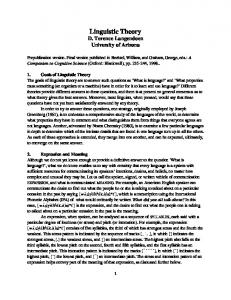
sequence of transitions leading from one of the initial states of Si to a target state S of St. It is easy to show formally that robotic system can be considered as the Complex System (see below). Many different technical and human society systems (including military battlefield systems, systems of economic competition, positional games) which can be represented as twin-sets of movable units (of two or more opposite sides) and their locations, thus, can be considered as Complex Systems. With such a problem statement for the search of the optimal sequence of transitions leading to the target state, we could use formal methods like those in the problem-solving system STRIPS [7], nonlinear planner NOAH [22], or in subsequent planning systems. However, the search would have to be made in a space of a huge dimension (for nontrivial examples). Thus, in practice no solution would be obtained. We devote ourselves to the search for an approximate solution of a reformulated problem. 2 Measurement of distances To create and study a hierarchy of dynamic subsystems we have to investigate geometrical properties of the Complex System. A map of the set X relative to the point x and element p for the Complex System is the mapping: MAP x,p : X —> Z+ , (where x is from X, p is from P), which is constructed as follows. We consider a family of reachability areas from the point x, i.e., a finite set of the following nonempty subsets of X {Mk x,p } (Fig.1):
x M4 x,p
M3 x,p
M2 x,p M1 x,p
X
Fig. 1. Interpretation of the family of reachability areas k=1: Mk x,p is a set of points m reachable in one step from x: Rp(x,m)=T;
k>1: Mk x,p is a set of points reachable in k steps and not reachable in k-1 steps, i.e., points m reachable from points of Mk-1x,p and not included in any Mix,p with numbers i less than k. Let MAPx,p (y)=k, for y from Mk x,p (number of steps from x to y). In the remainder points let MAPx,p (y)=2n, if y≠x (n is the number of points in X); MAPx,p (y)=0, if y=x. It is easy to verify that the map of the set X for the specified element p from P defines an asymmetric distance function on X: 1. MAPx,p (y) > 0 for x≠y; MAPx,p (x)=0; 2. MAPx,p (y)+MAPy,p (z) ≥ MAPx,p (z). If Rp is a symmetric relation, 3. MAPx,p (y)=MAPy,p (x). In this case each of the elements p from P specifies on X its own metric. Various examples of measurement of distances for robotic vehicles are considered later. 3 Language of Trajectories This language is a formal description of the set of lowest-level subsystems, the set of different paths between points of the Complex System. An element might follow a path to achieve the goal “connected with the ending point” of this path. A trajectory for an element p of P with the beginning at x of X and the end at the y of X (x ≠ y) with a length l is a following string of symbols with parameters, points of X: to=a(x)a(x1)…a(xl), where xl = y, each successive point xi+1 is reachable from the previous point xi, i.e., Rp(xi, xi+1) holds for i = 0, 1,…, l–1; element p stands at the point x: ON(p)=x. We denote tp(x, y, l) the set of trajectories in which p, x, y, and l coincide. P(to)={x, x1, ..., xl} is the set of parameter values of the trajectory to. A shortest trajectory t of tp(x, y, l) is the trajectory of minimum length for the given beginning x, end y and element p. Properties of the Complex System permit to define (in general form) and study formal grammars for generating the shortest trajectories. A general grammar (Table I) and its application to
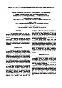
generating the shortest trajectory for a robotic vehicle will be presented later. Reasoning informally, an analogy can be set up: the shortest trajectory is analogous with a straight line segment connecting two points in a plane. An analogy to a k-element segmented line connecting these points is called an admissible trajectory of degree k, i.e., the trajectory which can be divided into k shortest trajectories. The admissible trajectories of degree 2 play a special role in many problems. As a rule, elements of the System should move along the shortest paths. In case of an obstacle, the element should move around this obstacle by tracing an intermediate point aside and going to and from this point to the end along the shortest trajectories. Thus, in this case, an element should move along an admissible trajectory of degree 2. A Language of Trajectories LtH(S) for the Complex System in a state S is the set of all the shortest and admissible (degree 2) trajectories of the length less than H. Different properties of this language and generating grammars were investigated in [32]. 4 Languages of Trajectory Networks After defining the Language of Trajectories, we have new tools for the breakdown of our System into subsystems. According to the ideas presented in [2], these subsystems should be various types of trajectory networks, i.e., the sets of interconnected trajectories with one singled out trajectory called the main trajectory. An example of such network is shown in Fig. 2. The basic idea behind these networks is as follows. Element po should move along the main trajectory a(1)a(2)a(3)a(4)a(5) to reach the ending point 5 and remove the target q4 (an opposite element). Naturally, the opposite elements should try to disturb those motions by controlling the intermediate points of the main trajectory. They should come closer to these points (to the point 4 in Fig. 2) and remove element po after its arrival (at point 4). For this purpose, elements q3 or q2 should move along the trajectories a(6)a(7)a(4) and a(8)a(9)a(4), respectively, and wait (if necessary) on the next to last point (7 or 9) for the arrival of element po at point 4. Similarly, element p1 of the same side as po might try to disturb the motion of q2 by controlling point 9 along the trajectory a(13)a(9). It makes sense for
the opposite side to include the trajectory a(11)a(12)a(9) of element q1 to prevent this control. q
q
3
4
q2
6 5
7
9 4 3
8
p
p2
1
13
12
10 q1
2
11
p0 1
Fig. 2. A network language interpretation. Similar networks are used for the breakdown of complex systems in different areas. Let us consider a linguistic formalization of such networks. The Language of Trajectories describes "one-dimensional" objects by joining symbols into a string employing reachability relation Rp(x, y). To describe networks, i.e., “multidimensional" objects made up of trajectories, we use the relation of trajectory connection. A trajectory connection of the trajectories t1 and t2 is the relation C(t1,t 2). It holds, if the ending link of the trajectory t 1 coincides with an intermediate link of the trajectory t2; more precisely t1 is connected with t2, if among the parameter values P(t2)={y,y1,…,y l} of trajectory t2 there is a value yi = xk, where t1=a(xo)a(x1)…a(xk). If t1 belongs to a set of trajectories with the common end-point, then the entire set is said to be connected with the trajectory t2. For example, in Fig. 2 the trajectories a(6)a(7)a(4) and a(8)a(9)a(4) are connected with the main trajectory a(1)a(2)a(3)a(4)a(5) through point 4. Trajectories a(13)a(9) and a(11)a(12)a(9) are connected with a(8)a(9)a(4). To formalize the trajectory networks we define and use routine operations on the set of trajectories: CAk(t1,t 2), a k-th degree of connection, and CA+(t1,t 2), a transitive closure.
Trajectory a(11)a(12)a(9) in Fig. 2 is connected degree 2 with trajectory a(1)a(2)a(3)a(4)a(5), i.e., C2(a(11)a(12)a(9), a(1)a(2)a(3)a(4)a(5)) holds. Trajectory a(10)a(12) in Fig. 2 is in transitive closure to the trajectory a(1)a(2)a(3)a(4)a(5) because C3(a(10)a(12), a(1)a(2)a(3)a(4)a(5)) holds by means of the chain of trajectories a(11)a(12)a(9) and a(8)a(9)a(4). A trajectory network W relative to trajectory to is a finite set of trajectories to,t 1,…,t k from the language LtH(S) that possesses the following property: for every trajectory ti from W (i = 1, 2,…,k) the relation CW+(ti,t o) holds, i.e., each trajectory of the network W is connected with the trajectory to that was singled out by a subset of interconnected trajectories of this network. If the relation CWm(ti, to) holds, trajectory ti is called the m negation trajectory. Obviously, the trajectories in Fig. 2 form a trajectory network relative to the main trajectory a(1)a(2)a(3)a(4)a(5). We are now ready to define network languages. A family of trajectory network languages LC(S) in a state S of the Complex System is the family of languages that contains strings of the form t(t1, param)t(t2, param)…t(tm, param), where param in parentheses substitute for the other parameters of a particular language. All the symbols of the string t 1, t2,…, tm correspond to trajectories that form a trajectory network W relative to t1. Different members of this family correspond to different types of trajectory network languages, which describe particular subsystems for solving search problems. One of such languages is the language that describes specific networks called Zones. They play the main role in the model considered here [2, 26, 33, 34]. A formal definition of this language is essentially constructive and requires showing explicitly a method for generating this language, i.e., a certain formal grammar, which is presented in the [33, 34]. In order to make our points transparent, here, we define the Language of Zones informally. A Language of Zones is a trajectory network
language with strings of the form Z=t(po,t o,τo) t(p1,t 1,τ1)…t(pk,t k,τk), where to,t 1,…,t k are the trajectories of elements po,p 2,…,p k respectively; τo,τ1,…,τk are positive integer numbers (or 0) which “denote the time allotted for the motion along the trajectories” in a correspondence to the mutual goal of this Zone: to remove the target element – for one side, and to protect it – for the opposite side. Trajectory t(po,t o,τo) is called the main trajectory of the Zone. The element q standing on the ending point of the main trajectory is called the target. The elements po and q belong to the opposite sides. To make it clearer let us show the Zone corresponding to the trajectory network in Fig. 2. Z=t(po,a(1)a(2)a(3)a(4)a(5), 4) t(q3,a(6)a(7)a(4), 3) t(q2, a(8)a(9)a(4), 3)t(p1, a(13)a(9), 1) t(q1, a(11)a(12)a(9), 2) t(p2, a(10)a(12), 1) Assume that the goal of the white side is to remove target q4, while the goal of the black side is to protect it. According to these goals element po starts the motion to the target, while blacks start in its turn to move their elements q2 or q3 to intercept element po. Actually, only those black trajectories are to be included into the Zone where the motion of the element makes sense, i. e., the length of the trajectory is less than the amount of time (third parameter τ) allocated to it. For example, the motion along the trajectories a(6)a(7)a(4) and a(8)a(9)a(4) makes sense, because they are of length 2 and time allocated equals 3: each of the elements has 3 time intervals to reach point 4 to intercept element po assuming one would go along the main trajectory without move omission. According to definition of Zone the trajectories of white elements (except po) could only be of the length 1, e.g., a(13)a(9) or a(10)a(12). As far as element p1 can intercept motion of the element q2 at the point 9, blacks include into the Zone the trajectory a(11)a(12)a(9) of the element q1, which has enough time for motion to prevent this interception. The total amount of time allocated to the whole bunch of black trajectories connected (directly or indirectly) with the given point of main trajectory is determined by the number of that point. For example, for the point 4 it equals 3 time intervals.
A language LZ(S) generated by the certain grammar G Z [33, 34] in a state S of a Complex System is called the Language of Zones. Network languages allow us to describe the "statics", i.e., the states of the System. We proceed with the description of the "dynamics" of the System, i.e., the transitions from one state to another. The transitions describe the change of the descriptions of states as the change of sets of WFF. After each transition a new hierarchy of languages should be generated. Of course, it is an inefficient procedure. To improve an efficiency of applications in a process of the search it is important to describe the change of the hierarchy of languages. A study of this change should help us in modifying the hierarchy instead of regenerating it in each state. The change may be described as a hierarchy of mappings – translations of languages. Each language should be transformed by the specific mapping called a translation. Translations of Languages of Trajectories and Zones are considered in [34].
specified points. On the other hand S t can specify states where opposing robots of the highest value are destroyed. The set of WFF {ON(pj) = xk} corresponds to the list of robots with their coordinates in each state. TRANSITION(p, x, y) represents the move of the robot p from the location x to location y; if a robot of the opposing side stands on y, a removal occurs, i.e., robot on y is destroyed and removed.
z 8 7 6 5 4 y
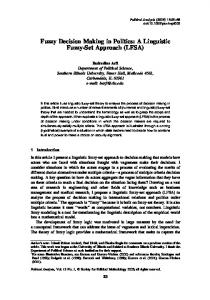
5 Complex System of Space Robotic Vehicles The robotic model can be represented as a Complex System naturally (Fig. 3). A set of X represents the operational district which could be the area of combat operation broken into smaller cubic areas, “points”, e.g., in the form of the big cube of 8 x 8 x 8, n = 512. It could be a space operation, where X represents the set of different orbits, or an air force battlefield, etc. P is the set of robots or autonomous vehicles. It is broken into two subsets P1 and P2 with opposing interests; Rp( x , y ) represent moving capabilities of different robots for different problem domains: robot p can move from point x to point y if Rp(x, y) holds. Some of the robots can crawl, the other can jump or ride, sail and fly, or even move from one orbit to another. Some of them move fast and can reach point y (from x) in “one step”, i.e., Rp(x, y) holds, others can do that in k steps only, and many of them can not reach this point at all. ON(p)=x, if robot p is at the point x; v(p) is the value of robot p. This value might be determined by the technical parameters of the robot. It might include the immediate value of this robot for the given combat operation; Si is an arbitrary initial state of operation for analysis, or the starting state; S t is the set of target states. These might be the states where robots of each side reached
3
x
8 2 8 7 67 6 5 5 4 3 1 34 2 1 1 2 Fig. 3. A problem for autonomous space robotic vehicles.
Space robotic vehicles with different moving capabilities are shown in Fig. 3. The operational district X is the cubic table of 8 x 8 x 8. Robot WINTERCEPTOR (White Interceptor) located at 118 (x=1, y=1, z=8), can move to any next location, i.e., 117, 217, 218, 228, 227, 128, 127. The other robotic vehicle B-STATION (double-ring shape in Fig. 3) from 416 can move only straight ahead towards the goal area 816 (shaded in Fig. 3), one square at a time, e.g., from 416 to 516, from 516 to 616, etc. Robot BINTERCEPTOR (Black Interceptor) located at 186, can move to any next square similarly to robot W-INTERCEPTOR. Robotic vehicle WSTATION located at 266 is analogous with the robotic B-STATION; it can move only straight ahead to the goal area 268 (shaded in Fig. 3). Thus, robot W-INTERCEPTOR on 118 can reach any of the points y ∈{117, 217, 218, 228, 227, 128, 127} in one step, i.e., RWINTERCEPTOR(118, y) holds, while WSTATION can reach only 267 in one step.
Assume that robots W-INTERCEPTOR and WSTATION belong to one side, while BINTERCEPTOR and B-STATION belong to the opposite side: W-INTERCEPTOR ∈ P1, WSTATION ∈ P1, B-INTERCEPTOR ∈ P2, BSTATION ∈ P2. Also assume that both goal areas, 816 and 268, are the safe areas for BSTATION and W-STATION, respectively, if station reached the area and stayed there for more than one time interval. Each of the STATIONs has powerful weapons capable to destroy opposing INTERCEPTORs at the next diagonal locations ahead of the course. For example WSTATION from 266 can destroy opposing INTERCEPTORs at 157, 257, 357, 367, 377, 277, 177, 167. Each of the INTERCEPTORs is capable to destroy an opposing STATION approaching its location from any direction, but it also capable to protect its friendly STATION approaching its prospective location. In the latter case the joint protective power of the combined weapons of the friendly STATION and INTERCEPTOR (from any next to the STATION area) can protect the STATION from interception. For example, W-INTERCEPTOR located at 156 can protect W-STATION on 266 and 267. The battlefield considered can be broken into two local operations. The first operation is as follows: robot B-STATION should reach the strategic point 816 safely and stay there for at list one time interval, while W-INTERCEPTOR will try to intercept this motion. The second operation is similar: robot W-STATION should reach point 268, while B-INTERCEPTOR will try to intercept this motion. After reaching the designated strategic area the (attacking) side is considered as a winner of the local operation and the global battle. The only chance for the opposing side to revenge itself is to reach its own strategic area within the next time interval and this way end the battle in a draw. The conditions considered above give us St, the description of target states of the Complex System. The description of the initial state Si is obvious and follows from Fig. 3. Assume also that due to the shortage of resources (which is typical in real combat operation) or some other reasons, each side can not participate in both operations simultaneously. It means that during the current time interval, in case of White turn, either W-STATION or W-
INTERCEPTOR can move. Analogous condition holds for Black. Of course, it does not mean that if one side began participating in one of the operations it must complete it. Any time on its turn each side can switch from one operation to another, e.g., transferring resources (fuel, weapons, human resources, etc.), and later switch back. It seems that local operations are independent, because they are located far from each other. Moreover, the operation of B-STATION from 418 looks like unconditionally winning operation, and, consequently, the global battle can be easily won by the Black side. Is there a strategy for the White side to make a draw? Of course, this question can be answered by the direct search employing, for example, minimax algorithm with alpha-beta cut-offs. Experiments with the computer chess programs showed that for the similar 2-D problem (in chess terms – the R.Reti endgame) the search tree includes about a million moves (transitions). Of course, in the 3-D case the search would require billions of moves. It is very interesting to observe the drastic reduction of search employing the Linguistic Geometry tools. In order to demonstrate generation of the Hierarchy of Languages for this problem, below we consider generation of the Language of Trajectories for the robotic system on example of generation of the shortest trajectory from point 336 to point 816 for the robot WINTERCEPTOR (Fig. 4, see also Fig. 16). (Point 336 is the location of W-INTERCEPTOR in one of the states of the System in the process of the search.) y 8 7 6 5 4 3 2 1
x
1 2 3 4 5 6 7 8 Fig. 4. Interpretation of Zone for the Robotic System (projection to xy-plane).
Table I. A grammar of shortest trajectories G t(1) L Q Kernel, π k FT FF 1 Q1 S (x,y,l) –>A(x, y, l) two ø 2i Q2 A(x,y,l)–> a(x)A(next i (x,l),y,f(l)) two 3 3
Q3 A(x, y, l) –>a(y)
ø
ø
V T ={a} is the alphabet of terminal symbols, V N ={S , A} is the alphabet of nonterminal symbols, V PR =TruthUPredUConUVarUFuncU{symbols of logical operations} is the alphabet of the first order predicate calculus PR, Truth={T, F} Pred ={Q1 ,Q2 ,Q3 } are predicate symbols: Q1 (x, y, l) = (MAPx,p (y)=l) (0Var, a –>{x}, is such a mapping that matches each symbol of the alphabet V T UV N a set of formal parameters; L= {1,3} U two, two={2 1,2 2,...,2 n} is a finite set called the set of labels; labels of different productions are different; Qi are the WFF of the predicate calculus PR, the conditions of applicability of productions; FT is a subset of L of labels of the productions permitted on the next step derivation if Q=T; it is called a permissible set; FF is analogous to FT but these productions are permitted in case of Q=F. At the beginning of derivation: x=xo, y=yo, l=lo, x o ∈ X, yo ∈ X, lo ∈ Z+ , p ∈ P. next i is defined as follows: D(nexti)= X x Z+ x X2 x Z+ x P (This is the domain of function next.) SUM={v |v ∈ X, MAPxo,p (v)+MAPyo,p (v)=lo}
STk(x)={v | v from X, MAPx,p (v)=k}, MOVEl(x) is an intersection of the following sets: ST1(x), STlo-l+1(xo) and SUM. If MOVEl(x)={m1, m2, ...,mr}≠ Ø then nexti(x, l)=mi for i≤r ; nexti(x, l)=mr for r means application of the production with the label l): S (33, 81, 5)1=>A(33, 81, 5) 21=>a(33)A(next1(33, 5), 81, 5)
5 54 5 5 5 4 5 4 5 54 4 3 32 3 43 4 5 4 5 5 5 3 4 5 4 3 5 54 4 3 3 2 252 2 22 2 2 3 3 4 5 3 22 2 2 2 2 22 3 4 5 4 3 2 2 2 22 2 2 2 2 2 4 5 2 2 2 2 5 4 23 5 2 2 22 3 2 2 2 2 2 5 4 34 2 2 2 3 2 2 2 2 45 2 2 2 5 4 3 2 2 2 22 5 3 2 2 4 2 2 3 5 4 2 2 2 3 2 2 2 22 45 2 2 5 4 2 2 2 2 2 33 5 3 3 3 3 3 3 5 4 44 x 3 3 33 44 4 4 5 y 5 4 5 4 4 4 4 55 8 5 5 4 4 5 5 5 8 7 5 67 5 6 5 5 5 55 4 5 4 3 3 2 1 12
Fig. 5. MAP336, INTERCEPTOR Thus we have to compute MOVE (see definition of the function nexti from the grammar G t(1)). First we have to determine the set of SUM, that is, we need to know values of MAP33,W-INTERCEPTOR and MAP81,W-INTERCEPTOR (shown in Fig. 6) on X. 5
5 5
5
7
7
7
7
7
7
7
7
4
4 3 4 2 3 4 2 3 4 2 3 4
5 5 5
7
6
6
6
6
6
6
6
7 6 5 5 5 5 5 5 7 6 5 4 4 4 4 4
5 5
7 7
6 6
5 5
4 4
3 3
3 2
3 2
3 2
2 3 4 2 3 4
5
7 7
6 6
5 5
4 4
3 3
2 2
1 1
1 0
5
4
5 5 4 4
3
3 3
3 3
4 4
2 2 2 2 1 1
2 1
2 1 2 1 2 2
2
0 1 1 1 2
5
5
F i g . 6 . MAP33,W-INTERCEPTOR (left) and MAP81,W-INTERCEPTOR (right) Adding these tables as matrices we compute SUM ={v | v ∈ X, MAP33, W-INTERCEPTOR(v) + MAP81,WINTERCEPTOR(v) = 5} (Fig. 7). For the general 3-D case we should add 3-D matrices like those shown in Fig. 5. The next step is the computation of ST1(33)= {v |v from X,MAP33,W-INTERCEPTOR(v)=1} which is shown in Fig. 8. In order to complete computation of the set MOVE5(33) we have to
determine the following intersection: ST1(33), ST5-5+1(33)=ST1(33) and SUM.
5
5 5
5 5 5
5
5 5
5 5 5 5
Fig. 7. SUM.
5
Fig. 8. ST1(33).
Consequently, MOVE 5(33)={44, 43, 42}; and next1(33, 5)=44, next2(33, 5)=43, next3(33, 5)=42. Since the number of different values of next is equal to 3 (here r=3, see definition of the function next, Table I) we could branch at this step, apply productions 21, 22 and 23 simultaneously, and continue both derivations independently. This could be accomplished in a parallel computing environment. Let us proceed with the first derivation. a(33)A(44, 81,4) 21=>a(33)a(44) A(next1(44, 4), 81, 3) We have to compute next1(44, 4) and, as on the preceding step, have to determine MOVE4(44). To do this we have to compute ST1(44)={v | v ∈ X, MAP44,W-INTERCEPTOR(v)=1},(Fig. 9) ST5-4+1(33) = ST2(33) = {v |v ∈ X, MAP33,W-INTERCEPTOR(v)=2}, (Fig. 10). The set of SUM is the same on all steps of the derivation. Hence, MOVE4(44) is the intersection of the sets shown in Fig. 7, 9, 10; MOVE4(44)= {54, 53, 52}; and next1(44, 4) = 54; next2(44, 4) = 53, next3(44, 4) = 52. Thus, the number of different values of the function next is equal to 3 (r=3), so the number of continuations of derivation should be multiplied by 3.
Fig. 9. ST1(44)
Fig. 10. ST2(33).
Let us proceed with the first one: a(33)a(44)A(54, 81, 3) 21=> ... Eventually, we will generate one of the shortest trajectories for the robot W-INTERCEPTOR from 33 to 81: a(33)a(44)a(54)a(63)a(72)a(81). Similar generating techniques are used to generate higher level subsystems, the networks of paths, i.e., the Language of Zones. For example,, incomplete Zones shown in Fig. 4 is as follows (in 2-D coordinates): t(B-STATION,tB,5)t(W-INTERCEPTOR,tF,5), where tB=a(41)a(51)a(61)a(71)a(81), tF= a(33)a(44)a(54)a(63)a(72)a(81). The details of generation of different Zones are considered in [33, 34]. 6 Search Generation for Space Robotic System Consider how the hierarchy of languages works for the optimal control of the space robotic system introduced above (Fig. 3). We generate the search of the Language of Translations representing it as a conventional search tree (Fig. 12) and comment on its generation. In fact, this tree is close to the search tree of the relative 2-D problem [35]. Moreover, it is close to the search tree of the R.Reti endgame generated by program PIONEER in 1977 and presented at the World Computer Chess Championship (joint event with IFIP Congress 77, Toronto, Canada). Later it was published in different journals and books, in particular in [2]. First, the Language of Zones in the start state is generated. The targets for attack are determined within the limited number of steps which is called a horizon. In general, the value of the horizon is unknown. As a rule, this value can be determined from the experience of solving specific classes of problems employing Linguistic Geometry tools. In absence of such experience, first we have to consider the value of 1 as a horizon, and solve the problem within this value. If we still have resources available, i.e., computer time, memory, etc., we can increase the horizon by one. After each increase we have to regenerate the entire model. This increase means a new level of “vigilance” of the model, and, consequently, new greater need for resources. In our case it is easy to show that within the horizons of 1, 2, 3, 4 all the models are “blind” and corresponding searches do not give a
“reasonable” solution. But, again, after application of each of the consecutive values of the horizon we will have a solution which can be considered as an approximate solution within the available resources. Thus, let the horizon H of the language LZ(S) is equal to 5, i.e., the length of main trajectories of all Zones must not exceed 5 steps. All the Zones generated in the start state are shown in Fig. 11. y 8 7 6 5 4 3 2 1
x 1 2
3 4
5
6 7
8 z
8 7 6 5 4 3 2 1
y 8 z
7 6
5 4
3 2 1
8 7 6 5 4 3 2 1
x 1 2 3 4 5 6 7 8 Fig. 11. Interpretation of Zones in the initial state of the space robotic system (3 projections).
267-268 277:268 266-267 186-277 118-227 277:267 118-228 277:267 186-277 266:277
-1 -1 -1
1
266-267 276:267 276:266 186-276
-1 0 266-267
276:267
227-336 416-516 336-346 276:266 336-445 276:266 118-227 516-616 276-277 276-277 266:277
-1 -1 0 0 0
1
267-268 277:268
-1
416-516 266-267 186-277 227-336 277:267
-1
227-337 277:267
-1
186-277 266:277 1 227-336 186-276 266-267 276:267 336-346 276:266 336-445 276:266 516-616
0
-1 -1 0
516-616 445-356 0 276-277 266:277
186-275 266-267 416-516 267-268
1
1
Fig. 12. Search tree for the optimization problem for space robotic vehicles.
Zones for INTERCEPTORSs as attacking elements are shown in the top diagram, while Zones for STATIONs – in the bottom one. For example, one of the Zones for W-STATION, ZWS is as follows: ZWS=t(W-STATION, a(266)a(267)a(268), 3) t(B-INTERCEPTOR, a(186)a(277)a(268), 3) t(B-INTERCEPTOR,a(186)a(276)a(267), 2) t(W-STATION, a(266)a(277), 1) The other trajectories of B-INTERCEPTOR, e.g., the second trajectory, a(186)a(177)a(268), leading to the point 268 is included into different Zone; for each Zone only one trajectory from each bundle of trajectories with the same beginning and end is taken.
value is given by the special procedure of “generalized square rules” built into the grammar. y 8 7 6 5 4 3 2 1
x 1 2
Generation begins with the move 1. 266-267 in the “white” Zone with the target of the highest value and the shortest main trajectory. The order of consideration of Zones and particular trajectories is determined by the grammar of translations. The computation of move-ordering constraints is the most sophisticated procedure in this grammar. It takes into account different parameters of Zones, trajectories, and the socalled chains of trajectories.
3 4
5
6 7
8 z
8 7 6 5 4 3 2 1
y 8 z
z 8 7 6 5 4 y
3
x
8 2 8 7 67 6 5 5 4 3 1 34 2 1 1 2 Fig. 1 3 . The state where control Zone from 118 to 268 was detected.
Next move, 1. ... 186-277, is in the same Zone along the first negation trajectory. The interception continues: 2. 267-268 277:268 (Fig. 13). Symbol “:” means the removal of element. Here the grammar terminates this branch with the value of -1 (as a win of the Black side). This
7 6
5 4
3 2 1
8 7 6 5 4 3 2 1
x 1 2 3 4 5 6 7 8 Fig. 14. Interpretation of Zones in the state where control Zone from 118 to 268 was included first (3 projections). Then, the grammar initiates the backtracking climb. Each backtracking move is followed by the inspection procedure, the analysis of the subtree generated in the process of the earlier search. After climb up to the move 1. ... 186-277, the
tree to be analyzed consists of one branch (of two plies): 2. 267-268 277-268. The inspection procedure determined that the current minimax value (-1) can be “improved” by the improvement of the exchange in the area 268 (in favor of the White side). This can be achieved by participation of W-INTERCEPTOR from 118, i.e., by generation and inclusion of the new so-called “control” Zone with the main trajectory from 118 to 268. The set of different Zones from 118 to 268 (the bundle of Zones) is shown in Fig. 14. The move-ordering procedure picks the subset of Zones with main trajectories passing 227. These trajectories partly coincide with the main trajectory of another Zone attacking the opposing BSTATION on 516. The motion along such trajectories allows to “gain the time”, i.e., to approach two goals simultaneously. The generation continues: 2. 118-227 277-267. Again, the procedure of “square rules” cuts the branch, evaluates it as a win of the black side, and the grammar initiates the climb. Move 2. 118-227 is changed for 2. 118-228. Analogously to the previous case, the inspection procedure determined that the current minimax value (-1) can be improved by the improvement of the exchange on 267. Again, this can be achieved by the inclusion of Zone from 118 to 267. Of course, the best “time-gaining” move in this Zone is 2. 118227, but it was already included (as move in the Zone from 118 to 268). The other untested move in the Zone from 118 to 267 is 2. 118-228. Obviously the grammar does not have knowledge that trajectories to 267 and 268 are “almost” the same. After the next cut and climb, the inspection procedure does not find new Zones to improve the current minimax value, and the climb continues up to the start state. The analysis of the subtree shows that inclusion of Zone from 118 to 268 in the start state can be useful: the minimax value can be improved. Similarly, the most promising “time-gaining” move is 1. 118-227. The Black side responded 1. ... 186-277 along the first negation trajectories a(186)a(277)a(267) and a(186)a(277)a(268) shown in Fig. 12 (better see yz-projection). Obviously, 2. 266:277, and the branch is terminated. The grammar initiates the climb and move 1. ... 186-277 is changed for 1. ... 186-276 along the trajectory a(186)a(276)a(266). Note, that grammar “knows” that in this state trajectory a(186)a(276)a(266) is active, i.e., B-
INTERCEPTOR has enough time for interception. The following moves are in the same Zone of W-STATION: 2. 266-267 276:267. This state is shown in Fig. 15. The “square rule procedure” cuts this branch and evaluates it as a win of the Black side.
z 8 7 6 5 4 y
3
x
8 2 8 7 67 6 5 5 4 3 1 34 2 1 1 2 Fig. 1 5 . The state where control Zone from 227 to 267 was detected.
New climb up to the move 2. ... 186-276 and execution of the inspection procedure result in the inclusion of the new control Zone from 227 to 267 in order to improve the exchange in the area 267. The set of Zones with different main trajectories from 227 to 267 is shown in Fig. 16. Besides that, the trajectories from 227 to 516, 616, 716, and 816 are shown in the same Fig. 16. These are “potential” first negation trajectories. It means that beginning with the second symbol a(336), a(337), a(338), or a(326), a(327), a(328), or a(316), a(317), a(318), these trajectories become first negation trajectories in the Zone of B-STATION h5. Speaking informally, from the areas listed above W-INTERCEPTOR can intercept B-STATION (in case of white move). The main trajectories of control Zones passing one of three points, 336, 337, or 338, partly coincide with the potential first negation trajectories. The motion along such trajectories allows to “gain the time”, i.e., to approach two goals simultaneously. The moveordering procedure picks the subset of Zones with the main trajectories passing 336. Thus, 2. 227336. This way proceeding with the search we will
generate the tree that consists of 56 moves. Obviously, this is a drastic reduction in comparison with a billion-move trees generated by conventional search procedures. y 8 7 6 5 4 3 2 1
x 1 2
3 4
5
6 7
8 z
8 7 6 5 4 3 2 1
y 8 z
7 6 5 4
3 2
1
8 7 6 5 4 3 2 1
x 1 2 3 4 5 6 7 8 Fig. 16. Interpretation of Zones in the state where control Zone from 227 to 267 was included first (3 projections). 7 Discussion The approach to understanding of dynamic hierarchical systems considered here will
encompass the discovery of geometrical properties of subsystems and details of interactions between the elements within subsystems and between different subsystems. We will understand the details of influence of this complex hierarchical structure on the reduction of the search for suboptimal operation. Most importantly, it should allow a better understanding of the evaluation and control of the solution quality. This contribution to the formalization and generalization of human search heuristics should allow for the expansion of advanced human heuristic methods discovered in different complex systems to other real-world systems where existing methods are not sufficient. The research will lead to the development of efficient applications to autonomous navigation in hazardous environment, robot control, combat operations planning as well as applications in different nonmilitary areas. The development of applications will be accomplished by the design of separate programs, and, later on, by the program implementation of the general hierarchy of formal grammars and applying it to a given problem. References 1. Albus, J. (1991) “Outline for a Theory of Intelligence”, IEEE Trans. on Systems, Man and Cybernetics, 3:473-509. 2. Botvinnik, M.M. (1984) Computers in Chess: Solving Inexact Search Problems. Springer Series in Symbolic Computation, Springer-Verlag, New York. 3. Botvinnik, M., Petriyev, E., Reznitskiy, A., et al. (1983) “Application of New Method for Solving Search Problems For Power Equipment Maintenance Scheduling”, Economics and Mathematical Methods, 6:1030-1041 (in Russian). 4. Chapman, D. (1987) “Planning for conjunctive goals”, Artificial Intelligence 32(3). 5. Chomsky, N. (1963) “Formal Properties of Grammars”, in Handbook of Mathematical Psychology, eds. R.Luce, R.Bush, E. Galanter., vol. 2, John Wiley & Sons, New York, pp. 323-418. 6. Feder, J. (1971) “Plex languages”, Information Sciences, 3: 225–241. 7. Fikes, R.E. and Nilsson, N.J. (1971) “STRIPS: A New Approach to the Application of Theorem Proving in Problem Solving”, Artificial Intelligence 2: 189–208. 8. Fu, K.S. (1982) Syntactic Pattern
9.
10. 11. 12. 13. 14.
15.
16. 17. 18. 19.
20. 21. 22. 23.
24. 25.
Recognition and Applications, Prentice Hall, Englewood Cliffs. Garey, M.R. and D.S.Johnson D.S. (1991) Computers and Intractability: A Guide to the Theory of NP-Completeness. W.H. Freeman and Co., San Francisco. Ginsburg, S. (1966) The Mathematical Theory of Context-Free Languages, McGraw Hill, New York. Knuth, D.E. (1968) “Semantics of ContextFree Languages”, Mathematical Systems Theory 2:127–146. McAllester, D. and Rosenblitt, D. (1991) Systematic Non-Linear Planning, Proc. of AAAI-91, pp. 634-639. McCarthy, J. (1980) “Circumscription–A Form of Non-Monotonic Reasoning”, Artificial Intelligence 13:27-39. McCarthy, J. and Hayes, P.J. (1969) “Some Philosophical Problems from the Standpoint of Artificial Intelligence”, Machine Intelligence 4:463–502. Mesarovich, M.D., Macko, D., and Takahara Y. (1970) Theory of Hierarchical Multilevel Systems., Academic Press, New York. Narasimhan, R.N. (1966) “Syntax–Directed Interpretation of Classes of Pictures”, Communications of the ACM 9: 166–173. Nilsson, N.J. (1980) Principles of Artificial Intelligence, Tioga Publ., Palo Alto, CA. Pavlidis, T. (1977) Structural Pattern Recognition, Springer-Verlag, New York. Reznitskiy, A.I. and Stilman, B. (1983) “Use of Method PIONEER in Automating the Planning of Maintenance of PowerGenerating Equipment,” Automatics and Remote Control, 11: 147-153, (in Russian). Rosenfeld, A. (1979) Picture Languages, Formal Models for Picture Recognition, Academic Press. Rozenkrantz, D.J. (1969) “Programmed Grammars and Classes of Formal Languages,” J. of the ACM, 1:107–131. Sacerdoti, E.D. (1975) “The Nonlinear Nature of Plans,” Proc. Int. Joint Conference on Artificial Intelligence. Shaw, A.C. (1969) “A Formal Picture Description Scheme as a Basis for Picture Processing System,” Information and Control 19: 9-52. Simon, H.A. (1980) The Sciences of the Artificial, 2-nd ed., The MIT Press, Cambridge, MA. Stefik, M. (1981) “Planning and meta-
26.
27.
28.
29.
30.
31.
32.
33.
34.
35.
36.
planning (MOLGEN: Part 2),”Artificial Intelligence, 2:141-169. Stilman, B. (1977) “The Computer Learns”, in Levy, D.,1976 US Computer Chess Championship, Computer Science Press, Woodland Hills, CA, 83-90. Stilman, B. (1985)“Hierarchy of Formal Grammars for Solving Search Problems,” in Artificial Intelligence. Results and Prospects, Proceedings of the International Workshop, Moscow, 63–72, (in Russian). Stilman, B. (1992) “A Linguistic Geometry of Complex Systems, Abstr. Second Int. Symposium on Artificial Intelligence and Mathematics,” Ft. Lauderdale, FL. The full paper was submitted to Annals of Math. & Artificial Intelligence. Stilman, B. (1992) “A Syntactic Structure for Complex Systems”, Proc. Second Golden West Int. Conf. on Intelligent Systems, Reno, NE, June, 269-274. Stilman, B. (1992) “A Geometry of Hierarchical Systems: Generating Techniques”, Proc. Ninth Israeli Conference on Artificial Intelligence and Computer Vision, pp. 95-109, Dec., Tel Aviv, Israel. Stilman, B. (1992) “A Syntactic Approach to Geometric Reasoning about Complex Systems,” Proc. Fifth Int. Symp. on Artificial Intelligence, Cancun, Mexico, Dec., 115-124. Stilman, B. (1993) “A Linguistic Approach to Geometric Reasoning,” Int. J. Computers and Mathematics with Applications, 26(7), 29-57. Stilman, B. (1993) “Network Languages for Complex Systems,” Int. J. Computers and Mathematics with Applications, 26(8), 5179. Stilman, B. (1994) “Translations of Network Languages,” Int. J. Computers and Mathematics with Applications, 27(2), 6598, (to appear). Stilman, B.(1994) “A Formal Model for Heuristic Search,” Proceedings of the 22nd Annual ACM Computer Science Conf., Phoenix, AZ, (to appear). Volchenkov, N.G. (1979) “The Interpreter of Context-Free Controlled Parameter Programmed Grammars,” in L.T. Kuzin, Eds., Cybernetics Problems. Intellectual Data Banks, The USSR Academy of Sci., Moscow, pp. 147–157, (in Russian).