top-down approach using the concept of abstraction. ... part of physical design and is not discussed here. analyzed ... straction concepts such as generalization.
A Logical Design Methodology for Relational Databases Using the Extended Entity-Relationship Model TOBY J. TEOREY Computing Research Laboratory, Electrical Ann Arbor, Michigan 48109-2122
Engineering
and Computer Science, The University
of Michigan,
DONGQING YANG Computer Science and Technology, Peking Uniuersity,
Beijing, The People’s Republic of China
JAMES P. FRY Computer and Information Systems, Graduate School of Business Administration, Ann Arbor, Michigan 48109-1234
The University
of Michigan,
A database design methodology is defined for the design of large relational databases. First, the data requirements are conceptualized using an extended entity-relationship model, with the extensions being additional semantics such as ternary relationships, optional relationships, and the generalization abstraction. The extended entityrelationship model is then decomposed according to a set of basic entity-relationship constructs, and these are transformed into candidate relations. A set of basic transformations has been developed for the three types of relations: entity relations, extended entity relations, and relationship relations. Candidate relations are further analyzed and modified to attain the highest degree of normalization desired. The methodology produces database designs that are not only accurate representations of reality, but flexible enough to accommodate future processing requirements. It also reduces the number of data dependencies that must be analyzed, using the extended ER model conceptualization, and maintains data integrity through normalization. This approach can be implemented manually or in a simple software package as long as a “good” solution is acceptable and absolute optimality is not required. Categories and Subject Descriptors: data models
H.2.1 [Database
Management]:
Logical Design-
General Terms: Databases, Design Additional Key Words and Phrases: Entity-relationship relational databases
INTRODUCTION
Relational database design has been accomplished with a variety of approaches, including the top-down, bottom-up, and combined methodologies. The traditional
model, integrity,
logical design,
approach has been a low-level bottom-up activity synthesizing data elements into normalized relations using the inter-dataelement dependencies resulting from the requirements analysis [Codd 1970, 1974; Martin 1982; Date 1984; Smith 19851.
Permission to copy without fee all or part of this material is granted provided that the copies are not made or distributed for direct commercial advantage, the ACM copyright notice and the title of the publication and its date appear, and notice is given that copying is by permission of the Association for Computing Machinery. To copy otherwise, or to republish, requires a fee and/or specific permission. 0 1986 ACM 0360-0300/86/0600-0197 $00.75
Computing
Surveys, Vol. 18, No. 2, June 1986
198
l
T. J. Teorey, D. Yang, and J. P. Fry
CONTENTS
INTRODUCTION 1. ER MODELING AND EXTENDED CONSTRUCTS 1.1 Original Classes of Objects (ER Model) 1.2 Extended Classes of Objects (EER Model) 1.3 Fundamental EER Constructs 2. EER MODELING OF REQUIREMENTS (STEP 1) 2.1 Design Step 1 Details 2.2 An Example Database: Cohpany Personnel and Projects 3. TRANSFORMATION OF THE EER MODEL TO RELATIONS (STEP 2) 3.1 Transformation Rules 3.2 Design Step 2 Details 3.3 Example 4. NORMALIZATION OF RELATIONS (STEP 3) 4.1 Design Step 3 Details 4.2 Example 5. REFINEMENTS TO THE LOGICAL DESIGN PROCESS 5.1 Addition of More Semantics to Conceptual Modeling 5.2 Relation Refinement for Usage Efficiency 6. CONCLUSION APPENDIX: SUMMARY OF LOGICAL RELATIONAL DATABASE DESIGN STEPS ACKNOWLEDGMENTS REFERENCES
Although the traditional process is vital to the design of relational databases, its complexity, particularly in large databases, can be overwhelming to the point where practical designers often do not bother to master it or even use it with any regularity. At the theoretical level a top-down approach has been investigated with regard to the universal relation assumption [Beeri et al. 1978; Kent 19811. In practice, typically a few basic relations are defined by the requirements analysis process, and then a combination of the top-down and bottomup approaches is used. The combined approach has recently become much more popular because of the introduction of a well-established conceptual design tool, the entity-relationship model, into this process [Date 1984; Sweet 1985; Yang et al. 19851. The entity-relationship (ER) model has been most successful as a tool for commuComputing
Surveys, Vol. 18, No. 2, June 1986
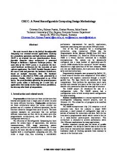
nication between the designer and the end user during the requirements analysis and conceptual design phases because of its ease of understanding and its convenience in representation [Chen 19761. One of the reasons for its effectiveness is that it is a top-down approach using the concept of abstraction. The number of entities (i.e., the objects that we want to collect information about) in a database is typically an order of magnitude less than the number of data elements. Therefore, using entities as an abstraction for data elements and focusing on the interentity relationships greatly reduces the number of objects under consideration and simplifies the analysis. Although it is still necessary to represent data elements by attributes of entities at the conceptual level, their dependencies are normally confined to the other attributes within the entity or, in some cases, to those attributes associated with other entities that have a direct relationship to their entity. The major interattribute dependencies are between the entity keys (unique identifiers) of different entities that are captured in the ER modeling process. Special cases, such as dependencies among data elements of unrelated entities, can be analyzed upon identification in the data analysis. This relational database design approach uses both the ER model and the relational model in successive stages. It benefits from the simplicity and ease of use of the entityrelationship model and the structure (and associated formalism) of the relational model. In order to achieve this approach, it is necessary to build a framework for transforming the variety of ER constructs into relations that can be easily normalized. Before we do this, however, we first define the major steps of the relational design methodology. The logical relational design methodology (LRDM) is both a refinement and an extension of the design methodology proposed in Teorey and Fry [1982]. The basic steps of this methodology, as shown in Figure 1, are summarized as follows: Step 1. Extended ER Modeling of Requirements. The data requirements are
Logical Design Methodology for Relational Databases Step 1 Requirements analysis and extended ER(EER) modeling EER diagrams Step2 Transformation of EER diagrams to relations candidate Step3 v relations Normalization of relations normalized candidate relations V To physical design and implementation Figure 1.
Relational
database design: basic steps.
analyzed and modeled using an extended ER diagram that includes semantics for optional relationships, ternary relationships, and subtyping (categories). Processing requirements are assumed to be specified using natural language expressions, along with the frequency of occurrence. Logical views from multiple sources are integrated into a common global view of the entire database. Step 2. Transformation of the Extended ER Model to Relations. On the basis of a categorization of extended ER constructs and a set of mapping rules, each relationship and its associated entities are transformed into a set of candidate relations. Redundant relations are eliminated. Step 3. Normalization of Relations. Functional dependencies (FDs) are derived from the extended ER diagram to represent the dependencies among data elements that are keys of entities. Additional FDs and multivalued dependencies (MVDs), which represent the dependencies among key and nonkey attributes within entities, are derived from the requirements specification.
l
199
Candidate relations associated with all derived FDs and MVDs are then normalized to the highest degree desired using standard manual normalization techniques. Redundancies that occur in normalized candidate relations are then analyzed further for possible elimination, with the constraint that data integrity must be preserved. The LRDM methodology simplifies the approach to designing large relational databases by reducing the number of data dependencies that need to be analyzed. This is accomplished by introducing a conceptual design step in the traditional relational modeling approach. The objective of this step is to capture an accurate representation of reality using the extended ER model. Data integrity is preserved through normalization of the candidate relations formed from the transformation of the extended ER model. Processing efficiency for query, update, and maintenance of integrity constraints is considered to be part of physical design and is not discussed here. Next we build the foundation for the LRDM by defining the extended ER model and providing a graphical representation scheme for it. 1. ER MODELING CONSTRUCTS
AND EXTENDED
The entity-relationship approach initially proposed by Chen, although modified and extended by others, still remains the premier model for conceptual design. It is used to represent information in terms of entities, their attributes, and associations among entity occurrences called relationships. Powerful extensions to data models providing greater semantics have been proposed by others ISmith and Smith 1977; Hawryszkiewycz 19841. Other researchers have focused their extensions primarily on the ER model, in particular the abstraction concepts such as generalization [Scheuermann et al. 1980; Atzeni et al. 1981; Navathe and Cheng 1983; Sakai 1983; Elmasri et al. 1985; Ling 19851. Ternary relationships and composite attributes were also studied by Ling [1985]. Computing
Surveys, Vol. 18, No. 2, June 1986
200
l
T. J. Teorey, D. Yang, and J. P. Fry
?elationship 01
(4 Figure 2.
(b) Extended
ER (EER) model representations.
Other work has concentrated on such topics as existence constraints [Webre 1981; Sakai 19831 or on more general integrity constraints [Lenzerini and Santucci 1983; Oren 19851. There is also a large body of work devoted to the transformation of the ER model to the relational model. Most of the earlier work focused on the original ER model [Wong and Katz 1980; Date 1985; Martin 1983; Howe 1983; Hawryszkiewycz 1984; Briand et al. 19851. Existence dependency was added by Webre [1981]. Later transformation algorithms included abstraction in an extended ER model [Elmasri et al. 1985; Ling 19851. Transformations based on a normal form for ER models have a theoretical basis and a strong potential for future applications [Chung et al. 1981; Jajodia and Ng 1983,1984; Ling 19851. We take a more pragmatic approach by synthesizing recent research and applying it to current model implementation methods [Yang et al. 19851. 1.1 Original Classes
of Objects (ER Model)
Initially, Chen proposed three classes of objects: entities, attributes, and relationships (Figure 2a). Entity sets (we drop the term set in our discussion) were the principal objects about which information was to be collected and usually denoted a person, place, thing, or event of informational interest. Attributes were used to detail the entities by giving them descriptive propComputing Surveys, Vol. 18, No. 2, June 1986
erties such as name, color, and weight. Finally, relationships (formerly called relationship sets) represented real-world associations among one or more entities. There are two types of attributes: identifiers and descriptors. The former is used to uniquely distinguish among the occurrences of an entity, whereas the latter is used to describe an entity occurrence. Entities can be distinguished by the “strength” of their identifying attributes. Strong entities have internal identifiers that uniquely determine the existence of entity occurrences. Weak entities derive their existence from the identifying attributes (sometimes called external attributes) of one or more “parent” entities. Relationships have semantic meaning, which is indicated by the connectivity between entity occurrences (one to one, one to many, and many to many), and the participation in this connectivity by the member entities may be either optional or mandatory. For example, the entity “person” may or may not have a spouse. Finally, each of the entities may have one or more synonyms associated with it. The diagrams for representing entities, relationships, and attributes are shown in Figure 2a. 1.2 Extended Classes (EER Model)
of Objects
The original ER model has long been effectively used for communicating fundamental data and relationship definitions with
Logical Design Methodology for Relational Databases the end user. Using the ER model as a conceptual schema representation, however, has proved difficult because of the inadequacy of the initial modeling constructs. View integration, for example, requires the use of abstraction concepts such as generalization [Navathe et al. 19861. Data integrity involving null attribute values requires defining relationships such that a null set on either side of the relationship is either allowed or disallowed. Also, certain relationships of degree higher than 2 (binary) may be present and are awkward (or incorrect) when represented in binary form. The extended ER model provides simple representations for these commonly used concepts and is compatible with the simplicity of the original ER model. The introduction of the category abstraction into the ER model resulted in two additional types of objects: subset hierarchies and generalization hierarchies [Navathe and Cheng 1983; Elmasri et al. 19851. The subset hierarchy specifies possibly overlapping subsets, while the generalization hierarchy specifies strictly nonoverlapping subsets. Both subset objects will transform equivalently to a relational data model scheme, but they will differ significantly with regard to update (integrity) rules. Subset Hierarchy Definition. An entity El is a subset of another entity Ez if every occurrence of El is also an occurrence of EP. A subset hierarchy is the case in which every occurrence of the generic entity may also be an occurrence of other entities that are potentially overlapping subsets (Figure 2b). For example, the entity EMPLOYEE may include “employees attending college,” “employees who hold political office,” or “employees who are also shareholders” as specialized classifications. Generalization Hierarchy Definition. An entity E is generalization of the entities El, EP, . . . . E, if each occurrence of E is also an occurrence of one and only one of the entities El, E2, . . . , E,,. A generalization hierarchy occurs when an entity (which we call the generic entity)
l
201
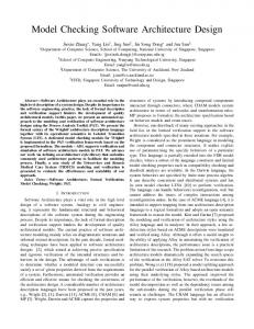
is partitioned by different values of a common attribute (Figure 2b). For example, the entity EMPLOYEE is a generalization of ENGINEER, SECRETARY, and TECHNICIAN. The generalization object (EMPLOYEE) is called an “IS-A” exclusive hierarchy because each occurrence of the entity EMPLOYEE is an occurrence of one and only one of the entities ENGINEER, SECRETARY, TECHNICIAN. 1.3 Fundamental EER Constructs The following classification of EER constructs is defined to facilitate development of a concise and easy to understand EER diagram. (1) Degree of a relationship. The degree of a relationship is the number of entities associated with the relationship. An n-ary relationship is of degree n. Unary, binary, and ternary relationships are special cases in which the degree is 1, 2, and 3, respectively. This is indicated in Figure 3. (2) Connectivity of a relationship. The connectivity of a relationship specifies the mapping of the associated entity occurrences in the relationship. Values for connectivity are either “one” or “many.” For a relationship among entities El, E2, . . . , Ei, ..., E, a connectivity of “one” for entity Ei means that given all entities except Ei, there is at most one related entity occurrence of Ei. The actual number associated with the term “many” is called the cardinality of the connectivity. Cardinality may be represented by upper and lower bounds. Figure 3 shows the basic constructs for connectivity: one to one (unary or binary relationship), one to many (unary or binary relationship), and many to many (unary or binary relationship). The shaded area in the unary or binary relationship diamond represents the “many” side, while the unshaded area represents the “one” side [Reiner et al. 19851. We use an n-sided polygon to represent n-ary relationships for n > 2 in order to show explicitly each entity associated with the relationship to be either “one” or “many” related to the other entities. Each corner of the n-sided polygon connects to an entity. A shaded corner denotes “many” Computing
Surveys, Vol. 18, No. 2, June 1986
202
l
T. J. Teorey, D. Yang, and J. P. Fry REPRESENTATION
CONCEPT
1
EXAMPLE
DEGREE
unary
binary
I
OF
ternary
CONNECTIVITY I : 1
-o-
1
DEPT
j-+jMPLOYEEI
DEPT
1 :n
EMPLOYEE CONTAINS
m:n
-+-/~IPL~Y;!---++
MEMBERSHIP CLASS
PROJECT ]
1
mandatory
optional
OFFICE
1
4
OCCUPIED-BY
EMPLOYEE
Figure 3. Fundamental EER constructs: relationship types.
and an unshaded corner denotes “one.” The ternary relationship (see Figures 3 and 6b, Section 2.1, Step 1.3) illustrates this type of association, which is much more complex than either a unary or binary relationship. An entity in a ternary relationship is considered to be “one” if only one occurrence of it can be associated with one occurrence of each of the other two associated entities. It is “many” if more than one occurrence of it can be associated with one occurrence of each of the other two associated entities. In either case, one occurrence of each of the other entities is assumed to be given. The relationship SKILL-USED in Figure 3 associates the entities EMPLOYEE, PROJECT, and SKILL. Each entity in this Computing
Surveys, Vol. 18, No. 2, June 1986
example is considered “many” (e.g., each employee with a given skill could work on many projects). This is functionally equivalent to the meaning of the functional dependencies in Figure lob (Section 3.1.3) for this relationship. In Figure 10 we see that each entity considered “one” appears on the right-hand side of exactly one FD. No entity considered “many” ever appears on the right-hand side of an FD. Equivalent FDs are used to express ternary relationships in Ling [ 19851. A ternary relationship cannot be reduced to equivalent binary relationships if the relation used to represent it is in 4NF. For example, SKILL-USED in Figures 3 and lob (Section 3.1.3) is in 4NF and cannot be
Logical Design Methodology for Relational Databases
l
203
SKILL-USED
(a) SKILL-AVAILABLE ‘4l
(b)
Figure 4. Nondecomposable and decomposable ternary relationships expressed as relations. (a) 4NF relation (nondecomposable); (b) 3NF relation decomposable to 4NF relations.
decomposed (Figure 4a). However, SKILLAVAILABLE, which has the same ER representation as SKILL-USED, is not in 4NF if all the skills of an employee can be used on all projects worked on by that employee (Figure 4b). In such a case SKILL-AVAILABLE can be decomposed into two many-to-many binary relationships between EMPLOYEE and PROJECT, and EMPLOYEE and SKILL. Each of these two new relationships represents a relation in 4NF. (3) Membership class in a relatidnship. Membership class specifies whether either the “one” or “many” side in a relationship is mandatory or optional. If an occurrence of the “one’‘-side entity must always exist for the entity to be included in the system, then it is mandatory. When an occurrence of that entity need not exist, it is considered optional. The “many” side of a relationship is similarly mandatory if at least one entity occurrence must exist, and optional otherwise. The optional membership class, defined by a “0” on the connectivity line between an entity and a relationship, is shown in Figure 3. Membership class is
implied by existence dependency in the real-world system; for example, an independent (strong) entity associated with a dependent (weak) entity cannot be optional, but the weak entity may be optional. Weak entities are sometimes depicted with a double-bordered rectangle (see Figure 2). (4) Object class of entities and relutionships. The basic objects are the n-ary relationships with their associated entities. Objects resulting from abstraction are the generalization hierarchy and the subset hierarchy (see Figure 2). The generalization hierarchy implies that the subsets are a full partition, such that the subsets are disjoint and their combination makes up the full set. The subset hierarchy implies that the subsets are potentially overlapping. 2. EER MODELING OF REQUIREMENTS (STEP 1)
The objective of requirements analysis is manifold: (1) to delineate the data requirements of the enterprise, (2) to describe the information about the objects and their associations needed to model these data ComputingSurveys,Vol. 18, No.
2, June 1986
204
.
T. J. Teorey, D. Yang, and J. P. Fry
requirements, and (3) to determine the types of transactions that are intended to be executed on the database. We use the extended entity-relationship (EER) model to describe these objects and their interrelationships, and assume natural language expressions to describe transactions. The EER model enhances the designer’s ability to capture the real data requirements accurately because it requires one to focus on greater semantic detail in the data relationships. The semantics of EER allows for direct transformations of entities and relationships to at least 1NF relations and specifies clear guidelines for integrity constraints. Also, abstraction techniques, such as generalization, provide useful tools for integration of user views to define a global conceptual schema. Further discussion of the requirements data collection process can be found in Martin [1982], Teorey and Fry [1982], and Yao [1985]. Let us now look more closely at the basic objects and their relationships that should be defined during the requirements analysis. 2.1 Design Step 1 Details Step 1.1. Classify entities and attributes. Although it is easy to define entity, attribute, and relationship constructs (cf. Section l.l), it is not so easy to distinguish their role in modeling the database. What makes an object an entity, an attribute, or even a relationship? For example, stores are located in cities. Should CITY be an entity or an attribute? Registration records are kept for each student. Is REGISTRATION-RECORD an entity or a relationship? What is a “normalized” entity? The following guidelines for classifying entities and attributes will help the designer converge to a normalized relationship database design. (1) Entities have descriptive information; identifying attributes do not. If there is descriptive information about an object, the object should be classified as an entity. If only an identifier is needed for an object, the object should be classified as an attri-
Computing
Surveys, Vol. 18, No. 2, June 1986
bute. For example, in the above store and city example, if there is some descriptive information such as STATE and POPULATION for cities, then CITY should be classified as an entity. If only CITY-NAME is needed to identify a city, then CITY should be classified as an attribute. (2) Multivalued attributes should be classified as entities. If more than one value of a descriptor corresponds to one value of identifier, this descriptor should be classified as an entity instead of an attribute, even though it does not have descriptors for itself. For example, in the above store and city example, if one store (a chain) could be located in several cities, then CITY should be classified as an entity even if it only needs an identifier CITY-NAME. (3) Mahe an attribute that has a manyto-one relationship with an entity. If a descriptor in one entity has a many-to-one relationship with another entity, the descriptor should be classified as an entity, even if it does not have its own descriptors. For example, if two entities have been defined, STORE (with identifier STORENUMBER, descriptors OWNER and CITY) and STATE, because there is a many-to-one relationship between CITY and STATE, CITY should be classified as an entity. (4) Attach attributes to entities that they describe most directly. For example, attribute OFFICE-BUILDING should be an attribute of the entity DEPARTMENT instead of the entity EMPLOYEE. (5) Avoid composite identifiers as much as possible, If an entity has been defined with a composite identifier, that is, an identifier composed of two or more attributes, and the components of the identifier are all identifiers of other entities, then eliminate this entity. The corresponding object could be defined as a relationship in a subsequent step. If an entity has been defined with a composite identifier, but components of the identifier are not identifiers of other entities, then there are two possible solutions. One is to eliminate this entity and define new entities with components of the cornposite identifier as entity identifiers, and in a subsequent step define a relationship to represent this object. The other solution
’
Logical Design Methodology for Relational Databases
is to keep the entity with the composite identifier if it is reasonably natural. As an example, if an entity REGISTRATION-RECORD has been defined, with STUDENT and COURSE as a composite identifier, then the entity REGISTRATION-RECORD could be eliminated, and two new entities STUDENT and COURSE could be defined; later in a subsequent step, a relationship between STUDENT and COURSE could be defined to represent the object REGISTRATION-RECORD. In another example, if an entity VOLLEYBALL-TEAM has been defined, with COUNTRY and GENDER as a composite identifier, then it seems suitable to keep this entity because defining an entity GENDER is not very natural. The procedure of identifying entities and attaching attributes to entities is iterative: classifying some objects as entities, attaching identifiers and descriptors to them, then finding some violation to the above guidelines, changing some objects from entity to attribute or from attribute to entity, then attaching attributes to the new entities, etc. Step 1.2. Identify the generalization hierarchies and subset hierarchies.
If there is a generalization or subset hierarchy among entities, then reattach attributes to the relevant entities. Put identifier and generic descriptors in the generic entity, and put identifier and specific descriptors in the subset entities. For example, suppose that the following entities were identified in the EER model: EMPLOYEE (with identifier EMP-NO and descriptors EMP-NAME, HOMEADDRESS, DATE-OF-BIRTH, JOBTITLE, SALARY, SKILL), ENGINEER (with identifier EMP-NO and descriptors EMP-NAME, HOME-ADDRESS, SPECIALTY), SECRETARY (with identifier EMP-NO and descriptors EMPNAME, DATE-OF-BIRTH, SALARY, SPEED-OF-TYPING), TECHNICIAN (with identifier EMP-NO and descriptors EMP-NAME, SKILL, YEARSOF-EXPERIENCE). We identify that
I
LOCATED-IN
CLUB Figure 5.
l
205
\ SCHOOL
Transitive relationships.
EMPLOYEE is a generalization of ENGINEER, SECRETARY, and TECHNICIAN. Then we reattach attributes to the entities. We put identifier EMP-NO and generic descriptors EMP-NAME, HOMEADDRESS, DATE-OF-BIRTH, JOBTITLE, and SALARY in the generic entity EMPLOYEE; we put identifier EMP-NO and specific descriptor SPECIALITY in entity ENGINEER, we put identifier EMP-NO and specific descriptor SPEEDOF-TYPING in entity SECRETARY; and we put identifier EMP-NO and specific descriptors SKILL, YEARS-OF-EXPERIENCE in entity TECHNICIAN. Step 1.3. Define relationships.
We now deal with objects that were not classified as entities or attributes, but represent associations among objects. We define them as relationships. For every relationship the following should be specified: degree, connectivity, membership class, and attributes. The following are some guidelines for defining relationships. (1) Redundant relationships should be eliminated. Two or more relationships that
are used to represent the same concept are considered redundant. Redundant relationships are more likely to result in unnormalized relations when transforming the EER model into relational schemas. Note that two or more relationships are allowed between the same two entities as long as the two relationships have different meanings. They are not considered redundant. One important case of redundancy is transitive dependency (see Figure 5). If BELONGS-TO is a many-to-one relationComputingSurveys,Vol. 18, No. 2, June 1986
206
.
T. J. Teorey, D. Yang, and J. P. Fry
(a) Figure 6.
(b) Comparison
of binary and ternary
ship between STUDENT and CLUB, LOCATED-IN is a many-to-one relationship between CLUB and SCHOOL, ATTENDS is a many-to-one relationship between STUDENT and SCHOOL, and both BELONGS-TO and LOCATED-IN are mandatory, then ATTENDS is redundant and should be eliminated. (2) Ternary relationships must be defined carefully. We define a ternary relationship among three entities only when the concept (association) cannot be represented by several binary relationships among those entities. For example, there is an association among entities TEACHER, STUDENT, and PROJECT. If each student can be involved in many projects and can work under the instruction of several teachers for any of these projects, and if each teacher can instruct many students on any project, then two binary relationships could be defined instead of one ternary relationship (Figure 6a). If, however, each student can be involved in several projects and work under the instruction of several teachers, but, if for every project the student works under the instruction of exactly one teacher, then a ternary relationship must be defined (Figure 6b). The meaning of connectivity for ternary relationships is important. Figure 6b shows that for a given pair of occurrences of STUDENT and PROJECT, there is only one corresponding occurrence of TEACHER; however, for a given pair of occurrences of TEACHER and STUDENT, there could be many corresponding occurrences of PROJECT. Step 1.4. Integrate multiple views of entities, attributes, and relationships.
Computing
Surveys, vol. 18, No. 2, June 1986
relationships.
Typically, when the design is large and more than one person is involved in requirements analysis, multiple views of data and relationships occur. These views must eventually be consolidated into a single global view to eliminate redundancy and inconsistency from the model. View integration requires the use of such extended ER semantic tools as identity (identifying synonyms), aggregation, and generalization. Recent research has advanced view integration from a representation tool [Teorey and Fry 19821 to heuristic algorithms [Elmasri and Wiederhold 1979; Navathe and Gadgil 1982; Navathe et al. 1984; Elmasri et al. 1985; Navathe et al. 19861. These algorithms are typically interactive, allowing the database designer to make decisions based on suggested alternative integration actions. Adopting an ER extension called the entity-categoryrelationship model [Elmasri et al. 19851, Navathe and others have organized the different classes of objects and relationships into forms that are either compatible or incompatible for view integration [Navathe et al. 19861. A category is defined as a subset of entities from an entity type, thus representing a form of generalization hierarchy. An object class is a set of entities that is either an entity type or category. Prior to actual integration, the algorithm performs several functions on object classes: First, it establishes naming conventions for object classes and attributes to resolve synonyms and homonyms; second, it defines the candidate keys and attribute domains for each object class; and third, it defines mappings between equivalent attributes of corresponding object classes. The
I
Logical Design Methodology for Relational Databases
l
207
PART-OF SKILL -
\
CONTAIN&
/’
BELONGS-TO
PRF-ASSOC Figure 7.
PC
Company personnel and project database (EER diagram).
integration process is applied to four possible forms of object class similarity: identical domains, contained (subset) domains, overlapping domains, and disjoint domains. Overlapping domains closely correspond to our definition of two categories related to each other in a subset hierarchy, and the disjoint domain form corresponds to a generalization hierarchy. The subset domain is similar to the relationship between a category and its generic entity type. Relationships are classified in terms of their degree, the role of each object class in the relationship, and various constraints, such as cardinality constraints, that may differ among object classes. Relationships with equal degree, the same roles, and the same cardinality constraints are easy to merge. Those with differing characteristics are more difficult and in some cases impossible to merge. Although much more work is needed to understand the semantic impact of view integration techniques, it is clear that current ER extensions have significantly
advanced the automatability integration process.
of the view
2.2 An Example Database: Company Personnel and Projects
We define a simple database design problem to illustrate the major steps in this relational database design methodology. Let us suppose it is desirable to build a company-wide database for a large engineering firm that keeps track of all personnel, their skills and projects assigned, departments worked in, and personal computers allocated. Each employee is given a job title (engineer, technician, secretary, manager). Engineers and technicians work on an average of two projects at one time, and each project could be headquartered at a different location (city). We assume that analysis of the detailed requirements for data relationships in this company results in the global-view EER diagram in Figure 7, which becomes the focal point for developing the normalized
Computing Surveys, Vol. 18, No. 2, June 1986
208
l
T. J. Teorey, D. Yang, and J. P. Fry
relations. Each relationship in Figure 7 is based on a verifiable assertion about the actual data in the company. Analysis of those assertions leads to the transformation of EER constructs into candidate relations, as shown in Figures 8-12 and summarized in Figure 13 (see Section 3). Attributes are not included in Figures 8-13 for simplicity, but are defined later in this example. As an example of view integration, the generalization of EMPLOYEE over JOBTITLE could represent the consolidation of two views of the database, one based on EMPLOYEE as the basic unit of personnel and the other based on the classification of the employees by job titles and special relationships with those classifications, such as the allocation of personal computers (PCs) to engineers.
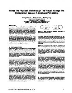
one for one of the entities, and with a unary relationship that is one to one or one to many for each entity. (3) Relationship relation with the foreign keys of all the entities that are thus related. This transformation always occurs for relationships that are binary and many to many, relationships that are unary and many to many, and all relationships that are ternary or of a higher degree. The following rules are set forth for handling null values in these transformations. Nulls are only allowed for foreign keys of any optional entity in an entity relation, but are not allowed for foreign keys of any mandatory entity in an entity relation. Nulls are also not allowed for any foreign key in a relationship relation. 3.1.1 Two Entities, One (Binary) Relationship
The one-to-one relationship between entities is illustrated in Figure 8a, b, and c. When both entities are mandatory (Figure 3.1 Transformation Rules 8a), each entity becomes a relation, and the key of either entity can appear in the other We now look at each EER construct in entity’s relation as a foreign key. One of more detail to see how each transformation rule is defined and applied. Our example is the entities in an optional relationship (see drawn from the company personnel and DEPARTMENT in Figure 8b) should contain the foreign key of the other entity in project database EER schema, illustrated in Figure 7 (Section 2.2), which indicates its transformed relation. The other entity the transformation of all types of EER (EMPLOYEE) could also contain a foreign key (of DEPARTMENT), with nulls alconstructs to relations. lowed, but would require more storage We note that the basic transformaspace because of the much greater number tions result in three types of relations of EMPLOYEE entity occurrences than [McGee 1974; Martin 1983; Sakai 1983; DEPARTMENT entity occurrences. When Hawryszkiewycz 19841: both entities are optional (Figure 8c), either (1) Entity relation with the same infor- entity could contain the embedded foreign mation content as the original entity. This key of the other entity, with nulls allowed. The one-to-many relationship is shown transformation always occurs for entities with binary relationships that are many to as either mandatory or optional on the many, one to many on the one (parent) “many” side without affecting the transformation. On the “one” side it may be either side, or one to one on one side; entities with unary relationships that are many to mandatory (Figure Bd) or optional (Figure many; and entities with any ternary or 8e). In all casesthe foreign key must appear on the ‘%nany” side, which represents the higher degree relationship, generalization child entity, with nulls allowed for foreign hierarchy, or subset hierarchy. (2) Entity relation with the embedded keys only in the optional “one” case. The many-to-many relationship, shown foreign key of the parent entity. This here as totally optional, requires a relationtransformation always occurs with binary relationships that are one to many for the ship relation with primary keys of both entity on the many (child) side and one to entities (Figure 8f). The same transforma3. TRANSFORMATION OF THE EER MODEL TO RELATIONS (STEP 2)
Computing
Surveys, Vol. 18, No. 2, June 1986
1APPRENTICEI
6
SPONSORED -BY
Every apprentice has one sponsor, andeverysponsorsponsorsone apprentice.
Every employee works in exactly one department. Every department could contain many employees.
0
CONTAINS
Relations: APPRENTICE(EMP-NO, SPON-EMP-JO) SPONSOR(SPON-EMP-NO, .: .T
Null DEPT-NO not allowed
Null SPON-EMP-NO not allowed in APPRENTICE. (4
Q
Relations : ENGINEER(EMP-NO, SECRETARYtEMP-NO,
EMP-NO) ‘---)
(4 Every professional association could have many members who are engineers, or no engineers. Every engineer could belong to many professional associations, or none. Relations : PRF-ASSOC(PA-NO.. ENGINEERtEMP-NO, BELONGS-TO(PA-Nfl
p_C-No)
Null PC-NO allowed in ENGINEER. (c) Binary
(f) relationship
,sE_C-EMP-NO) ----)
Null SEC-EMP-NO allowed in ENGINEER
( ENGINEER )
Some personal computer (PCs) are allocated to engineers, but not necessarily to all engineers.
Figure 8.
in EMPLOYEE
Each engineer can have at most one secretary. One secretary could work for several engineers.
SECRETARY
Null EMP-NO not allowed in DEPARTMENT (b)
Relations : ENGINEER(EMP-NO, PC(PC-NO, )
) .,_DEE:NC>
(4
Every department must have a manager. An employee can be a manager of at most one department.
DEPARTMENT(DEPT-NO, EMPLOYEE(EMP-NO,
Relations : DEPARTMENTtDEPT-NO, EMPLOYEE(EMP-NO,
transformation
rules.
) ) EMP-NO)
210
l
T. J. Teorey, D. Yang, and J. P. Fry
tion applies to either the optional or mandatory case. Embedded foreign keys are not possible because of the “many” property in both directions. 3.1.2 One Entity, One (Mary)
Relationship
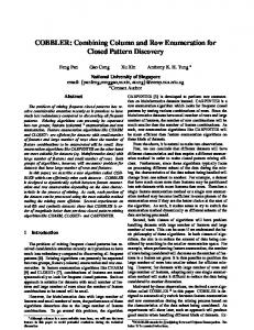
One entity with a one-to-one relationship implies some form of entity occurrence pairing, as specified by the relationship name, and this must be either completely optional or completely mandatory. In both the mandatory case (Figure 9a) and the optional case (Figure 9b) the pairing entity key appears as a foreign key in the resulting relation. In both cases the two key attributes are taken from the same domain but are given different names to designate their unique use. The one-to-many relationship requires a foreign key in the entity relation for both the optional case (Figure SC), with nulls allowed, and the mandatory case (Figure 9d), with nulls not allowed. The manyto-many relationship is shown as optional (Figure 9e) and uses a relationship relation; it could also be defined as mandatory (using the word “must” instead of “may”) but having the same transformation as the optional case. 3.1.3 n Entities, One (n-ary) Relationship @ > 2)
An n-ary relationship has n + 1 possible varieties of connectivity: all n sides with connectivity “one,” n - 1 sides with connectivity “one” and one side with connectivity “many,” n - 2 sides with connectivity “one” and two sides with “many,” and so on, until all sides are “many.” The four possible varieties of a ternary relationship are shown in Figure 10. All varieties are transformed by creating a relationship relation containing the primary keys of all n entities; in each case, however, the meaning of the keys is different. When all relationships are “one” (Figure lOa), the relationship relation consists of three possible distinct candidate keys. This represents the fact that there are three functional dependencies (FDs) needed to describe this relationship. The optional “one” allows null foreign keys; the mandatory “one” does not. Computing
Surveys, Vol. 18, No. 2, June 1986
When all relationships are “many” (Figure lob), the relationship relation is all key unless the relationship has its own attributes. In general the number of entities with connectivity “one” determines the lower bound on the number of FDs. 3.1.4 Generalization
and Subset Hierarchies
The generalization hierarchy resulting in disjoint subsets is produced by partitioning the generic entity by different values of a common attribute, for example, JOBTITLE in Figure 11. The transformation of disjoint subset generalization produces a separate relation for the whole set (the generic entity) and each of the subsets. The generic entity relation contains the generic entity key and all common attributes, including the common attribute used for partitioning. This, of course, assumes that such an attribute for partitioning actually exists. When the attribute does not exist, it must be created. Each subset relation contains the generic entity key and only attributes specific to that subset. Update integrity is maintained by requiring all insertions and deletions to occur in both the set (generic entity) relation and relevant subset relation. If the change is to the key, then one subset, as well as the set relation, must be updated. A change to a nonkey attribute affects either the set or one subset relation. Overlapping subsets are produced by partitioning the generic entity by values of different attributes (Figure 12). The transformation of this construct produces separate relations for the generic entity and each of the subset entities. The key of each relation is the key of the generic entity, and whereas the generic entity relation contains only common attributes, the subset relations contain attributes specific to that subset entity. Thus the transformation rules for the disjoint and overlapping subsets are the same. The integrity rules between these two cases are different, however. With overlapping subsets, deletion from the set (generic entity) relation cascades to anywhere from none to all of the subsets. Also, before insertion into a subset relation, it is
Logical Design Methodology APPRENTICE
Every apprentice other apprentice
w
for Relational Databases
l
211
has exactly one of the as a partner in a Project
Relations : APPRENTICE(EMP-NO,
~-E~P-~O)
PARTNER-OF
64
EMPLOYEE
An employee could have one of the other employee as his or her spouse.
v
Relations : EMPLOYEEtEMP-NO,
S_P-EE-NO) -
Null SP-EMP-NO allowed in EMPLOYEE
MARRIED-TO
(b)
Engineers are divided into groups for certain projects. Each group has a leader Relation : ENGINEER(EMP-NO,
.,_ENG=E_M_P=N@
GROUP-LEADER-OF Null ENG-EMP-NO allowed (c)
in ENGINEER.
Every apprentice tutors one of the other apprentices, One may be tutored by several other apprentices.
w
Relation : APPRENTICE(FMP-NO,
TUTORS
., _AP_P:E_M!3Q)
Null APP-EMP-NO not allowed
in APPRENTICE.
(4
PROJECT
Each project may require special communication with many other projects.
6
SPEC-COMM-WITH
Relations : PROJECT(PROJ-NO, .) SPEC-COMM-WITH(PROJ-NAME, RELA-PROJ-NAME)
(4 Figure 9.
Unary relationship
transformation
rules.
Computing Surveys, Vol. 18, No. 2, June 1986
An engineer will use one casebook for a given project. Different engineers use different casebooks for the same project. No engineer will use the same casebook for different projects, but different engineers can use the same casebook for different projects,
( ENGINEER 1
USE-CASEBOOK
PROJECT
CASEBOOK
Relations : ENGINEER(ENP-NO, 1 PROJECT(PROJ-NAME, 1 CASEBOOK(BOOK-NO, 1 USE-CASEBOOK(ENP-NO, PROJ-NAME, BOOK-NO) FDs : ENP-NO, PROJ-NAME ---> BOOK-NO BOOK-NO, PROJ-NAME ---> ENP-NO ENP-NO, BOOK-NO ---> PROJ-NAME
USE-CASEBOOK
(a) Employees use a wide range.of different skills on each project they are associated with.
ENGINEER I
lelations : .NPLOYEE(FNP-NO, 1 SKILLCSKILL-NO, 1 PROJECT(PROJ-NAME, ) SKILL-USEDVMP-NO. SKILL-NO. PROJ-NAME)
/
FDs : ENP-NO, SKILL-NO, PROJ-NO ---> @I (all key) SKILL-USED
(b) Figure 10.
Ternary
relationship
transformation
rules.
Employees are assigned to one or more projects, but can only be assigned to at most one project at a given location.
i-1 EMPLOYEE
Relations : EMPLOYEE(EMP-NO, 1 PROJECT(PROJ-NAMF, ) LOCATION(LOC-NAME, .I ASSIGNED-TO(EMP-NO. LOC-NAME,PROJ-NAME) FDs : EMP-NO. LOC-NAME ---> PROJ-NAME
ASSIGNED-TO
w
Apprentices work on projects under instructions of sponsors. No sponsor can instruct any given apprentice on more than one project. No apprentice can work on any given project under the instructlon of more than one sponsor.
APPRENTICE
A
SPONSORS
Relations : APPRENTICE(FMP-NO, ) SPONSOR(EMP-NO, ) PROJECT(PROJ-NAME, ) SPONSORS(SPON-EMP-NO, APP-EMP-NO, PROJ-NAME) FDs : APP-EMP-NO,SPON-EMP-NO ---> PROJ-NAME APP-EMP-NO,PROJ-NAME ---> SPON-EMP-NO
SPONSORS APP-EMP-NO 101 101 207 207 512 512 763
1
SPON-EMP-NO 3 9 9 4 4
9 6 (4 Figure 10.
(continued)
PROJ-NAME BETA EPSILON ALPHA DELTA GAMMA ALPHA BETA
I
214
.
T. J. Teorey, D. Yang, and J. P. Fry Different types of employees are partitioned by values of a common attribute JOB-TITLE.
JOE-TITLE
MANAGER
SECRETARY
TECHNICIAN
Figure 11.
Generalization
Relations : EMPLOYEE(EMP-NO,JOB-TITLE, common attributes) EMP.MANAGER(EMP-NO, specific attributes) EMP.SECRETARY(EMP-NO, specific attributes) EMP .TECHNICIAN(EMP-NO, specific attributes) hierarchy.
Employees with special situations are shown as overlapping subsets based on partitions on values of different attributes. Relations : EMPLOYEE(EMP-NO, common attr-lbutes) EMP.STUDENT(EMP-NO, specific attributes) EMP.POLITICIAN(EMP-NO< specific attributes) Figure 12.
Subset hierarchy.
necessary to check whether a tuple with the same key value exists in the set relation. A change to a nonkey attribute affects the set or one of the subsets. A change to a key affects the set and anywhere from none to all of the subsets. 3.1.5 Multiple Relationships
Multiple relationships among n entities are always considered to be completely independent. Each one-to-one or one-to-many relationship results in entity relations that are either equivalent or that differ only in the addition of a foreign key and thus can be merged into a single entity relation containing all foreign keys. Many-to-many relationships result in relationship relations that are unique and cannot be merged. 3.1.6 Existence-Dependent
(Weak) Entities
Weak entities differ from (strong) entities only in the need for keys from other entities Computing
Surveys, Vol. 18, No. 2, June 1986
to establish their uniqueness. Otherwise they have the same transformation properties as strong entities, and no special rules are needed. When a weak entity is already derived from two or more strong entities in the ER diagram, it can be directly transformed into an entity relation without further change. 3.1.7 Aggregation
The aggregation abstraction can occur among entities or relate attributes to a single entity [Smith and Smith 19771. Aggregation among entities, defined by the PART-OF relationship, is a special case of the collection of one-to-one or one-tomany binary relationships and can be transformed as defined in Section 3.1.1. For example, BICYCLE can represent the whole entity, while SEAT, PEDALS, HANDLEBARS, etc., represent its parts, each part being an entity with its own distinct attributes.
Logical Design Methodology for Relational Databases 3.2 Design Step 2 Details
The following transformation
steps summarize the basic rules given in Section 3.1.
Step 2.1. Transform each entity into a relation containing the key and nonkey attributes of the entity. If there is a manyto-one relationship between an entity and another (or same type) entity, add the key of the entity on the “one” side (the parent) into the relation. If there is a one-to-one relationship between an entity and another (or same type) entity, then add the key of one of the entities into the relation for the other entity. The addition of a foreign key due to a one-to-one relationship can be made in either direction. One strategy is to maintain the most natural parent-child relationship by putting the parent key into the child relation. Another strategy is based on efficiency: Add the foreign key to the relation with fewer tuples. Every entity in a generalization hierarchy or subset hierarchy is transformed into a relation. Each of these relations contains the key of the generic entity. The generic entity relation also contains nonkey values that are common to all the entities so related, and the other relations contain nonkey values specific to each subtype entity. Another option is to include all subtype attributes in the supertype (generic) entity and allow null values. Step 2.2. many binary relationship entities and ship.
Transform every many-to(or unary) relationship into a relation with the keys of the the attributes of the relation-
Step 2.3. Transform every ternary (or higher n-ary) relationship into a relationship relation using the rules given in Figure 10. Entity normalization is normally preserved under these transformations. The introduction of a foreign key into an entity relation will not result in additional functional dependencies in a normalized relation if the EER diagram is correct, that is, if all attributes are associated with the proper entities. If the EER diagram is not correct, however, additional FDs could occur, causing some denormalization. After
9
215
such a transformation, normalization could easily be reestablished using any of the well-known methods [Bernstein 1976; Fagin 1977; Ullman 1980; Lien 1981; Zaniolo and Melkanoff 1981; Maier 1983; Martin 1983; Yao 19851. 3.3 Example
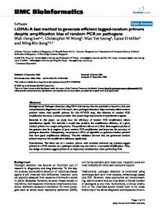
The transformation of EER diagrams to candidate relations is applied to our example database of company personnel and projects, as shown in Figures 7-12, and summarized in Figure 13. A summary of the transformation of all entities and their relationships to candidate relations (Steps 2.1-2.3) is illustrated in Table 1. Primary keys are italicized. We include some of the most typical nonkey attributes we assume have been obtained from the requirements analysis. 4. NORMALIZATION (STEP 3)
OF RELATIONS
Normalization of candidate relations is accomplished by analyzing the FDs and MVDs associated with those relations. Further analysis is then needed to eliminate data redundancies in the normalized candidate relations. 4.1 Design Step 3 Details
Step 3.1. Derive the primary the EER diagram.
FDs from
Primary FDs represent the dependencies among data elements that are keys of entities, that is, the interentity dependencies. Secondary FDs, on the other hand, represent dependencies among data elements that comprise a single entity, that is, the intraentity dependencies (see Step 3.2). Table 2 shows the type of primary FDs derivable from each type of EER construct defined in Section 1.3 and consistent with the derivable candidate relations in Figures 8-12. In fact, each primary FD is associated with exactly one candidate relation that represents a relationship among entities in the EER diagram. On the basis of the transformations in Table 2 we summarize the basic types of Computing
Surveys, Vol. 18, No. 2, June 1986
216
l
T. J. Teorey, D. Yang, and J. P. Fry SKILL
DEPARTMENT
li*ulil)
DIVISION
/OIPT-NOI
(,,,...I
SKILL-USED
PROJECT
EMPLOYEE
ASSIGNED-TO
LOCATION
EMP.MANAGER
EllP.ENGINEER
EMP.TECHNICIAN
EMPSECRETARY
BELONGS-TO PA-NO
EMP-NO
PRF-ASSOC
Figure 13. Table 1.
PC
Company personnel and project database candidate
Transformation
of Entities and Relationships
relations.
to Relations (Example)
Step 2.1. Entities to relations 1. DIVISION(DZV-NO, . . . , HEAD-EMP-NO) DEPT-NAME, ROOM-NO, PHONE-NO,. . . , DIV-NO, 2. DEPARTMENT(DEZ’T-NO, MANAG-EMP-NO) EMP-NAME, JOB-TITLE,. . . , DEPT-NO, SPOUSE-EMP-NO, 3. EMPLOYEE(EMP-NO, 4. SKILL(SKILL-NO, . . .) 5. PROJECT(PROJ-NAME, . . .) . . .) 6. LOCATION(LOC-NAME, . . .) 7. EMP.MANAGER(EMP-NO, , . .) 8. EMP.ENGINEER(EMP-NO, . . .) 9. EMP.TECHNICIAN(EMZ=-NO, 10. EMP.SECRETARY(EMZ’-NO, .) 11. PC(PC-NO, .) 12. PRF-ASSOC(PA-NO, . . .) Step 2.2. Binary or unary relationships to relations 13. BELONGS-TO(PA-NO, EMP-NO) Step 2.3. Ternary (or any n-ary) relationships to relations 14. SKILL-USED(EMP-NO, SKILL-NO, PROJ-NAME) 15. ASSIGNED-TO(EMP-NO, LOC-NAME, PROJ-NAME)
Computing
Surveys, Vol. 18, No. 2, June 1986
PC-NO)
Logical Design Methodology Table 2.
Primary FDs Derivable from EER Relationship Connectivitv
Degree Binary
1 to 1
Keycone A) + Key (one B) + Key(one A) + Keytone B) --) Keytone A) --) Key(one B) + Key(many) + Key(many) -+ Composite key
1 to l(opt) l(opt)
Unary
Ternary
to l(opt)
1 to many l(opt) to many Many to many 1 to 1 l(opt)
to l(opt)
l(opt) to many 1 to many Many to many 1 to 1 to 1
1 to many to many Many to many to many Generalization hierarchy Subset hierarchy
primary FDs derivable from EER relationship constructs: (1) key (many side) + key (one side); (2) key (one side A) + key (one side B); (3) key (many side A), key (many side B) -+ key (one side); (4) key (one side A), key (many side) + key (one side B); (5) key (one side A), key (one side B) + key (one side C); (6) composite key + 0. Types (1) and (2) represent an embedded foreign key functionally determined by the primary key in a unary or binary relationship; types (3)~(5) apply only to ternary relationships; and type (6) applies to all degrees of relationships in which the relation is represented as all key. Functional dependencies for higher degree n-ary relationships can be obtained by extending
l
217
Constructs Primarv
FD
key(one keytone keytone keycone keytone keytone keytone) keytone) + 0
B) A) B) A) B) A)
Key(one A) + key(one Keytone B) --) keyfone Keytone A) + keytone Keycone B) + key(one Key(many + key(one) Key(many) + key(one) Composite key + 0
1 to 1 to many
(3)-(6).
for Relational Databases
B) A) B) A)
Key(A), key(B) ---) key(C) Key(A), key(C) -+ key(B) Key(B), key(C) + key(A) Keytone A), key(many) + key(one B) Keycone B), key(many) + key(one A) Keycmany A), key(many B) + key(one) Composite key + 0 (Secondary FD only) (Secondary FD only)
Step 3.2 Examine all the candidate relations for MVDs and secondary FDs.
Each candidate relation is examined to determine what dependencies exist among primary key, foreign key, and nonkey attributes. If the EER constructs do not include nonkey attributes, the data requirements specification (or data dictionary) must be consulted. Step 3.3. Normalize all candidate relations to the highest degree desired, eliminating any redundancies that occur in the normalized relations.
Each candidate relation now has possibly some primary FDs, secondary FDs, and MVDs uniquely associated with it. These dependencies determine the current degree of normalization of the relation. Any of the well-known techniques for increasing the degree of normalization can now be applied to each relation, with the desired degree as stated in the requirements specification. The elimination of data redundancy tends to minimize storage space and update cost without sacrificing data integrity. Integrity is maintained by constraining the Computing Surveys, Vol. 18, No. 2, June 1986
218
l
T. J. Teorey, D. Yang, and J. P. Fry
new relation schema to include all data dependencies existing in the candidate normalized relation schema. A relation B that is subsumed by another relation A can be potentially eliminated. Relation B is subsumed by another relation A when all the attributes in B are also contained in A and all data dependencies in B also occur in A. As a trivial case, any relation containing only a composite key and no nonkey attributes is automatically subsumed by any other relation containing the same key attributes, because the composite key is the weakest form of data dependency. If, however, relations A and B represent the generic and specific cases, respectively, of entities defined by the generalization (or subset) hierarchy abstraction, and A subsumes B because B has no additional specific attributes, the designer must collect and analyze additional information to decide whether or not to eliminate B. A relation can also be subsumed by the construction of a join of two other relations (a “join” relation). When this occurs, the elimination of a subsumed relation may result in the loss of retrieval efficiency, although storage and update costs will tend to be decreased. This trade-off must be further analyzed in physical design with regard to processing requirements to determine whether elimination of the subsumed relation is reasonable. 4.2 Example
In Step 3.1 we obtain the primary FDs by applying the rules in Table 2 to each relationship in the EER diagram in Figure 7. The results are shown in Table 3. In Step 3.2 we determine the secondary FDs and MVDs from the EER diagram or requirements specification. Let us assume that the dependencies given in Table 4 are derived from the requirements specification. Normalization of the candidate relations is accomplished in Step 3.3. In Table 1, only the DEPARTMENT relation is not at least 3NF due to the transitive functional dependency DEPT-NO + ROOM-NO + PHONE-NO. This is easily resolved by creating the relation ROOM(ROOM-NO,
Computing
Surveys, Vol. 18, No. 2, June 1986
Table 3. Functional Dependencies Derived from the EER Diaaram IExamoleI 1. 2. 3. 4. 5. 6. 7. 8. 9. 10. 11. 12. 13. 14.
DIV-NO + HEAD-EMP-NO HEAD-EMP-NO -+ DIV-NO DEPT-NO + DIV-NO DEPT-NO + MANAG-EMP-NO MANAG-EMP-NO + DEPT-NO EMP-NO + DEPT-NO EMP-NO + JOB-TITLE EMP-NO + SPOUSE-EMP-NO SPOUSE-EMP-NO + EMP-NO EMP-NO + PC-NO PC-NO + EMP-NO EMP-NO, SKILL-NO, PROJ-NAME + 0 EMP-NO, LOC-NAME + PROJ-NAME EMP-NO, PA-NO --+ 0
Table 4.
Secondary Functional Dependencies (Example)
1. 2. 3. 4.
DEPT-NO + DEPT-NAME DEPT-NO -+ ROOM-NO ROOM-NO + PHONE-NO EMP-NO + EMP-NAME
PHONE-NO) and deleting PHONE-NO from the DEPARTMENT relation. This example contains no data redundancies that can be eliminated without losing some degree of normalization. In Table 1 neither SKILL-USED nor ASSIGNEDTO relations can be subsumed by joins of other relations. SKILL-USED has been defined as 4NF and cannot be lossless decomposed. ASSIGNED-TO contains the functional dependency EMP-NO, LOCNAME + PROJ-NAME, which cannot be reconstructed with any of the other relations. Thus the final normalized relations are now completely defined (Table 5). In general, we observe that the candidate relations are good estimators of the final schema and normally require very little refinement. 5. REFINEMENTS TO THE LOGICAL DESIGN PROCESS 5.1 Addition of More Semantics to Conceptual Modeling
Conceptual modeling of databases is by no means confined to the ER approach. A number of other schools of thought have received attention and some perhaps offer
Logical Design Methodology for Relational Databases Table 5. 1. 2. 3. 4. 5. 6. 7. 8. 9. 10. 11. 12. 13. 14. 15. 16.
l
219
Normalized Relations (Example)
DIVISION(DZV-NO. HEAD-EMP-NO. . . .) DEPARTMENT(Dk”-NO, DEPT-NAME, ROOM-NO,. . , DIV-NO, MANAG-EMP-NO) EMPLOYEE(EMP-NO, EMP-NAME, JOB-TITLE,. . . , DEPT-NO, SPOUSE-EMP-NO, SKILL(SKILL-NO, . .) PROJECT(PROJ-NAME, . . .) LOCATION(LOC-NAME, .) EMP.MANAGER(EMP-NO, . . .) EMP.ENGINEER(EMP-NO, . . .) EMP.TECHNICIAN(EMP-NO, . . .) EMP.SECRETARY(EMP-NO, . . .) PC(PC-NO, . . .) PRF-ASSOC(PA-NO, . . .) BELONGS-TO(PA-NO, EMP-NO) SKILL-USED(EMP-NO. SKILL-NO. PROJ-NAME) ASSIGNED-Tb(EMP-hi0, LOC-NAME, PROJ-NAME) ROOM(ROOM-NO, PHONE-NO)
a richer semantic base than the ER model. The application of the semantic network model to conceptual schema design was shown by Bachman [1977] and McLeod and King [1979], and the binary relationship model concepts were studied by Abrial [1974], Bracchi et al. [1976], Nijssen et al. [1979], IS0 [1982], and Kent [1984]. The significant semantic network concepts have been incorporated into the EER model described here, but the binary relationship model incorporates considerably more semantics than either the ER or EER models [ISO 19821. Other extensions to the original ER model, such as the inclusion of the time dimension, have also been described elsewhere [Bubenko 1977; Clifford and Warren 1983; Ferg 19851. The binary relationship approach is the basis of the information analysis method called NIAM [Verheijen and Van Bekkum 19821. This approach defines a lexical object type, nonlexical object type, and role; these roughly correspond to the attribute, entity, and relationship concepts in the ER model. However, the binary relationship model tries to avoid making entity-attribute decisions as early in the conceptual modeling process as with the ER model. One difference between the models is that role names in the binary relationship model are directional between two lexical object types or between a lexical and nonlexical object type. The binary relationship model also includes the EER concepts of subtyping (generalization), relationship connec-
PC-NO)
tivity (cardinality), and membership class (mandatory or optional existence). One of the most significant advantages of the binary relationship model is the inclusion of constraints on role occurrences: identifier, subset, equality, uniqueness, and disjoint. Identifiers are included in the ER model, but not all the variations explicitly defined in the binary relationship model. The disjoint constraint can be modeled by the generalization and subset hierarchies in EER, but the subset, equality, and uniqueness contraints have no equivalent in EER. Further work is needed to investigate the potential of these constraints as additional extensions to the ER model and whether semantic equivalence can be achieved between these (and other) approaches. 5.2 Relation
Refinement
for Usage Efficiency
Database design techniques for network and hierarchical systems often make use of processing requirements to refine the logical schema before the physical design phase if there are obvious large efficiency gains to be made [Teorey and Fry 1982; Bertaina et al. 1983; Hawryszkiewycz 19841. The justification for this approach is that once physical design begins, the logical schema is considered to be fixed and is thus a constraint on efficiency. The database designer would obviously like to remove this inflexibility if possible. A similar technique would be useful in relational database design if it were to result in more efficient database
Computing Surveys, Vol. 18, No. 2, June 1986
220
l
T. J. Teorey, D. Yang, and J. P. Fry
schemas without loss of data integrity and were relatively easy to implement. This approach is not considered part of logical design by many, whereas others define it as a separate step between logical and physical design. We take the latter view and think of it as a prephysical design step, definitely not part of conceptual design, but potentially an extension of logical design defined as broader in scope than conceptual design. Regardless of where this step belongs, its goal is to refine a relational schema. Its algorithm is based on a processoriented or usage view of the data to increase the database efficiency for current processing requirements and yet retain all the information content of the functional dependency or natural view of data. Thus the database would still be an accurate representation of real-world relationships, more efficient, and potentially more adaptable to future processing requirements. The results of this algorithm could be used to specify alternative logical structures to be considered during physical design, and thus provide the physical designers with more feasible solutions to choose from. More efficient databases are therefore likely to be defined. One approach is to assume that all attributes are initially assigned to relations on the basis of functional dependencies, and that the relations are at least 3NF. Efficiency for the current query requirements could increase by redundantly adding attributes, used together in a query, to an existing relation so that all attributes needed for that query would reside in a new relation, called a join relation. This is known as materializing the join [Schkolnick and Sorenson 19801. Query processing time might be greatly reduced because fewer joins would be needed. However, the side effects of this redundancy include an increase in storage space required, an increase in the update and referential integrity cost, potential denormalization and loss of integrity, and program transformations for all applications containing joins that are materialized. Further research is needed to demonstrate the practicality of this step.
Computing
Surveys, Vol. 18, No. 2, June 1986
6. CONCLUSION We have shown that a practical step-bystep methodology for relational database design can be derived using a variety of extensions to the ER conceptual model. The methodology has been illustrated with a simple database design problem, showing each design step in detail. The strategy of first modeling the natural data relationships and later refining the design for normalized relations was emphasized as clearly separable phases. The methodology produces nearly reproducible designs from a given requirements specification and can be easily implemented as an interactive database design tool. APPENDIX:
SUMMARY OF LOGICAL RELATIONAL DATABASE DESIGN STEPS
1. Extended ER (EER) modeling of requirements 1.1 Identify entities and attach attributes to each. 1.2 Identify generalization and subset hierarchies. 1.3 Define relationships. 1.4 Integrate multiple views of entities, attributes, and relationships. 2. Transformation of the EER model to relations 2.1 Transform every entity into one relation with the key and nonkey attributes of the entity. 2.2 Transform every many-to-many binary (or unary) relationship into a relationship relation. 2.3 Transform every ternary (or higher n-ary) relationship into a relationship relation. 3. Normalization of relations 3.1 Derive the primary FDs from the EER diagram. 3.2 Examine all the candidate relations for MVDs and secondary FDs. 3.3 Normalize all candidate relations to the highest degree desired, eliminating any redundancies that occur in the normalized relations.
Logical Design Methodology for Relational Databases ACKNOWLEDGMENTS The authors wish to thank Emerson Hevia and the referees for their critique of the manuscript. REFERENCES ABRIAL, J. 1974. Data semantics. In Data Base Management, Proceedings of the ZFZP TC2 Conference
(Cargese, Corsica). North-Holland, Amsterdam. ATZENI, P., BATINI, C., LENZERINI, M., AND VILLANELLI, F. 1981. INCOD: A system for conceptual design of data and transactions in the entity-relationship model. In Entity-Relationship Approach
to Information
Modeling
and Analysis.
ER Institute, Saugus, Calif. BACHMAN,C. 1977. The role concept in data models. In Proceedings of the 3rd International Conference on Very Z&ge’Data Bases (Tokyo, Oct. 6-8). IEEE, New York, pp. 464-476. BEERI, C., BERNSTEIN, P., AND GOODMAN, N. 1978. A sophisticate’s introduction to database normalization theory. In Proceedings of the 4th International Conference on Very Large Data Bases (Berlin, Sept. 13-15). IEEE, New York,
pp. 113-124. BERNSTEIN, P. 1976. Synthesizing 3NF Relations from functional dependencies. ACM Trans. Database Syst. I, 4 (Dec.), 272-298. BERTAINA, P., DILEVA, A., AND GIOLITO, P. 1983. Logical design in CODASYL and relational environments. In MethodoZogy and Tools for Data Base Design, S. Ceri, Ed. North-Holland, Amsterdam, pp. 85-117. BRACCHI, G., PAOLINI, P., AND PELAGAT~I, G. 1976. Binary logical associations in data modelling. In Modelling in Data Base Management Systems, Proceedings of the ZFZP TC2 Conference
(Freudenstadt, West Germany). North-Holland, Amsterdam. BRIAND, H., HABRIAS, H., HUE, J., AND SIMON, Y. 1985. Expert system for translating an E-R diagram into databases. In Proceedings of the 4th international Conference on EntityIRekionship Approach (Chicago). IEEE Computer Society
Press, Silver Spring, Md., pp. 199-206. BUBENKO, J. 1977. The temporal dimension in information modelling. In Architecture and Models in Data Base Management Systems, G. Nijssen, Ed. North-Holland, Amsterdam. CHEN, P. 1976. The entity-relationship modelToward a unified view of data. ACM Trans. Database Syst. 1, 1 (Mar.), 9-36. CHUNG, I., NAKAIUURA,F., AND CHEN, P. 1981. A decomposition of relations using the entityrelationship approach. In Entity-Relationship Approach to Information
Modeling
and Analysis,
P. Chen, Ed. North-Holland, Amsterdam. CLIFFORD, J., AND WARREN, D. 1983. Formal semantics for time in databases. ACM Trans. Database Syst. 8, 2 (June), 214-254.
l
221
CODD, E. 1970. A relational model for large shared data banks. Commun. ACM 13, 6 (June), 377-387. CODD,E. 1974. Recent investigations into relational data base systems. In Proceedings of the ZFZP Congress. North-Holland, Amsterdam. DATE, C. 1984. A Guide to DB2. Addison-Wesley, Reading, Mass. DATE, C. 1985. An Introduction to Database Systems, vol. 1,4th ed. Addison-Wesley, Reading, Mass. ELMASRI, R. AND WIEDERHOLD, G. 1979. Data model integration using the structural model. In Proceedings of ACM SZGMOD International Conference on Management of Data (Boston,
May 30June 1). ACM, New York, pp. 319-326. ELMASRI, R., HEVNER, A., AND WEELDREYER, J. 1985. The category concept: An extension to the entity-relationship model. Data Knowl. Eng. 1, 1, 75-116. FAGIN, R. 1977. Multivalued dependencies and a new normal form for relational databases. ACM Trans. Database Syst. 2,3 (Sept.), 262-278. FERG, S. 1985. Modeling the time dimension in an entity-relationship diagram. In Proceedings of the 4th Znternationnl Conference on the Entity-Relationship Approach (Chicago). IEEE
Computer Society Press, Silver Spring, Md., pp. 280-286. HAWRYSZKIEWYCZ,I. 1984. Database Analysis and Design. SRA, Chicago. HOWE, D. 1983. Data Analysis and Data Base Design. Arnold, London. IS0 1982. Concepts and terminology for the conceptual schema and the information base. J. van Griethuysen, Ed. ISO/TC97/SCS/WG3-N695 Report. ANSI, New York, 180 pp. JAJODIA,S., AND NC, P. 1983. On the representation of relational structures by entitycrelationship Diagrams. In The Entity-Relationship Approach to Software Engineering; G. C. Davis-et al., Eds. Elsevier North-Holland, New York, pp. 223-248. JAJODIA,S., AND NC, P. 1984. Translation of entityrelationship diagrams into relational structures. J. Syst. Softw. 4, 123-133. KENT, W. 1981. Consequences of assuming a universal relation. ACM Trans. Database Syst. 6, 4 (Dec.), 539-556. KENT, W. 1984. Fact-based data analysis and design. J. Syst. Softw. 4,99-121.
LENZERINI, M., AND SANTUCCI,G. 1983. Cardinality constraints in the entity-relationship model. In The Entity-Relationship Approach to Software Engineering, G. C. Davis et al., Eds. Elsevier
North-Holland, New York, pp. 529-549. LIEN, Y. 1981. Hierarchical schemata for relational databases. ACM Trans. Database Syst. 6, 1 (Mar.), 48-69. LING, T. 1985. A normal form for entity-relationship diagrams. In Proceedings of the 4th International Conference on the Entity-Relationship
Computing
Approach
Surveys, Vol. 18, No. 2, June 1986
222
l
T. J. Teorey, D. Yang, and J. P. Fry
(Chicago). IEEE Computer Society Press, Silver Spring, Md., pp. 24-35. MAIER, D. 1983. Theory of Relational Databases. Computer Science Press, Rockville, Md. MARTIN, J. 1982. Strategic Data-Planning Methodologies. Prentice-Hall, Englewood Cliffs, N.J. MARTIN, J. 1983. Managing the Data-Base Environment. Prentice-Hall, Englewood Cliffs, N.J. MCGEE, W. 1974. A contribution to the study of data equivalence. In Data Base Management, J. W. Klimbie and K. L. Koffeman, Eds. NorthHolland, Amsterdam, pp. 123-148. MCLEOD, D., AND KING, R. 1979. Applying a semantic database model. In Proceedings of the 1st International Conference on the EntityRelationship Approach to Systems Analysis and Design (Los Angeles). North-Holland, Amster-
dam, pp. 193-210. NAVATHE, S., AND CHENG, A. 1983. A methodology for database schema mapping from extended entity relationship models into the hierarchical model. In The Entity-Relationship Approach to Software Engineering, G. C. Davis et al., Eds. Elsevier North-Holland, New York. NAVATHE, S., AND GADGIL, S. 1982. A methodology for view integration in logical database design. In Proceedings of the 8th International Conference on Very Large Data Bases (Mexico City). VLDB Endowment, Saratoga, Calif., pp. 142-152. NAVATHE, S., SASHIDHAR, T., AND ELMASRI, R. 1984. Relationship merging in schema integration. In Proceedings of the 10th International Conference on Very Large Data Bases (Singapore). VLDB Endowment, Saratoga, Calif., pp. 78-90. NAVATHE, S., ELMASRI, R., AND LARSON, J. 1986. Integrating user views in database design. IEEE Computer 19, 1, 50-62. NIJSSEN, G., VAN ASSCHE, F., AND SNIJDERS, J. 1979. End user tools for information systems requirement definition. In Formal Models and
SAKAI, H. 1983. Entity-relationship approach to logical database design. In Entity-Relationship Approach to Software Engineering, C. G. Davis, S. Jajodia, P. A. Ng, and R. T. Yeh, Eds. Elsevier North-Holland, New York, pp. 155-187. SCHEUERMANN,P., SCHEFFNER,G., AND WEBER, H. 1980. Abstraction capabilities and invariant properties modelling within the entity-relationship approach. In Entity-Relationship Approach to Systems Analysis and Design, P. Cben, Ed. North-Holland, Amsterdam, pp. 121-140. SCHKOLNICK, M., AND SORENSON, P. 1980. DENORMALIZATION: A performance oriented database design technique. In Proceedings of the AZCA 1980 Congress (Bologna, Italy). AICA, Brussels, pp. 363-377. SMITH, H. 1985. Database design: Composing fully normalized tables from a rigorous dependency diagram. Commun. ACM 28,8 (Aug.), 826-838. SMITH, J., AND SMITH, D. 1977. Database abstractions: Aggregation and generalization. ACM Trans. Database Syst. 2,2 (June), 105-133. SWEET, F. 1985. Process-driven data design. Datamation 31,16,84-85, first of a series of 14 articles. TEOREY, T., AND FRY, J. 1982. Design of Database Structures. Prentice-Hall, Englewood Cliffs, N.J. ULLMAN, J. 1980. Principles of Database Systems. Computer Science Press, Potomac, Md. VERHEIJEN, G., AND VAN BEKKUM, J. 1982. NIAM: An information analysis method. In Information Systems Design Me0wdolagies, Olle, Sol, and Verrvn-Stuart. Eds. North-Holland, Amsterdam, pp. 537-590. WEBRE, N. 1981. An Extended E-R model and its use on a defense project. In Proceedings of the 2nd International Conference on the EntityRelationship Approach, (Washington, D.C.).
North-Holland, Amsterdam, pp. 175-194. WONG, E., AND KATZ, R. 1980. Logical design and schema conversion for relational and DBTG databases. In Entity-Relationship Approach to Systems Analysis and Design, P. Chen, Ed. NorthHolland, Amsterdam, pp. 311-322. Practical Tools for Information System Design, H. Schneider, Ed. North-Holland, Amsterdam. YANG, D., TEOREY,T., AND FRY, J. 1985. A practical approach to transforming extended ER diagrams OREN, 0. 1985. Integrity constraints in the coninto the relational model. Computing Research ceptual schema language SYSDOC. In ProceedLaboratory CRL-TR-6-85, Electrical Engineerings of the 4th International Conference on the ing and Computer Science Dept., Univ., of Entity-Relationship Approach (Chicago). IEEE Michigan, Ann Arbor. Computer Society Press, Silver Spring, Md., pp. 288-294. YAO, S. 1985. Principles of Database Design: Vol. 1, Logical Organizations. Prentice-Hall, Englewood REINER, D., BRODIE, M., BROWN, G., FRIEDELL, M., Cliffs, N.J. KRAMLICH, D., LEHMAN, J., AND ROSENTHAL, A. 1985. The database design and evaluation ZANIOLO, C., AND MELKANOFF, M. 1981. On the workbench (DDEW) project at CCA. Database design of relational database schemas. ACM Eng. 7,4,10-15. Trans. Database Syst. 6, 1 (Mar.), l-47.
Received January 1986; revised May 1986; final revision accepted September
ComputingSurveys,Vol. 18,No. 2, June 1986
1986.