_,
‘. “I’
KNOWLEDGE
BASE FOR DATABASE
DESIGN
J.J.Korczak, L.A.Maciaszek, G.J.Stafford The University of Wollongong Departmentof Computing Science P.O.Box 1144, Wollongong. N.S.W. 2500. Australia ABSTRACT
1. INTRODUCTION
This paper describes the database design knowledge of a computer-assisteddatabasedesign tool, called the Intelligent DatabaseDesign Kit (IDDK): useil to develop databasesy&ms. The IDDK knowledge base1sstored in the form of a database dictionary based on an extended entity-relationship-ataibute model. The database dictionary is central to the knowledge engineering approachof the IDDK implementation strategy.The knowledge-baseddictionary is a repository of meta-data(atomic facts, concepts. definitions, inference rules, heuristics) for a databasesystemdevelopment.IDDK tools are developed using, to a large extent, semantic models and artificial intelligence techniques. The paper introduces computer-assistedextensions to Chen’s entity-relationship model, in particular, recursive, subset, generic, and nested relationship concepts. An architecture and framework for intelligent databasedesign is presented. The databasedesign knowledge is divided into a declarativepart (containing a description of entities, relationships and attributes) and a procedural part (defining design operations). While driving the IDDK tools, the knowledge base maintains basic consistency checks. In fact, the same methodology that supportsthe databasedesign activities is used to implement the knowledge base.The IDDK interface to the knowledge base editor is based on a standard Macintosh interface extended with databasedesign-oriented pallette icons and graphical editing tools.
Retrospectively, database design has relied ujton human experience and judgement rather than mechanistic algcnithmS. The design task is usually performed by vltperts who obtain information about the users’ needs through interviewing, examining existing documentation, and other traditional means. To this extent, the current approach suffers from two weaknesses:(1) it requires the use of a scarce resource - the expert databasedesigner, and (2) the designer’s knowledge of the application is necessarily second-band and some of its intricacies ,are likely to be overlooked. In our research, we respond to these problems by providing: (1) an expert system basedset of tools, (2) a large lmowledge base;ISa repository for information about the application and design activities.
Categories and Subject Descriptors: D.2 [Software Engineering]: D.2.1 Requirements/Specifications, D.2.10 Design; H.2 [Database Management]: Data dictionary/directory; I.2 [Artificial Intelligence]: 1.2.4 Knowledge RepresentationFormalisms and Methods, 12.5 ProgrammingLanguagesand Software. Additional Keywords and Phrases: Aggregation, Conceptualization, Data Dictionary, Declarative Knowledge, Entity-Relationship-Attribute Model, Expert System, Generalization; Inference Engine, Knowledge Base,Procedural Knowledge, User Interface. Permission to copy without fee all or part of this material is granled provided thar the copies are not made or distributed for direct commercial advantage, the DASFAA copyright notice and the litle of the publication and its date appear, and notice is given that copying is by permission of the Organizing Committee of the International Symposium on Database Syslems for Advanced Applications. To copy otherwise, or to republish. requires a fee and /or special permission from the Organizing Commitlee.
The Intelligent Database. Design Kit (IDDK) is a knowledge engineering project which integrates database technology. software engineering, and knowledge-based techniques. A key concept in this research is the use of a semantically extended conceptual model (entity-relationship (Chcn, 1976)) as the underlying formalism of the database design knowledge base, which in turn drives the IDDK tools. The paper extends the fonhcoming ANSI and IS0 standardsfor Information Resource Dictionary System IRDS (Dolk and Kirsch II, 1987; Goldfine, 1985).The extension is threefold: (1) it applies a knowledge-based technology to computer-assisted design environments. (2) it uses expkit database design knowledge, (3) it relate&. to, the life-cycle of system development. IDDK is concernedwith an entire’databasedevelopment life-cycle: requirements anaiysis, conceptual, logical and physical database modelling, application software d&sign, maintenanceand evolution. The methodology is process-driven; data semantics are derived from the semantics of business functions and any performance-motivated refinements and modifications of data structures, are, validated against the specifications of functions. In an overall IDDK approach. the design begins wi!h the identifloatlon of businessprocessesand data flows. IDDK includes a tool to draw data flow diagrams. The diagrams are used to derive afust-cut conceptual structure. which is then refined and converted $0 a relational logical structure. IDDK keeps track of completed transforms and ensures the coordination among s@s and the integrity of the logical stmcturebeing derived. The emphasis of this pa r is on the database design knowledge of IDDK. The IDD k knowledge base is expressed as a semantic net that is an extension of Chen’s entityrelationship model (Chen, 1976).IDDK knows the fun@mental concepts such as entity, relationship, attriiute, as well as the extensions such as recursive relationship; subset relationship, generic relationship, nested relationship, &normalized object,
International Symposium on Database Systems tar Advanced Applications -61 -
Seotil, Korea, April, 1989
and modeling heuristics. An extended entity-relationshipattribute (BRA) model, built in IDDK, offers mechanismsfor the representation and organization of knowledge. In contrast to application-oriented knowledge, databasedesign knowled e once customized - is not expected to undergo changes. ht design knowIedge for application development is unique to lDDK and relatively static. The database&sign knowledge is obtained from database experts and encodedin IDDK,Tht design knowledge is divided into declarative and procedural knowledge (Frost, 1986, Keller, 1987).Declarati~c knowledee emohasizesthe “static” asceetof database design - entities, relationships, attribute& The procedural knowledge emphasizes the “dynamic” aspect of database design and defines how to USCthe declarative knowledge in the design process. The declarative knowledge and procedural knowledge are integrated in a common framework and can be usedfor various phasesof the systemlife cycle. The paper is organized as follows. In the next section, the framework for intelligent database design is discussed. A detailed diagram of the lDDK tools for the databasedesign life cycle is also introduced. In Section 3, our approachto database design knowledge is described. The description of the knowledge baseeditor is given and the structure of declarative and procedural knowledge for database design is presented. Simple examples are used to illustrate some fine points of a knowledge-basedapproachto databasedesign. 2. FRAMEWORK DESIGN 2.1.
Principles
FOR INTELLIGENT
6. M&renance of the &mbase (security. integrity, recovery, backup,authorization, auditing, tuning); 7. Evolution (restructuring, reorganization, application software conversion). Of the seven phases, requirements analysis and specification and conceptual modeling are indtpendent of the DBMS chosenfor the databasedevelopment.The remaining five phasesapply separately for the relational, network, and micro environments. The overall design process is iterative. Feedback is expected and complied with. As an illustration, the general design procedure at the conceptua1 level can be defined as follows: s.. sot database-design-knowledge: rmrd application_knowledge-state; S = application-knowledge-state;
... procdure
application-domain_designISJ; var design unfinished, stop design: design-unfznished + truefstop-design + false; while design-unfinished
begin identify
transitions
T of
applicable
on S
T=IT-entitY/T-relationship, T-connection, T-edftingJ read selected-transition ift(iJ e T
DATABASE
than of IDDK
a set
Development
IDDK tools are being developedwith the use of semanticmodels and artificial intelligence techniques.The semanticcomponentis centeredaround the abstraction mechanisms(Smith and Smith, 1977). Recent advances in semantic modeling are taken advantageof (Brodie and Mylopoulos. 1986; Maciaszek, 1989; Stachowitz, 1985; Su, 1985). The applied artificial intelligence techniques concern mainly the knowledge representation formalism, reasoning and knowledge acquisition methods (Frost, 1986; Keller, 1987; Michalski er al., 1983). The IDDK design methodology covers all phasesof the databasedevelopmtnt. We have identified seven phasesof the databasedesign life cycle: 1. Requirements analysis amispecificarion (strategicplanning, tactical modelling, document flows, defining data flow 2. Conceptual modeling (functions specifications, derivation of design ranks, view integration, clustering of attributes, defining entities and relationships, using abstractions and 3. Design of the logicat schema (derivation of feasible logical structure, designing logical objects (records, sets,baseand view tables, data items, etc.), verification and refinement pmcedutw logical schema definition); 4. Design of the the physical schema (derivation of feasible physical structuie, gross and fine placement, accesspath optimizatiott, spacerequirements, performanceprediction, physical schemadefinition); 5. Progrummmg of user applications (designinginteractive and batch applications, enforcing semantic integrity of the database, deriving programs from databasestructures and business functions, screen (form) and report generation, programmingin the host languageenvironment); - 62 -
else
end;
boolean;
T-attribute,
t(i);
begin apply
t(i)
S e
new-S;
on S + new-S;
and;
send an error-message; read stop-design; if stop-design then begin save S in application_knowledge_state; design-unfinished c end application-domain-design:
false:
Each step of the database design process can be characterized by a state and a set of applicable transitions. The are many ways in which one can select and apply transitions on a current stateof a conceptual schemadesign. The simplest way istoevaluatetheconditionsinall ruleswithrespecttothe curent stateof database design. Statesand transitions are constrained.This meansthat the statewhich is obtained when transition t occurs has to satisfy the appropriateconstraints.ln general, (S&k+j) A F*(filCtj)) -+ si+l(-%+l/Csi+l) where Si denotesa set of assetdons in the databasedictionary in stepi. Fr(t/ct) is a set of forn%las affected by the transition ti, CS and ct are sets of constraints on states and transitions respectively. 2.2. IDDK Architecture lDDK consists of five modules. Bach module contains specific and independent information, data structures and procedures.
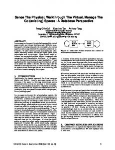
The modules are: Knowledge Acquisition, Database Design Knowledge, Application Domain Knowledge, Inference Engine, and User Interface (Figure 1). DATABASE DESIGN KNOWLEDGE
*-
KNOWLEDGE ACQUiSITION
APPLICATION
Figure
1 IDDK
Architecture.
The knowledge acquisition module is in charge of extracting databasedesign knowledge and submitting it to the knowledge basemodule. The IDDK knowledge baseconsists of two types of knowledge which differ in content, in acquisition method and in usage. The first, databasedesign knowledge is acquired by being programmed by a knowledge engineer (databaseexpert). The design knowledge is defined as a set of design states and transitions; both restricted by a set of constraints. The secondtype of knowledge, application domain knowledge is acquired by being “drawn and typed”. This is a form of learning from instruction (Michalski et al., 1983). Acquiring domain knowledge from an application database designer, requires that the IDDK programs interpret the text typed or graphical symbols used, and transform them into an internal representation. The IDDK inference engine performs inferences on user-defined information, checks integrity constraints, and finally augments the existing application knowledge. The knowledge editor provides features to create, modify and document application knowledge. The editor aids the designer in organizing knowledge and supporting incremental acquisition. A databasedesigner can instruct the systemto change,validate or refute information it has been told previously. In IDDK, a set of readily understandablequestions and help pagesis implemented for eliciting knowledge from the system designer. The user interface of the knowledge editor is presentedin Section 3 of the paper. The IDDK database design knowledge is a collection of concepts,objects,integrity constraints, rules and operations that apply in the databasedesign. The databasedesign knowledge is divided into two parts: declarative (static) knowledge and procedural (behavioral) knowledge. The static knowledge is representedby meansof an enhancedentity-relationship-attribute (ERA) model. The semantics of the knowledge base, in enhanced ERA representation, are declarative. However, as a semantically poor relational database technology is used to implement the knowledge base, some of these declarative semanticsare implemented in procedural databasetriggers and demons (and moved to the inference engine). As a result, a limited and carefully monitored volume of deduction is traded for, calculation (unavoidable phenomenon in any large knowledge-based system, for feasibility and performance - 63-
reasons). The procedural knowled@ refers to modeling of design actions and to keeping srack of the database design processes.Especially, it incorporates the side effects of actions and the consistency checks. ‘The knotildge editor (IDDK, 1988) applies to these two parts of databasedesign knowledge. Another tool of IDDK is usedto achieve a fmt-cut conversion of the domain knowledge from its conceptual model to a relational schema (Maciaszek : et ol., 1988). TKe database design knowledge is discussedin the next section of the paper. The application domain knowledge contains the descriptions of concepts,objeots.integrity constraints, rules and operations concerning a given application domain. In other words, it contains the results of IDDK-controlled database design process.The application knowledge is also composedof declarative and procedural ‘knowledge. That knowledge is application domain specific, i.e. a separate database is maintained for each databasedesign project. There is only one body of design knowledge for a customized installation of IDDK. However, multiple domain-centeredknowledge can be maintained by a designer who uses a customized IDDK (the customization will normally be necessaryto provide the user with a required subsetof IDDK taols, e.g. different subsetswill be required for the designers of relational and network databases).Development of application domain knowledge is controlled by the inference engine using the databasedesign knowledge. At the time of-writing, a number experimental domain knowledge bases (e.g. bank cnstomer services, inventory control, etc.) have been developed using IDDK and implementedunder Oracle. Before the presentation of the IDDK inference engine, let us consider strucmral and behavioral aspectsof-databasedesign. The database design knowledge has relatively few rules and facts compared with the number of activities, rules and facts in an application domain. It wouid seem appropriate to consider the rules which effectively govern the way in which a database design state may be transformed into another. The database design knowledge can be.regarded as a hierarchy of classes, where classes are defined as being: objects (entities and relationships), connections or attributes. These classescan be related to each other in various but definite ways to result in a semantic model of a given application. Note that the classification helps to improve the efficiency of reasoning by reducing the search space. For example? the operation of deleting the last attribute fmm a regnlar relattonship reclassifies the relationship to weak. In databasedesign, there is a need to store and manipulate a large amount of domain knowledge. The IDDK inference
[email protected] the sets of axioms, coritraints and functions in the databasedesign knowledge to control the design process. As pointed out, each step of the databasedesign processcan be characterizedby a stateand a set of applicable transitions. In the IDDK project, the inference engine validates a transition with respectto the databasedesign axioms and assertions in the.databasc dictionary (this is the databasedesign knowledge and the application knowledge). The inference engine is data-driven [forward-chaining) since the database design state is the, sole identifier of applicable transitions. The inference engine .cangeneratea tree of database design states by applying transitions, branching out from the input stateand data.In a forward-chaining inference engine, it is difficult to control the direction in which the inference is conducted, because no explicit goals are defined. In many design tasks,IDDK makestern rary assumptionswhich allow pursuit of a set of possible sop”* uhons. Such assumptions may later be validated or invalidated, Non-monotonic reasoning is appropriate in the database design process, because the application domain is changing and incomplete. Some further
information about axioms, constraints and operations of databasedesign knowledge is given in the next section. The IDDK mer intcrfoce fully adheresto the Macintosh software development environment. This means an extensive use of windows, pull-down and pop-up menus, scrolling, scaling, mouse, etc. The user interface is oriented toward the database design process. It contains design-oriented pallette icons and graphical editing tools, tightly coupled with the data dictionary. This is a WYSIWYG user interface. 3. DATABASE
DESIGN KNOWLEDGE
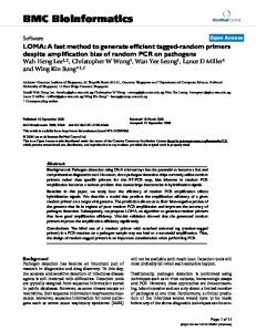
3.1. User Interface to Knowledge Base Editor The knowledge base editor is an extension to the standard graphical Macintosh interface. The extensions concern database design-oriented pallette tools and menus. The dictionary states definitions of attributes, entities and relationships, as well as cross-references between them. The changes to the data dictionary which affect the conceptualdiagram ate automatically reflected in the diagram (e.g. adding attributes to a weak relationship makes it regular). All changes in the diagram are recorded in the dictionary. The dictionary also enforces basic consistency checks (e.g. it does not allow duplicate names or direct connection of entities). The data dictionary has its own multiple-window user interface, The user interface is tailored for easeof use (Figure 2). Picking the tool required, pointing at the desired position on the diagram screen, and clicking the mouse button, is all that is required to createan object. At the time of creation a meaningful namecan be given to the object by simply typing the appropriate name.
Figure2
User
intesface
The connection tools support establishing basic relationship connections. A connection can be made between a relationship oval and an entity rectangle or between two relationship ovals (the latter createsa nestedrelationship set). It is not possible to draw a connection line directly between two entity sets.Onceestablished,the connection remainsfiicd for all editor operations, except for deleting a connected object or explicitly cutting the connection. A designer may define both partial and total membershipof object setsin a relationship. The conectivity (1:l. I:N, M:N) is indicated by means of a somichole,rather than the conventional arrow-head. A databasedesigner may use two classesof abstraction. The aggregation connection tools support the aggregation/decomposition abstraction (black circles). The secondabstraction, generalization, is implemented by meansof black rectanglesattachedto subtypeentity sets. The editor provides an easy iconic way of manipulating objects in the diagram screen. The tools allow the user to relocate object boxes, slide the diagram on the paper, cut. connection lines, delete objects, create and view sub-diagrams (user views). The show/hide tools permit the creation of multiple userviews from a diagram. This feature is particularly useful for scheduling teamwork system development. With this feature, one can create sub-diagrams (sub-schemas), which can be further developed and usedby other teammembers. The lDDK knowledge editor uses seven menu bars. The first one is the standard Apple menu bar and it will not be described here. The File and Edit menu bars adhere to Apple requirements for such menus but are customized to serve editor purposes.The remaining four menu bars @D. Project. Options, and Help) are provided to satisfy some typical knowledge editing functions.
of theknowledgeeditor.
The data dictionary tool provides quick access to any relationship or entity. The object creation tools.allow creation and to someextent modifleation of entities and relationships. AU editing tools (except those that establish connections) can be usedagainst freehand text. To create an object, one of the object editing tools has to be selected.Selecting the entity or relationship tool and clicking anywhere in the diagram screen,createsan entity or relationship set with a default name. The object remains selected to allow a new name to be typed in.
The Data Dictionary @D) menu is aptimaty mechanismof entering the object definitions and the only mechanism of entering the attribute definitions in the data dictionary. From the DD menu, a multi-window editing environment is made available. it provides a means of entering and modifying definitions of attributes and of assigning attributes to entity sets and regular relationship sets(Figure 3). The editor allows adition or deletion of attributes (simple or group) to/from an entity or relationship set. An attribute is added to an object by grabbing and moving it from the box of
- 64 -
:
h Entltu Name: 6ROU~JllfiIWTE
0 connacllulty-second-la
Figure 3 Example
of object&ditioit. 3.2. Declarative Knowlc edge - Entities, Relationships and Attribu’--Its
available attributes to the box of the object content. By moving in the opposite direction, one can remove an attribute from the object. The editor provides for a primary key and up to three candidate keys for an entity set (or a regular relationship set, if applicable). A professional-quality set of documentation of the databasedesign knowledge baseas well as application domain knowledge base can be automatically generatedby the editor. Such documentationis delivered in the form of a ‘ready-to-bind” manual, with a title page,table of contents,etc.
Figure
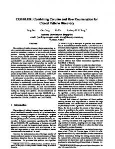
4 Part of ERA representation
of the declarative
The declarative knowledge of IDDK is expressed as a hypersemantic ERA model (Potter and Trueblood, 1988) and implementedas an OFUWLE database.The representationof the declarative knowledge is a multiple-inheritance hierarchy of the objects connected by the is-a and part+/ links (Figure 4). The is-a links denotethe generalization/speciaIizationhierachies.The purr-of links expressthe aggtegation/decompositionhierarchies.
database designknowledge
- 65 -
I
In Figure 4 ovals represent relationships, rectau les entities. The total membership of an entity in a relationsA*upis shown by a solid line that connects the two. A partial membershipis representedby a dotted line. Plain lines are used to express 1 (singular) connectivity. To representM (multiple) connectivity, the semic&k is attached to an M object. Generalization turns a class of objects (usually entities) into a generic object (usually.an entity). The reverse of this is calkd specioization. For imance, in Figure 4 the entity Ob&tClass is regarded as a generic (superrype) entity for the class of entities Entity-Class and Relationship-Class. We use such a generalization to ignore individual differences between subtype entities. A nlationship that mlares a supertypeentity to subtype entities is called a generic relationship. Black rectangles attached to subtype entities are used to denote a generic relationship. They also indicate that subtype The aggregation transforms a relationship between objects (usually entities) into a higher level, aggregate{superset)object. The reverse of aggregation is called decomposition. For instance, in Figure 4 the subset entities Connection-Class, Simple-Entity and Simple-Relationship can be abstractedinto a superset entity Relationship-Class. We can make such an aggregation to ignore details about the subset entities. For example, we want to think about a Relationship-Class without bringing to mind such details as what are the candidate keys, if any, of a relationship. The existence of an aggregation is indicated by black circles attached to an aggregaterelationship. All subsetentities have connectidn lines that end with the black circle. This also represent an upward attribute inheritance mechanism of aggregation(i.e. from subsetentities to a supersetentity). Clearly, there is an important differince between the inheritance mechanisms of aggregation and generalization. Contrary to aggregation, the inheritance of attributes in generalization is downward (top-down). Aggregation and generalization can be applied to composite objects to form aggregatesand generics.The root of the knowledge hierarchy , called DD-Super-Object. is a generic object representing all objects, attributes and connections in the knowledge base.The root must exist in order for the axioms of database design knowledge to be hierarchically defied and satisfied. As an example, a part of the declarative knowledge about objectsand attributesis of the form: Axial 1: There exists an entity with the name E Axiam Axiom Axiom Axian
which is found at the point P on the diagram. 2: There is a connection of type T from relationship R to an entity E. 3:There exists an attribute with the name A. 4: The attribute A has the format F and constraints C. A is found in the entity E. 5: The attribute
3.3. Proctdural Transitions
Knowledge - Database Design and Consistency Enforctments
Current methods and techniques of artificial intelligence and expert database systems do ‘not allow for purely declarative construction and manipulation of complex knowledge bases.In the database design area, the deductive capabilities of the declarative knowledge are liitid to those design aspectsfor which production rules (if-then clauses) can be stated. The procedural knowledge is used to fill the gapsin all theseaspects of the databasedesign process in which extensive calculation, follow-up integrity-enforcement operations, and human intervention are neuled. The models used in the de’&gnare: Business Model, Data Flow Diagrams Model, Entity Model or Entity-Relationship Model, Relational or Network Model, Application Design Model, Design Recovery and ReverseEngineering Model, and a few others. Design process(major input-output transformations): Problem Statement + Strategic Plan -+ Business Modal Business Model + (Document Flows, Implementation Plan, Data Flow Diagram) Data Flow Diagram + (Entity Model, Functions Specs, Entity-Relationship Model) Entity-Relationship Model + Normalized EntityRelationship Model + Relational Logical Model -3 Prototype System Entity-Relationship Model + Network Logical Model Functions Specs + Structure Charts - Screen Painting + Program Generation Logical (Network or Relational) Model + Physical (Network or Relational) Model Application Design Model + Operational System 4 Design Recovery and Reverse Engineering Model
In order to exemplify the procedural aspectof the IDDK knowledge base, suppose that we are creating application domain knowledge (for a specific application).. At the begining of the design (state0), the databasedesign knowledge contains: (1) the declarative database design knowledge (axioms and integrity constraints), and (2) the procedural database design knowledge (the set of allowed operations, add-entity(E), e.g.. add-relationship(R), add_attribute(A), delete-entity(E), Suppose that in a given application design state at the conceptual level, we have already defined the entity e with a group attribute g which in turn contains the attribute s, and a relationship r with the attribute s. In the next step, the designer wants to remove the attribute s. The diagram of the design situation is illustrated in Figure 5.
etc.
The declarative knowledge provides the derivation of not explicitly stored theorems(data) from those stored in axioms. It assuresthe integrity-preserving knowledge basemanipulations and it maintains the consistency of the database design knowledge. It also describesall potentially available operations which may be applied to transform the declarative knowledge, e.g. the specification of pre-conditions to add an attribute to an entity. - 66 -
FigureS Example of anapplicationdesign situation at the c~~epcual level.
. ... To remove the attribute the system uses the procedural knowledge relating to the delete operation. This knowledge contains descriptions of operations and constraints which have operation. The to be satisfied to appIy the Delete-atrribute defmition of the Remove-attribute procedureis asfollows: procedure Remove-attribute(a) begin if Inused (a) then Delete-attribute(a) else begin while g = Group-uses(a) begin if Last-reference(g) then Remove-attribute(g) else Delete-referenceIg,a)r end; while o = Object-uses(a)
m6@dO~ogi6S,S!lcb aStlO~~ZationandabstraCtiOtt, for design refitietnents; * enhancementsto entity-relationship model (e.g.relationship attributes, nestedrelationships, entity roles, generalization, ” aggregation); * knowledge base which captures static and behavioral aspectsof systemdesign; * strong design heuristics to olhninato, at early stages,paths of investigation that have little chanceof success. * various optimization tools to improve databaseperformance (especially on the physical design Level);
Attempt IOdeletes, discover it is used in group g. Discover it is the last attribute in g, so detete g. Anetnpt to delete g, discover it is used in entity e. Remove reference to g frcmt e.
Deletegroupg. {lmpticitly
begin
deletes reference to s). Attempt to delete s, discoverit is still usedin tie reIatkwhip r.
Delete-reference(o,a): end; Delete-attribute(a): end; end.
The internal representation of our diagram (Figure 5) in the design statebeforeRemove-attribute(a) is illustrated in Figure 6.
Delete rcfeencc to sfrom relathhip r.
Delete attrhue s.
Figure 6 The internal
Figure 7 Using procedural knowledge in cbt Remove~arrri6nfe operation.
representation of the designsituation.
The process of removing the attribute s is illustrated diagramatically in Figure 7. The databasedesign methodology that underlies IDDK is process-driven. This means that the design begins with the specifications of user processing requirements. These specifications are then used to validate most intermediate design results. The seminal idea is that the databasesystem should be closely tailored to specific user needs,rather than correspond tc a vaguely understoodconcept of the “nature of data” (expresmi in terms of various data dependencies).Although in lDDK the data dependencies do not drive the design, they are used to validate and enhance some data structuring decisions. The process-driven approach of lDDK has a direct impact on the procedural databasedesign knowledge, as seen in the specific features-: * a methodology extending over the entire life-cycle of a databasesystem; * utilization of techniques intrinsic in data-oriented -67 -
*
*
adherence to ANSI’85 definitions for databaselanguage SQL (relational model) and Network DatabaseLanguage NDL (network model) (Technical Committee X3H2, X3 Secretariat/CBEMA); applicabilty to the design of databases which provide relational user interface on top of network data structures (such as IDMS/B, IDMS/SQL, or BDMS1100). Macintosh workstation graihics, U&and relational DBMS interface; graphical and textual output of databaseschemas (conceptual,logical, physica&versatile reprts; supportfor derivation of database‘progra;ths; redestgn support and significant propagationof design changes.
4. CONCLUSION Due to the popularity and successes of computer-assisted software engineering tools, there is a growing need to provide a foundation for constqtcting a new category of knowledge-based CASEKADE systems.We believe that our work is a step in this direction. We have described in this paper a framework for
intelligent databasedesign and a knowledge base for database design.
MACIASZEK, L-A. (1989): Database Implementation, Prentice-Hall (to appear).
The development of a knowledge base to govern the databasedesign processis a complex problem. The complexity is partly caused by the intrinsic requirement of describing the issuesinvolved by fncansof themselves.This was evident in the paper: The knowledge editor serves not only to support the knowledge acquisition function of the IDDK (meta-datalevel), but it is also a stand-alone tool for entitv-relationshin-attribute modelling (data level). In the latter fun&ion, the to&l is called IDDK:ERA-Editm. is imnlemented in LirrhtsueedCTNfor the Macintoshm and is now available commer&lly:
MICHALSKI, R-S, CARBONELL, J.G. and MITCHELL, T.M. (1983): Mrrchine Lear&g, Tioga Publ.
The bulk of the paper was concernedwith the description of the declarative and procedural databasedesign knowledge. A large part of the knowledge base has been implementedin a prototype form as an Oracle database and it is being experimentally used to drive existing tools of the Intelligent DatabaseDesign Kit. At the time of writing, IDDKERA-EditTM is integrated at the “front-end” with IDDKrDFD-Editm (data flow diagramming tool) and at the “back-end” with IDDKLRzh;zy (converter from ERA, design to relational database To achieve a full implementation of the knowledge base, further researchand developmentwork is neededto interface the knowledge base with the inference engine and knowledge acquisition methods. Tn particular, continuing work is being done on aspectsof knowledge representation both in database design and application domain areas, including aspects of incomplete specification and non-monotonfc logic. Some extensions and changesto the knowledge baseschemaate likely to be enforced by the developmentof successiveIDDK tools.
REFERENCES BRODIB, M.L. and MYLOPOULOS, J. (eds.) (1986): On Knowledge 3aFe ManagementSystems.Springer-Verlag. CHEN, P.P-S. (1976): The Entity-Relationship Model - Toward ;6Jnificd View of Data, ACM Trans. Database Syst., 1, pp.9DOLK, D.R. and KIRSCH 11, R.A. (1987): A Relational Information Resource Dictionary System, Comm. ofthe ACM, 1, pp.48-61. FROST, R.A. (1986): Introduction Systems,Collins
to Knowledge Base
GOLDFJNE. A. (1985): The Information ResourceDictionary System, Proc. 4th Int. Conf. on E-R Approach, Chicago, USA, IDDK (1988): IDDK:ERA-Edit lDDK Software, p.33.
Fundamentals, Version 1.0,
KELLER; R. (1987): Expert SystemTechnology, Development and Application, Yourdon PressComputing Series MACIASZEK, L.A. STAFFORD, G.J. HAYWARD, J.J. HAYWARD, M.R. and KRAV, S.I. (1988c): A CADE Tool to Derive a Relational Database Structure from an Enhanced Conceptual Design, Proceedings Australian Software Engineering Conference - ASWEC’88, Canberra, Australia, pp.137-154.
- 68 -
Design
and
POTTER, W.D. and TRUEBLOOD. R.P. (1988): Traditional, Semantic, and Hyper-Semantic Approaches to Data Modeling, Comp., June, pp.53-63. SMITH, J.M. and SMITH, D.C.P. (1977): Database Abstractions: Aggregation and Generalization, ACM Trans. Database Syst., 2, pp.105133. STACHOWITZ, R.A. (1985): A Formal Framework for Describing and Classifying Semantic Data Models, Inform. Syst., 1, pp.77-96. SU, S.Y.W. and RASCHID, L. (1985): Incorporating Knowledge Rules in a Semantic Data Model: An Approach to Integrated Knowledge Management, Artificial Intelligence Applications, The Engineering of Knowledge-Based Systems, Proc. 2nd Conf., ed. C.R.Weisbin, IEEE CS Press/NorthHolland, pp.250-256.