A Low-Noise Microsensor Amplifier with Automatic Gain Control System Jun-Hong Weng
Chong-Jng Yu
Ching-Yuan Yang
Peng-Chang Yang
Department of Electrical Engineering, National Chung Hsing University, Taichung , Taiwan
[email protected]
Department of Electronics Engineering, Feng Chia University, Taichung , Taiwan
Department of Electrical Engineering, National Chung Hsing University, Taichung , Taiwan
[email protected]
Department of Electronics Engineering, Feng Chia University, Taichung , Taiwan
[email protected]
[email protected]
Abstract— A 0.35-µm CMOS instrumentation amplifier with automatic gain control (AGC) system for the sensor interfaces is presented in this paper. The circuitry employs a chopper stabilization technique to significantly reduce the lowfrequency noise and DC offset. The AGC is used in the system where the amplitude of an incoming signal can vary over a wide dynamic range. The AGC circuit provides relatively constant output amplitude in spite of the sensitivity of the sensor due to the parameter variations. Furthermore, the whole system has been kept fully differential operation in order to get higher immunity to environmental noise of supply voltages, clock feedthrough, charge injection, even harmonic distortion, etc. It features a gain of 53±17 dB with 25-kHz bandwidth. The equivalent input noise is about 1.13 µVpp at 98.2-kHz chopper frequency.
I. INTRODUCTION The evolution of IC processing technologies in the last decade have not only resulted in vastly improving performance of scaled-down digital VLSI circuits, but also worried rapid expanding of silicon-based integrated microsensors. A well-known trend in recent development is to integrate the micro-sensor structure with an electronic circuit in the same processing technology to enhance the performance by on-chip conditioning circuitry. Furthermore, a combination of microsensor and circuits with a standard CMOS technology makes the resulting microsystem products more competitive in price by reducing the complexity and cost in packaging and by tapping the strong manufacturing base of the IC technologies, which have perfected themselves in low-cost mass production. In other words, it makes possible the realization of complete systemson-a-chip. The aim of this work is to design and realize a CMOS instrumentation amplifier with automatic gain control (AGC) system. In many applications, such as sensor interfaces, the overall performance of the system is limited by the offset and noise of the input amplifier. In this paper we present a low-
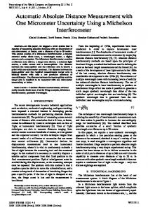
Fig. 1. Block diagram of microsensor front end system.
noise fully-differential chopped preamplifier, which is capable of reducing 1/f noise and offset by chopping up to 120 kHz. In order to minimize the residual offset due to the chopped clock of the input modulator, the 2nd-order Gm-C biquad filter is added. Furthermore, joined AGC circuit to yield the same output volume of the microphone will be changeless differ from any human voice. In addition, it must also meet the following specifications: low-supply voltage and low-power consumption, high power supply rejection ratio (PSRR), and high common-mode rejection ratio (CMRR). II.
CHOPPER STABILIZATION ARCHITECTURE
In contrast to the switched capacitor auto-zero techniques that are methods of reducing flicker noise and offset based on sampling [1], chopper stabilization is a modulation technique that also can be employed to reduce the effects of opamp imperfections including noise (mainly flicker and thermal noise) and the input-referred DC offset.
Fig. 3 Block scheme of 2nd–order bandpass filter.
Fig. 2 Low-noise rail-to-rail preamplifier.
As can be seen, chopping is the only way which reduces 1/f noise and offset without modifying the baseband white noise like in the sampling case [2-4]. Fig. 1 shows the frontend amplifier system for the microsensor. The system is composed of an input modulator, a low-noise rail-to-rail preamplifier, a second-order bandpass filter (BP), an output modulator, a bandpass-based matched oscillator and an AGC component. Note that the signal path throughout the whole system has been kept fully differential operation in order to get higher immunity to environmental noise. The on-chip oscillator consists of high-Q BP, similar to that in the front-end blocks, connected in a positivefeedback loop with a hard limiter [5]. The output of the BP will be a sine wave whose frequency is equal to the center frequency of the filter, fchop. The sine-wave signal is fed to the limiter, which produces at its output a square wave whose levels are full-swing and whose frequency is fchop. The square wave in turn is fed to the BP, which filters out the harmonics and provides a sinusoidal output at the fundamental frequency fchop. The generated full-swing square waves are also fed to modulate and demodulate the desired signals at a chopper frequency, fchop. III.
CIRCUIT DESCRIPTION
A. Rail-to-rail preamplifier In order to improve signal dynamic range and common mode input range under a 1.8-V supply voltage, it is necessary to use a rail-to-rail input stage. The circuit is shown in Fig. 2 [6], which is constructed from a rail-to-rail OTA followed by a transimpedance stage. The bandwidth of the amplifier should be high enough to ensure that little gain and phase distortion (loading effect) is introduced to the system. The rail-to-rail input stage is realized by combining two folded-cascode amplifiers with NMOS and PMOS input differential pairs such that when one is disable for either high or low common-mode (CM) level input, the other is still active. An important concern, however, is the variation of the overall transconductance (Gm) of the two pair as the CM level of the input signal changes. To provide constant Gm, we use two maximum current select (MCS) circuits, which are made of transistors of M9 to M20. The MCS circuit
Fig. 4 (a) Oscillator based on BP. a. Proposed nonlinear resistor, (b) conventional limiter, and (c) proposed limiter and its i/v characteristics.
compares two input currents, e.g. in1 and ip2, that come from N-pair and P-pair input stages respectively, and output the maximum one. This is because that either current source (M9, M10) or current sink (M11, M12) are introduced into triode region by the two different input currents, and do not act as a constant current source anymore. That means one of the two current sources will work as a load. Consequently, the Gm of the OTA is universal constant. B. Bandpass filter & matched oscillator The block scheme of a fully-differential 2nd-order Gm-C BP is depicted in Fig. 3. The basic building block is an integrator including a transconductor and a capacitor. To link up the matched oscillator, the BP filter is aimed at reducing the residual offset stems from the charge injection of the input modulator. The BP filter with center frequency (fc) similar to the clock signal (fchop) used to operate the switches is the top priority for low residual offset. Thus we can use an on-chip oscillator which uses the same BP structure to achieve fc = fchop, shown in Fig. 4(a). [7] This is a BP-based matched oscillator. In conventional discrete circuit (Fig. 4(b)), the nonlinear amplitude limiter function is implemented by two parallel diodes but it should be replaced by Fig. 4(c). If Vr < E then Vg is “Low” and transistor Mr is in cutoff (ir = 0). If Vr > E, Vg becomes “High” and Mr is on and capable of driving a large current. With regard to upper PMOS, it has similar principle of operation. Since the performance of the comparator is not critical, a simple differential input to a single-ended output amplifier can be used.
C. Automatic gain control system The AGC loop [8], shown in Fig. 5(a), consists of a variable gain amplifier (VGA), a peak detector, a Gm-C integrator and a level shifting network. The VGA is constructed as a differential inverting amplifier with a gain controlled by tuning the two differential variable resistors. The major benefit of this structure is that the gain of the VGA is almost independent of process parameter drift and thus immune to the substrate coupling. The peak detector, shown in Fig. 5(b), operates as follows. When the voltage level of either input node, Vop and Von, is lower than Vpk, the difference ∆V is sensed by the corresponding amplifiers, which composed by M1-M6 and M7-M12, and a current (Gm*∆V−Io) is generated to discharge the capacitor C toward low level. When both inputs are above Vpk, C is charged by the current Io toward VDD. Therefore, at the steady state, Vpk ≈ min (Vop,min, Von,min). Vpk is then compared to AGC reference voltage, VTH, and the difference is used to generate control voltage by level shifter. Finally, in order to obtain proper control voltage for the two differential variable resistors, a level shifting network formed by four PMOS source followers are used, which tunes (Vc3−Vc2) and (Vc4−Vc1) in the opposite directions while keeping (Vc3+Vc2) and (Vc4+Vc1) constant. In this way, the equivalent input resistance will be fixed, and so does the gain of the preceding stage. The dB-linear gain control characteristic of the VGA is an essential requirement for a constant loop settling time. Fig. 6 shows the simulated VGA gain as a function of the control voltage.
Fig. 6 VGA gain as a function of the control voltage.
IV.
EXPERIMENTAL RESULTS
To verify the performance of the microsensor amplifier as previously described, the proposed circuit has been fabricated in a 0.35-µm double-poly N-well CMOS technology. Fig. 7 shows the microphotograph of the test chip. The measured waveforms of the AGC are shown in Fig. 8. At the output, the spectrum analyzer measures the noise of the amplifier amplified with 40 dB in a bandwidth of about 25 kHz which is exactly the bandwidth of the low pass filter. Its transfer function is shown in Fig. 9. Note that the added instrumentation amplifier let the open loop gain up to 80 dB. Fig. 10 shows the low frequency noise measurement result. We can find that chopping from 0 Hz to 98 kHz the flicker noise can be removed from 384 µVp-p to 1.13 µVp-p. Table I summarizes the overall specifications of the sense amplifier.
(a)
Fig. 7. Test-chip microphotograph.
(b) Fig. 5. (a) AGC loop, and (b) peak detector.
Fig. 8 Measured waveforms of AGC for 10-kz input. (a) Input and (b) output waveforms.
wide common mode input range and wide gain range are realized by using a wide-swing constant-Gm bias circuit, a rail-to-rail low noise preamplifier and an AGC. The high CMRR and PSRR are obtained by the fully differential structure and the use of a cascode structure. The 2nd–order Gm-C BP, combined the on-chip oscillator, is implemented to reduce the residual offset due to the clock feedthrough of the input modulator. ACKNOWLEDGMENT The authors would like to thank the National Science Council of Taiwan for the financial support and the Chip Implementation Center (CIC) for the infrastructure support. REFERENCES [1]
Fig. 9 Measured transfer curve of chopper amplifier
[2]
[3]
[4]
[5] [6] (a) (b) Fig. 10 Low-frequency noise measurement: (a) fchop = 0 Hz, and (b) fchop = 98 kHz.
[7]
TABL I: PERFORMANCE SUMMARY OF THETEST CHIP Technology
0.35-µm 2P4M CMOS
Power Supply
1.8 V
Common mode input range
0 ~ 1.8 V
Chopper Frequency
98.2 kHz
Gain
53 dB+/-17 dB
AGC
Max:17dB Min:-16.6 dB
CMRR
77dB @ fchop
PSRR+
57 dB @ fchop
PSRR -
43 dB @ fchop
Equivalent input noise
1.13 ~ 384 µVp-p
Equivalent input DC offset
~36.8 µV
Power Consumption
< 1 mW
V. CONCLUSION The chopper stabilization technique is adopted to reduce flicker noise and DC offset in this work. Furthermore, the
[8]
C.C. Enz and G.C. Temes, “Circuit techniques for reducing the effects of op-amp imperfections: autozeroing, correlated double sampling, and chopper stabilization,” Proceedings of the IEEE, vol. 84, pp.1584-1614, Nov. 1996. C.C. Enz, E.A. Vittoz and F. Krummenacher, “A CMOS chopper amplifier,” IEEE J. Solid-State Circuits, vol. 22 , pp. 335-342, Jun. 1987. C. Menolfi and Qiuting Huang, “A low-noise CMOS instrumentation amplifier for thermoelectric infrared detectors,” IEEE J. Solid-State Circuits, vol. 32 , pp. 968-976, July 1997. C. Menolfi and Qiuting Huang, “A Fully Integrated, Untrimmed CMOS Instrumentation Amplifier with Submicrovolt Offset,” IEEE J. Solid-State Circuits, vol. 34 , pp. 415-420, July 1997. A. S. Sedra and K. C. Smith, Chop. 11 of Microelectronic Circuits, Oxford Univ. Press, 1998. Hu Yamu and M. Sawan, “CMOS front-end amplifier dedicated to monitor very low amplitude signal from implantable sensors,” IEEE CNF. Circuits and Systems, 2000. Proceedings of the 43rd IEEE Midwest Symposium on, vol. 1, pp. 298-301, Aug. 2000. B. Linares-Barranco, A. Rodriguez-Vazquez, E. Sanchez-Sinencio and J.L. Huertas, “10 MHz CMOS OTA-C voltage-controlled quadrature oscillator,” IEEE J. Electronics Letters , vol. 25, Issue 12, pp. 765-767 ,June 1989. S.A. Sanielevici, K.R. Cioffi, B. Ahrari, P.S. Stephenson, D.L. Skoglund and M. Zargari, “A 900-MHz transceiver chipset for twoway paging applications,” IEEE J. Solid-State Circuits, vol. 33, pp. 2160-2168, Dec. 1998.