is relayed by the terminal through the radio link to the stationary radio station, which .... the bottom sub-layer of the DDX layer, called the Color Frame Bu er code, or CFB ...... Master's thesis, Massachusetts Institute of Technology, August 1995.
A Low Power, Low Bandwidth Protocol for Remote Wireless Terminals George Hadjiyiannis Department of EECS MIT, Cambridge
Anantha Chandrakasan Department of EECS MIT, Cambridge
Abstract
Srinivas Devadas Department of EECS MIT, Cambridge
We present a low bandwidth protocol for wireless multi-media terminals targeted towards low power consumption on the terminal side. With the widespread use of portable computing devices, low power has become a major design criterion. One way of minimizing power consumption is to perform all tasks, other than managing hardware for the display and input, on a stationary workstation and exchange information between that workstation and the portable terminal via a wireless link. A protocol for such a system that emphasizes low bandwidth and low power requirements is presented herein. Such a protocol should address the issue of noisy wireless channels. We describe error correction and retransmission methods capable of dealing with burst error noise up to BERs of 10?3. The nal average bandwidth required is 140Kbits/sec for 8-bit color applications.
1
1 Introduction Recent years have seen a dramatic increase in the demand for computational resources. The major trend in recent years has been for users to demand easier access to computers. Personal workstations have not fully satis ed this need and portable computing has become a focus of considerable attention. Various researchers (e.g., Mark Weiser at Xerox PARC [1]), intend to take this even further until computers are so common place and so much in tune with human needs that their users are not even aware of them. This notion has been termed \ubiquitous computing"[1]. For the moment, portable computing is the only manifestation of ubiquitous computing that has gained any commercial success. Unlike the Xerox PARC portable terminals, portable computing has centered mostly around self-contained computers that do not require an external source of power or network connection. These devices, while generally inferior to the standard stationary personal computers, o�er access to computational resources virtually at all times and places. They do, however, su�er from two serious problems (other than their inferior computational power): They are generally heavy due to sizable rechargable batteries, and they cannot be used for extended periods of time away from a power supply (generally about 3 hours). Both these problems can be alleviated by reducing the power consumption. While power consumption is becoming a serious concern for the designers of the new breed of ultra-fast microprocessors, it is the eld of portable computing that best motivates research into low-power dissipative technology.
1.1 Factors A�ecting Power Consumption The easiest way of reducing the power consumption of any computing device is to reduce the amount of computation it performs. Power consumption is proportional to C � V 2 � f where C is the e�ective capacitance switched, V is the voltage at which the circuitry operates, and f is the switching frequency. Reducing power consumption involves reducing any or all of the above factors. Reducing C means reducing the computational units active at any given time 1 . This is contrary to the normal goal of performing as much as possible in parallel for reasons of speed. Even if one were to only use one computational unit at any given time, since now the task takes correspondingly longer, the total energy consumed remains the same. In short, the only reasonable For the purposes of this discussion we assume a constant technology and constant design methodology. If nothing else, one could easily reduce C by moving to a more aggressive process. 1
2
way of reducing the capacitance switched is by deferring some of the computation to other resources and thus eliminating some of these computational units2 . Reducing f reduces the rate at which these units operate. Reducing V increases propagation delays which forces a reduction in maximum f [2]. Therefore, any attempt to reduce the power of a computational device by any signi cant amount3 will result in lower throughput from that device.
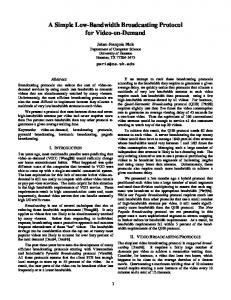
1.2 The Stationary Cycle Server Model An interesting way to work around the power/throughput tradeo� has been used by both the Xerox PARC group and the InfoPad group at Berkeley [3, 2]. The portable computer (hereafter called the terminal) can do just enough work to manage the input and output devices and defer all other computation to a separate cycle server (hereafter called the stationary cycle server or just cycle server for short). The terminal and the cycle server can be connected in such a fashion as to allow the terminal to transmit all input to the cycle server and the cycle server to transmit all output back. If the connection method is wireless, then the terminal becomes e�ectively a portable computer (see Figure 1). Since the cycle server is stationary, it can have an external power source and the only power consumption that the designer needs to be concerned with is that of the terminal. This becomes an easier task since the terminal can be designed to perform the minimal amount of computation necessary to manage the input and output devices. Nonetheless, to the user, the terminal appears to have all the processing power of the stationary cycle server. Under this scheme, all the applications run on the cycle server while the display and input device management programs (e.g., a window server) run on the terminal. Input from the devices is relayed by the terminal through the radio link to the stationary radio station, which then places it on the network. From there, it nds its way to one of the stationary cycle servers, which processes the input and feeds it to the applications. The applications then inform the cycle server of any impending output (e.g., updates to the display), which is then put in the right format and placed it on the network. The stationary radio stations take the properly formatted output and relay it over the radio link to the appropriate terminal. Finally, the terminal decodes the message and performs the appropriate updates or output actions. Both the InfoPad and the Xerox PARC Pads work on this principle. The Xerox PARC Pads Note, however, that one can opt to use more computational units to o�set the reduction in speed caused by reducing the voltage V . This can result in a net decrease in power consumption. 3 For the scope of the above statement, a signi cant amount would be something close to one order of magnitude. 2
3
are not much lower in power consumption than normal laptops and the main reason why they use the cycle server model is to create a uniform distributed computing environment. The InfoPad uses the cycle server model speci cally for reducing power consumption and, with the core chip-set consuming no more than 5mW, it is probably the most successful attempt to do so. 4
1.3 The InfoPad Protocol The InfoPad is based on the X-protocol. Rather than running a complete X-window server on the terminal, a new protocol was designed that allowed most of the X-window server tasks to be moved to the cycle server. Thus, the raw pen events are relayed from the InfoPad terminal to the cycle server over the radio link, where they are processed by a modi ed X-window server. The X-server processes the input events as if they came from a local keyboard and mouse and then generates events for the applications. The applications process any input they receive, and send any necessary output requests to the X-server (just like they would if the X-server was to display it on the local screen). The X-server calculates the necessary updates to the display, packs that information through a special protocol, and relays it over to the terminal. Finally, the terminal unpacks that information and updates the screen accordingly (see Figure 2). One of the main design issues was the nature of the protocol to be used between the X-server that was running on the cycle server, and the terminal itself. Since the main design goal was to make the power consumption of the terminal as small as possible, the protocol was designed such that the hardware requirements on the terminal side were as simple and as minimal as possible. For the rst generation of terminals, it was decided to send the full display updates as a series of bits for every pixel that had to be modi ed on the display. Later generations used enhanced protocols that had lower bandwidth requirements. Note that this description only applies to the text and graphics display. It does not cover the video portion of the output, which used a di�erent protocol to transmit compressed video. We call protocols like the rst generation InfoPad protocol \computationally cheap" since they try to minimize the computation performed on the terminal. Because of the computationally cheap protocol that was used, there was very little processing to be done after a packet for the graphics display was received. That makes the hardware small and fast and the InfoPad group took advantage of this by casting all processing to silicon. Given that the best way of reducing power For comparison's sake, that is not much more than the power consumed by one of the LEDs on a standard keyboard or portable. 4
4
is reducing the supply voltage which causes a system slowdown[2], the fact that the protocol could be decoded in hardware was a particularly important feature. However, the computationally cheap protocol turned out to have some side e�ects. To begin with, the fact that all the bits that were updated in the frame bu�er had to be transmitted to the terminal caused a serious bandwidth problem. For example, some applications would draw text by copying the pixels for the characters to the screen. While this can be bad in terms of bandwidth requirements even in monochrome applications, the problem would be 8 times more severe for 8-bit color displays. Thus a computationally cheap protocol could cause two problems:
� It would require large bandwidths on the downlink that sends the data from the cycle server to the terminal. Also it means that when large portions of the display change (such as the example of putting a large amount of text on the screen), the latency of transferring such a large amount of data becomes the dominant portion of the response time of the whole system.
� Since the implementation of the protocol is now in hardware, it is particularly in exible,
requiring the design and fabrication of new components for every change in protocol that needs to be made. While a fully general approach might not be necessary, some software
exibility would be desirable.
1.4 Our Approach This paper represents our e�ort to extend the work of the InfoPad group. The basic premise of a low power terminal achieved by using the stationary cycle server model is still the goal, but having the bene t of all the data collected by the InfoPad group, we decided to use a di�erent approach to the problem. To begin with, we decided to replace the InfoPad's hardwired protocol with a general-purpose processor enhanced with application speci c optimizations, at the expense of higher hardware complexity and larger power consumption. Thus, the terminal and its protocol would become relatively exible, allowing us to make use of better algorithms, new extensions to the X-server, and to make additions and modi cations to the protocol at will. Then we decided to employ a more computationally expensive protocol which would reduce the bandwidth requirements and alleviate some of the problems associated with the high bandwidth, while at the same time allow the use of color. This enhanced protocol was the rst step in the project and is the subject of this paper. 5
2 The Communication Protocol As described in section 1.3, the main reason for moving to a new protocol was to reduce the amount of information that has to be sent on the downlink to the terminal. By giving the protocol the notion of higher level elements (for example, rectangles, polygons, lines etc.), it is possible to create a protocol that requires much less information to perform the same activities. Consider again the example of section 1.3. If the protocol had a notion of what a text character is, one would only need to send a command that identi es the character, its position, and the color to which it should be drawn. We decided to give the protocol the notion of such higher level elements to reduce the bandwidth requirements. We also decided to use color, therefore the protocol had to work for 8-bit pseudo-color frame bu�ers with a 640 � 480 resolution.
2.1 The Raw Graphics Protocol The rst step in developing a protocol was to come up with the exact type of requests that would be necessary, and the information that these requests would require in order to allow the terminal to reproduce the display that the X-server is trying to build. Obviously, a big part of this task is simply deciding which higher level elements (and operations on such elements) would be the best to include in the nal protocol. This set of requests, elements and operations forms what we call the Raw Graphics Protocol. Given this protocol, it would be possible to make a perfectly functioning terminal that would operate with no errors in the absence of noise. Just like the InfoPad and the Xerox PARC Pads, we decided to base our protocol on the X-window system.
2.1.1 The Partitioning Issue The X-server is built with a particularly modular structure that consists of 3 main modules (see Figure 3): On the top level is the DIX layer, or Device Independent layer, and below that are the Operating System layer or OS, and the DDX layer or Device Dependent layer. Each layer consists of sub-layers that exchange information with each other. At the top of the DIX layer is the Transport layer that receives requests from applications. It then feeds these requests to the lower sub-layer of the DIX layer, the Screen functions that determine where the request information should be sent next5 . The Screen functions then pass the request information to the top sub-layer of the DDX layer, a set of functions called the Graphics Context Operations (or GC-ops for short). 5
Each X-server can handle multiple screens. This sub-layer decides which screen each request is meant for.
6
These functions decide how to best go about servicing the request and are responsible for most optimization procedures inside the X-server. These functions then pass the request information to the bottom sub-layer of the DDX layer, called the Color Frame Bu�er code, or CFB module for short. Finally, the CFB layer changes the appropriate pixels in the frame-bu�er to actually service the request. The OS layer acts as an interface between the rest of the X-server layers and the Operating System of the machine. The memory allocation operators, for example, are part of the OS layer. A communication protocol for the terminal can be implemented by partitioning the X-server between any two of the above layers and intercepting the communication between them, to relay that information to the terminal. By reproducing all the layers below the partition on the terminal side, one can reproduce all the actions of the X-server while servicing the request, and therefore one can reproduce the nal display (see Figure 4). That, of course, poses the question of where the partition should be placed. Note that the partition does not necessarily have to lie on sublayer boundaries6 . It is also possible (and in fact necessary for optimization reasons) to place the partition at di�erent levels for di�erent parts of the code. Generally, levels that are higher up have access to more of the basic elements (see section 2.1.3) than levels that are lower. However, by placing the partition lower, one can simplify the protocol as well as avoid performing the work of the higher layers on the terminal. Section 2.1.2 explains why avoiding the work of the higher layers is particularly important in maintaining low power consumption. On one extreme, the partition could be placed on top of the Transport layer. E�ectively, this means running the complete X-server on the terminal and running only the applications on the cycle server. This is the approach that was used by the Xerox PARC Pads. This would make available to the protocol all the information that could possibly be available. The bandwidth required for the downlink would be small since all requests would be using higher level elements, and would have available to them all the X-server state. On the other hand, this would place very heavy demands on the terminal hardware (the memory to store said state being a major concern). On the other extreme, we could place the partition right below the CFB sub-layer and intercept the communication between it and the frame-bu�er. Since the communication between the CFB sub-layer and the frame bu�er consists of the values of the individual pixels, this is e�ectively the In fact, despite the modular structure of the X-server, the boundaries between sub-layers are not all that clear. Only the boundaries between layers are. 6
7
same as the rst generation InfoPad protocol. It has very minimal terminal hardware requirements but su�ers from high bandwidth requirements. For the purposes of the current protocol we decided to place the partition at an intermediate point. While it is true that levels higher than the CFB sub-layer have access to more elements than the CFB layer7, the lower levels of the CFB sub-layer have access to most elements that take part in the actual drawing operations. We decided to place the partition within the CFB layer, immediately above the routines that actually perform the drawing operations in the frame bu�er (see Figure 4). This lower portion of the CFB sub-layer has all the basic notions of geometric objects that might be drawn on the screen, but lacks the notion of all other elements (such as the notion of windows, for example). For most drawing operations, this means that various pieces of information about higher level elements such as windows, have to be transmitted every time (for example the position and clip-region8 of a window). Generally, this overhead is not signi cant enough to warrant the extra complexity of a higher level. For some parts of the code (mainly the portions of the CFB code that handle text) we had to place the partition in the higher levels of the CFB sub-layer, since it would provide us with a substantial bandwidth advantage.
2.1.2 Low Power Issues The main tradeo� in designing the protocol is between bandwidth and computational cost. The main reason why computational cost needs to be kept under control is that it a�ects the nal power consumption of the terminal hardware. There are three major parameters that are dictated by the computational cost which a�ect the terminal hardware power consumption:
Number of Tasks The more computationally expensive the protocol, the more the throughput required, hence the higher the power consumption.
Memory Requirement It is necessary to keep the memory requirements of the terminal to a minimum [4]. Therefore, both the size of the code that will need to run on the terminal hardware, and the amount of state it needs to save, must be kept minimal. Both sizes tend to be smaller for computationally cheap protocols.
The Screen information is such an element. The clip-region is the portion of the window that is actually visible at any given time. Parts of the window might be obscured by other windows. 7
8
8
Better Mapping to Hardware If the protocol is particularly simple, with most operations being
of the same type, then there is a greater opportunity for architectural optimizations to the hardware. Such architectural optimizations allow a reduction in clock rate (which allows a reduction in voltage supply as well) thus providing very attractive power savings.
2.1.3 The Element Types and Operations Once the location of the partition in the X-server was determined, deriving the protocol requests (and hence the element types and operations) was a simple matter of determining what information needed to be relayed to the terminal to reproduce the drawing actions of the X-server. E�ectively, all the drawing routines had to be intercepted to make sure that any operations that a�ect the display are reproduced on the terminal side. Since the partition was placed right above the drawing routines, it was generally unnecessary to save any state for longer than a single request. All the information needed by each drawing routine could be relayed to the terminal for each request. The only exception to the above rule was the cacheing of fonts which is explained later in this section. Here is a listing of the basic elements that the protocol is aware of:
Boxes These are rectangles and form the basis of many of the drawing operations. They are used
both as drawing primitives (e.g. the background of a window is drawn as a rectangle of a given color) and as control information for the processing of other elements (e.g. regions are made up of a list of boxes).
Lines The X protocol de nes lines of varying widths and styles. The drawing routines (and, subsequently, our communication protocol) follow the X protocol de nitions of these blindly. The only exception is zero-width lines which can be drawn by a more e�cient algorithm and therefore have their own request identi er.
Arcs The same comments that apply to lines also apply to arcs. Ellipses This includes circles. The same comments that apply to lines and arcs also apply to ellipses.
Chords These are portions of an ellipse. Again, the communication protocol follows the de nitions of the X protocol for chords.
Pixmaps These are pictures in a standard format. They can have varying depths (roughly equivalent to bits-per pixel) but applications typically use 1 and 8. Depth 1 pixmaps are also called 9
bitmaps. Pixmaps can be used both as drawing primitives (e.g. by copying the pixmap to a portion of the screen) and as control information for other requests (e.g. as tiles and stipples).
Regions These are lists of boxes that de ne a certain portion of the screen. They are generally used as clip regions to restrict other drawing operations to the visible portions of a window.
Text Strings Again, the X protocol speci cations are followed blindly for these except in the case of image text which are optimized. It was decided to intercept text operations at a higher level than the drawing routines since that is where the string and font information was available.
Fonts The X-server actually creates the fonts { they are simply transmitted to the terminal when
necessary. This allows the terminal to use any fonts that the X-server has access to. Since fonts are particularly large structures and their use exhibits a lot of temporal and spatial locality, they are cached. The font cache is the only state that transcends request boundaries (i.e. lasts for more than a single request). The cache size is variable and the protocol can accommodate cache sizes as large as 256 fonts. A much smaller size (on the order of 6 entries) is generally adequate for most types of use. When the cache is full, cache entries are overwritten using a Least-Recently Used (LRU) criterion.
Colormap Entries These are the entries in the table (colormap) that translate the 8-bit value of a pixel to an actual RGB value that can be displayed by the hardware.
The following operations are available to the communication protocol:
Basic X protocol operations [5] The X protocol de nes 16 operations by which the new drawing
primitive can be combined with the existing contents of the frame-bu�er to yield the nal image. All 16 are supported by the communication protocol. Some of them are optimized and have their own request identi ers (e.g., the Copy request which overwrites the old contents of the frame-bu�er and therefore does not need to read the frame-bu�er { only write to it).
Stippling Operations These are operations that use a bitmap as a mask in order to only a�ect certain portions of the image.
Clipping Operations These are operations that restrict the basic drawing operation to a particular region (that might contain multiple boxes).
Input Operations Five requests are reserved to allow the transmission of user input (e.g. from a mouse or keyboard):
10
Pointer Motion The user has moved the main pointer (e.g. a mouse or pen) to the new location mentioned in the request.
Button Press The named button on the main pointer was pressed. Button Release The named button on the main pointer was released. Key Press The named key on the keyboard was pressed. Key Release The named key on the keyboard was released. The above set of elements and operations forms what we call the Raw Graphics Protocol (the fully functional protocol before error correction, detection and retransmission).
2.2 Error Correction, Detection And Retransmission The raw graphics protocol is all that is necessary to allow the terminal to work in the absence of any noise. Wireless communication channels, however, are notorious for containing strong noise sources. An unfortunate consequence of making a protocol out of higher level primitives is that its noise tolerance decreases dramatically. In the InfoPad protocol, most of the data represents pixels on the screen. If any of that data gets corrupted, the end result will be that some pixels on the screen will have the wrong color. For our raw graphics protocol, however, a very substantial fraction of the data is control information that dictates the request type, the clip regions, the locations of the primitives, etc. If any of that data gets corrupted, the results could be disastrous. The primitive might be drawn to the wrong place on the screen, it might be clipped severely or even the wrong request might be detected at the terminal side with completely unpredictable results. The raw graphics protocol is therefore particularly ill-equipped to deal with noise. One possible solution would be to wrap the data in an error detecting code (e.g., a CRC) and then retransmit any requests that were corrupted. However, one of our design goals was to make the protocol work relatively well9 with Bit Error Rates (BER for short) as high as 10?3.10 Given the size of some of the requests, the above scheme was likely to result in an unacceptably large number of retransmissions since a large number of requests would have at least one bit corrupted. A It is not possible to guarantee how well any wireless system will operate in the presence of noise. In the worst possible case, a large object could be obscuring the transmitter, in which case, irrespective of the protocol, it will be impossible for the terminal to receive any requests whatsoever. 10 Both the expected noise characteristics and the noise produced by our emulator environment have a large content of burst noise which is a lot harder to overcome than simple random noise. 9
11
better approach would be to use a code that can actually correct many of the errors, thus avoiding the need for retransmission in most cases.
2.2.1 The RS(15,9,7) Error Correcting Code A number of error correcting codes were explored for use in the protocol. The nal choice was a Reed-Solomon code that works on 4-bit symbols, encodes 9 symbols to 15, and detects and corrects 3 simultaneous errors[6, 7]. The main advantages of this code that lead to its nal use are listed below:
Immunity to Burst Mode Noise It requires bursts of noise at least as long as 10 bits before
the code will fail to correct the errors. After two-way interleaving11 (the interleaving that was used for our protocol), the shortest burst that will be uncorrectable is 22 bits.
Large Error Detection Capacity After two-way interleaving, the shortest burst error that may be undetectable by this code is 22 bits. As is described in the next section, error detection capability proved to be particularly important and it was in fact necessary to enhance the error detection process by the use of a CRC.
Small Size The code is relatively small, each codeword having 15 symbols (60 bits). This is important for two reasons:
1. The whole encoding process can be cast into hardware making it much more e�cient both in terms of speed and in terms of power. 2. When the number of bytes does not exactly t into an integer number of codewords, it has to be rounded up by padding thus creating an overhead on bandwidth.
2.2.2 The Two-Level Encoding Scheme Our preliminary results from the raw graphics protocol (see section 3.2) indicated that the largest amount of bandwidth was consumed by pixmaps being sent as raw data for copying onto the display (e.g., little icons on applications or large images in image viewers). Since these consisted of individual pixel data rather than control information, the worst possible outcome of such data being corrupted would be some pixels being displayed in the wrong color. Experience with the N-way interleaving means that instead of sending all the symbols for each packet in a string, you send the rst of each of N packets rst, then the second symbol of each packet and so on. 11
12
InfoPad showed that, while such errors create a less pleasing display to the user, it is nonetheless acceptable [3, 4]. There was no reason to incur the large overhead of error correction just to protect the pixel data. We decided to use the same, two-level encoding scheme that the InfoPad project used. We arranged the packing of information so that all the control information comes rst and the pixel data (if any)12 comes last. The error correction system only corrects the rst portion of the message which contains the control information. The number of bytes that are encoded is stored in the header of each request so that the other side knows how to re-assemble the message. Note that the unencoded data is never retransmitted unless the header could not be read (see section 2.2.3).
2.2.3 Error Detection and Retransmission Despite the large error correcting capacity of the Reed-Solomon code, measurements with our emulation environment showed that there were a large number of errors that the code could not correct (see table 5)13. The code would still detect a lot of these errors though. Furthermore, most of the requests had only small amounts of encoded control information (generally less than 100 bytes), but fonts were all encoded and resulted in particularly large requests (from 4Kbytes for the small fonts to 12Kbytes for the larger ones)14. In such cases there was a substantial probability that the request would su�er uncorrectable errors. In order to deal with such errors, an acknowledgment and retransmission scheme was developed. The system operates as follows:
� Each request has associated with it a 16-bit ID. IDs are incremented for each request. After the X-server sends a request to the terminal it stops and waits for an acknowledgment.
� If the terminal cannot decode the header, then it has no idea how to re-assemble the message since it does not know what portion of it is encoded or its total size. It therefore ushes its input15 and sends an acknowledgment to the X-server requesting a full retransmission (ACK RETX COMP). In fact, only four of the requests have any pixel data associated with them { all others consist solely of control information. 13 In our noise model, this was generally independent of the actual noise rate and was due to lengthy burst errors. 14 The actual font requests would be that big only when there was a cache miss and the full font structure had to be relayed to the terminal. 15 Flushing the input means removing all data at the input queue that is still waiting there. 12
13
� If the terminal decoded the header properly, it proceeds to read the rest of the message and to decode the encoded portion of the message. If it cannot decode the encoded portion properly, it retains the unencoded portion and throws the encoded portion away16. It then sends to the X-server an acknowledgment requesting retransmission of only the encoded portion (ACK RETX PART).
� If the terminal managed to decode both the header and the encoded portion properly, it sends
to the X-server an acknowledgment that asks it to proceed with the next request (ACK OK) and then reassembles the message and dispatches to the appropriate drawing routine.
� If the X-server receives an ACK RETX COMP it retransmits the whole request and waits for another acknowledgment.
� If the X-server receives an ACK RETX PART it retransmits only the encoded portion and waits for another acknowledgment.
� If the X-server receives an ACK OK it proceeds with the next request. Note that the acknowledgment and retransmission scheme could increase the latency substantially if a request has to be retransmitted multiple times before it is received correctly. This did not seem to be a problem in practice. At the highest BER the system was designed for, we observed no request being retransmitted more than once in any of the sessions. Acknowledgments are carried on the same channel that carries all the other requests. The above procedure only describes the process for acknowledging requests sent from the X-server to the terminal. In the other direction things have been purposely kept a lot simpler. If the X-server receives any request it cannot properly decode, it simply ignores it and proceeds to the next one. The reason for this is that if one were to acknowledge requests in both directions, both directions would need timeouts in case the ACKs get corrupted. Using symmetric acknowledgments is particularly complex[8], while the consequences of asymmetric acknowledgments were not serious enough to justify the extra complexity. In fact, the reason why we did not use ner grain acknowledgments is that packet level acknowledgments require a symmetric acknowledgment scheme17. There are, however, some downsides to asymmetric acknowledgments: It is not considered a signi cant error if the unencoded portion is corrupt which is why we did not encode it in the rst place. 17 Another reason was that it would make the overhead higher by transmitting a lot more acknowledgments. 16
14
� If an ACK gets corrupted, it is ignored instead of being passed to the code that is waiting for an ACK. It is possible therefore for the system to deadlock. In order to avoid that, a timeout was built into the terminal software that retransmits the last ACK if it does not hear from the X-server for more than a fraction of a second. Occasionally though, the X-server will not be sending any requests until the user sends it some input. In this case, the timeout still causes ACKs to be retransmitted causing a background level of activity as an overhead. This is not a serious concern since it only happens when there is no other activity between the X-server and the terminal, and it does not therefore cause resource congestion.
� It is possible for input events from the user to be corrupted and lost. In the case of pointer
motion events, this is completely insigni cant since it only causes an irregular jump in the motion of the cursor. In the case of button and key events, no incorrect behavior results; the user simply has to perform the action again. These are considered minor irritations rather than problems.
Again, despite the high error detection capacity of the Reed-Solomon code, it is still possible for some errors to remain undetected (see section 3.3). Such errors will result in unpredictable behavior. It was, therefore, deemed necessary to provide an additional system of error detection. We decided to use a CRC that is widely used in modems (since the noise found on modem lines is very similar to the noise found on wireless channels). The CRC is based on the polynomial x16 + x12 + x5 + 1. Before the encoded portion of the message is actually encoded, a CRC for it is calculated and inserted into the message header18 . On the terminal side, when the message is decoded, the CRC is calculated again and compared to the value found in the header. If the two do not match, an ACK RETX PART is sent to the X-server19 . Note that the CRC cannot be performed after the message is encoded. If it was, it would declare the data corrupt even after the Reed-Solomon code had corrected it (if correctable), and ask for an unnecessary retransmission. 19 Both the Reed-Solomon encoding and the CRC calculations were described for the X-server requests to the terminal. Note however, that the requests going from the terminal to the X-server (including ACKs) are also encoded with both the CRC and Reed-Solomon codes. They are just not acknowledged in any way. 18
15
3 Results and Measurements 3.1 The Emulation Environment In order to test the raw graphics protocol (as well as the nal protocol) and make some basic measurements on it, an emulation environment was built. This environment consists of:
� A workstation connected to a network that will act as the cycle server. The workstation has to be X-compatible and capable of running the modi ed X-server.
� Another computer connected to the same network so that it can communicate with the rst workstation. This computer has to have an unmodi ed X-server running, in order to run the terminal emulation application.
� A modi ed version of the X-server that has been partitioned in accordance with the raw graphics protocol. This X-server has to be identical to the original X-server except for the fact that the information intercepted at the partition in accordance with the raw graphics protocol is sent via the network to the terminal emulation application running on the second computer20 .
� A terminal emulation application that runs on the second computer. This consists mainly
of the software that will interpret the protocol on the nal terminal hardware, except for the fact that it draws into an area of memory instead of a real frame bu�er. It displays the contents of the fake frame bu�er into an X window.
Figure 5 shows the nal structure of the emulation environment. The cycle server emulator runs on a Sun 4/260 running Unix. The modi ed X-server actually displays the contents of the frame bu�er on the original screen so that they can be compared with the output of the terminal emulator. It communicates with the terminal emulator using TCP/IP sockets (the main UNIX IPC substrate). The terminal emulator contains the code that interprets the protocol and draws to the fake frame bu�er. It is actually an X-application itself (which is why it should not be allowed to connect back to the modi ed X-server). We ran our terminal emulator on a number of Sun platforms running UNIX. Strictly speaking, this is not absolutely true. Since our nal prototype will run with a 640 � 480 display, it was necessary to modify the X-server to assume this resolution instead of 1150 � 900 that was standard on our hardware. This was the only way to guarantee accurate measurements. Furthermore, it was necessary to modify the X-server to receive input from the terminal emulation application rather than its own keyboard and mouse. 20
16
The terminal emulator also contains code which dumps data about the requests to two les, allowing measurements to be made. The nal version also includes noise injection code (to simulate a noisy wireless channel) and error correction, detection and retransmission code. Our emulator environment allowed us to make several sets of measurements to evaluate the overall performance of the protocol. Based on these results, we modi ed some of our design decisions and set targets for the future development of both the protocol and the hardware for the terminal. These measurements also allowed us to evaluate the feasibility of the concept of higher level protocols. Two sets of measurements were taken. The rst set of measurements was taken before the inclusion of error correction, detection and retransmission (on the raw graphics protocol alone). The second set of measurements was taken on the overall nal protocol and was used to evaluate the error correction and retransmission protocols. The primary goal of the measurements made on the raw graphics protocol was to allow us to see which requests were being used most frequently so that we can optimize them further, and to give us some idea of what to expect for a bandwidth requirement. This depends on the type of application used, and in particular on the graphical content of the application. We used three applications: Mosaic World Wide Web Navigator (high graphics content), FrameMaker word processor (medium graphics content), and Emacs editor (low graphics content).
3.2 The Raw Graphics Protocol Measurements Table 1 shows the global results of the rst set of measurements. Table 2 shows the volume of tra�c divided by request type. Note that most applications do not use many of the esoteric X operations, but they are included in the protocol for completeness. The tables clearly show a decrease in the required bandwidth when moving from high graphics content to medium graphics content to low graphics content applications. They also show that most of this reduction comes from a reduction in the number of bytes transferred as pixmaps (mainly under the request DoBitBltCopy which copies pixmaps to the screen and CopyPlane1to8 which converts bitmaps to pixmaps and then copies them to the screen). As one moves to applications that have a lower graphics content, a higher percentage of the tra�c arises from the text printing requests (such as TEGlyphBlt8, PGlyphBlt8CLPD and PGlyphBlt8). Even for those types of applications though, a major amount of bandwidth is consumed by DoBitBltCopy. The main reason for this is the way the cursor updates work. Before the cursor is printed, the area below it 17
is copied into a pixmap. Then the cursor is painted. When the cursor nally moves out of that area, the old contents are copied from the pixmap to the screen again. This is handled by request DoBitBltCopy and causes considerable pixmap tra�c even in the absence of graphics. From Table 1, the average bandwidth requirement is 15 Kbytes/sec or 120 Kbits/sec and the maximum bandwidth required for a one second period is 100 Kbytes/sec or 800 Kbits/sec.21
3.3 The Final Protocol Measurements 3.3.1 The E�ect of the Error Correction Code Table 3 shows the same information as Table 1 but is updated to re ect the results obtained for the full protocol. All of the measurements were taken with a burst mode noise source and a BER of 10?3. The percentage of overhead due to the Reed-Solomon error correction code is indicated. This overhead is substantially below the theoretical 66% because most of the data is not encoded. As one moves to applications that have a lower graphics content, the percentage of tra�c that is due to unencoded data decreases, and therefore, the e�ective overhead increases. The maximum overhead occurs during the Emacs session which has about 46% overhead.
3.3.2 The E�ect of Retransmissions Table 4 shows information relevant to the retransmission overheads. All measurements were taken with a burst-mode noise system at a BER of 10?3 . Similar measurements were made at lower BERs but the results are not included here. All measurements at lower BERs showed reduced retransmission overhead. The overhead due to timeout tra�c is also listed. Both the timeout tra�c and the retransmission tra�c are relatively small even at a BER of 10?3 (which is the highest BER that the system was designed to handle). An interesting deviation in the results of the Emacs session arises because the user spent some amount of time reading pieces of text. During these times the X-server would remain idle and a large number of timeouts would occur. This explains the disproportionate percentage of timeout tra�c for that session.
These values were calculated using the results from the Mosaic sessions at a BER of 10?3 since these displayed the worst case behavior. 21
18
3.3.3 Overall Performance The response rate in the nal system with error correction and retransmission code was not su�cient to make accurate bandwidth measurements. Using the results of sections 3.2 and 3.3, we can extrapolate to estimate what the bandwidth would be if the response time was the same as that of the raw graphics protocol. We used the equation below to calculate the e�ective bandwidth :
Bef f = (Braw � (1 + ECCohd)) � (1 + Tohd + Rohd ) where
Bef f is the e�ective bandwidth requirement Braw is the corresponding bandwidth requirement for the raw protocol ECCohd is the overhead due to the Reed-Solomon code Tohd is the overhead due to timeout tra�c 22 Rohd is the overhead due to retransmissions Using the above equation, we found the average bandwidth requirement to be 17Kbytes/sec or 140Kbits/sec. Similarly, the maximum bandwidth required to satisfy a one-second peak was calculated to be 970Kbits/sec.23
4 Analysis And Conclusions This section focuses on what we have learned from our emulator environment and the measurements it allowed us to make. It describes how well the protocol performs within the original design speci cations as well as most of the problems we know of, and some protocol properties that might help us design the terminal hardware. Timeout tra�c is the tra�c caused by acknowledgments sent because the terminal did not receive any requests from the X server for a while. In this case, it sends the last acknowledgment again assuming that the rst one was lost. Such acknowledgments are redundant a lot of the time and are considered to be overhead. 23 These values were calculated using the results from the Mosaic sessions at a BER of 10?3 since these displayed the worst case behavior. 22
19
4.1 Evaluation of the Protocol One of the most important characteristics of the protocol that has not been discussed so far is its
exibility. The protocol does not de ne standard formats for the requests { only the headers and the two-level encoding scheme. The format of each individual request is completely exible as long as all control information that needs to be protected by ECC is placed before all other information that needs no protection. While this was not originally one of our design targets, we soon realized that it was a particularly useful way of working around the disparate structures of the drawing routines. One of the most important design goals was to keep the required bandwidth low. The protocol was designed with a 1Mbit/sec radio link in mind operating over a very short range. Given that rate, the average bandwidth requirements are easily satis ed. The peak rates, however, approach the available bandwidth. This means that generally, the system will operate very much within its capabilities and the bandwidth of the radio link is not likely to be a bottleneck. On the other hand, it points to the fact that when large transfers occur, latencies caused by the time it takes to get the data through will be on the order of a second. These latencies will slow the response time of the system. Also, multiple retransmissions of the same request would increase the latency, but we never observed such retransmissions in practice at a BER of 10?3 . Unfortunately, our emulator environment did not allow us to make any real measurements of the latency involved. The second goal was to maintain the low power properties described in section 2.1.2. Generally, if any work could be performed on the cycle server without incurring a large bandwidth penalty, we opted to partition it out to the cycle server. There are some notable exceptions, but these are so rare under normal use that the overall overhead in computation would be small in comparison24. We also tried to keep the size of both the code and the memory required for various operations small. The code itself is 279 Kbytes when compiled for the SPARC processor under UNIX. This gure is somewhat misleading because it includes the code that handles the X-interface of the emulator, the error correction code and CRC code25 , none of which will be included in the nal program, but it does not include the operating system facilities which will be part of the nal program. Since no state other than the fonts transcends request boundaries, the major amount of Drawing arcs is one of these exceptions. It requires geometric mathematical functions which we decided not to build as a table but rather to have as code. Building tables would be prohibitively expensive in terms of required memory and the requests are so infrequent that it is not a favorable tradeo�. 25 Both error correction and CRC will be performed in hardware { in software they took about 10Kbytes of code. 24
20
global data memory is used for the font cache. At its current size of 6 entries and an average font size of 8 Kbytes, the whole font cache would take about 48 Kbytes. The only other large portion of memory that might be required would be a bu�er to hold unencoded data in case of a partial retransmission (ACK RETX PART). The maximum request size is set at 300 Kbytes, so at most, this would be the amount of memory required. Finally, some minimal amount of memory will be required to handle the process stacks. Not counting operating system services, the stack only grows to a depth of seven so the stack requirements are actually relatively small. Also, a random pool of memory is required for short-lived memory allocation such as pixmaps and regions. Generally such elements are no bigger than 2 Kbytes and are usually much smaller than that. All in all, about 1 MByte of RAM seems to be su�cient for all uses other than the frame bu�er. The nal target was reliability in the presence of noise. Table 5 shows the nature of the noise model we used. It displays the distribution of the number of errors su�ered by each packet for 2 � 106 packets at a BER of 10?3. As the reader can see, a signi cant portion of them have more than the three errors that can be detected by the protocol. The probability that any packet will have undetectable errors is then 2:20 � 10?4 at that BER. The probability that such an error, undetectable by the ECC, will also escape the CRC is 2?16 or 1:53 � 10?5 [9]. The mean time between failures because of this mode of error then works out close to 80 hours. There is also another mode of failure. Despite the fact that the headers are covered by CRC, they are particularly sensitive to undetectable errors since the CRC cannot be calculated until all the packets have been decoded. If the header is corrupt, we have no idea how many packets to decode and the CRC is useless. That means that if we receive an undetectable error in the header, it is likely that the system will fail before the CRC can even be calculated. The calculated MTBF for this mode is on the order of minutes. However, the actual probability is substantially smaller due to some sanity checks performed on the values encoded in the header. While it is hard to analytically determine the e�ect of these sanity checks, we have reason to believe that these checks signi cantly reduce the probability that a corrupt header passes undetected. Our observations support this belief. The observed mean time to failure without the sanity checks in place was on the order of minutes. When the sanity checks are in place, the observed mean time to failure is on the order of hours.
21
4.2 Limitations and Future Work The protocol as described here, while complete and adequate by most counts, is by no means nished. There are a number of things that we would like to improve upon. By far the most important is reliability. We consider the MTBF to be too low at a BER of 10?3. In order to improve upon this we are considering the addition of a CRC for just the header, as well as replacing the 16-bit CRC by a 32 CRC, or 2 CRCs of 16 bits. Those two modi cations alone would raise the MTBF to the order of years giving much more reliable operation. Another improvement would be to extend the protocol to handle the painting of the cursor in a more intelligent way. This would cause most of the pixmap tra�c in text-based applications to disappear, thus reducing bandwidth requirements. It would also cause some reduction in bandwidth requirements in high graphics content applications that make heavy use of the pointer input device (mouse or pen) and thus cause lots of cursor movement. Finally, during our measurement sessions, we noticed that the protocol can cause tra�c even when nothing gets drawn to the display. The main reason for this is elements (usually text) being \drawn" outside the clip region. While the display never gets changed for such a request, the routines that perform the normal drawing operations are still called so they create protocol tra�c. We would like to change the individual requests involved so that this does not happen. Finally, we would like to obtain some measurements of latency since these can be rather detrimental to the perceived performance of the system.
References [1] M. Weiser. Some Computer Science Issues in Ubiquitous Computing. Communications of the ACM, 36(7):75{84, July 1993. [2] Anantha P. Chandrakasan. Low Power CMOS Design. PhD thesis, University of California, Berkeley, 1994. [3] A. Chandrakasan et al. A Low-Power Chipset for a Portable Multimedia I/O Terminal. Journal of Solid State Circuits, 29(12):1415{1428, December 1994. [4] George Hadjiyiannis. A Low Power, Low Bandwidth Protocol for Remote Wireless Terminals. Master's thesis, Massachusetts Institute of Technology, August 1995. 22
[5] R. W. Schei er. X Window System Protocol, X Consortium Standard, X Version 11, Release 6. , March 1994. [6] H. Imai. Essentials of Error-Control Coding Techniques. Academic Press, 1990. [7] J. F. MacWilliams. The Theory of Error Correcting Codes. North-Holland Publishing, 1978. [8] Symbolics Documentation. Networks and I/O. , February 1984. [9] S. B. Wicker. Error Control Systems for Digital Communication and Storage. Prentice Hall, 1995.
23
CYCLE SERVER (stationary)
CYCLE SERVER (stationary)
CYCLE SERVER (stationary)
N E T W O R K
RADIO LINK (stationary)
RADIO LINK (stationary)
Terminal (portable)
Terminal (portable) Terminal (portable)
Figure 1: The Stationary Cycle Server Model.
24
CYCLE SERVER
User Applications
X−Server (modified)
Radio Station Terminal
Figure 2: The Structure of the InfoPad System.
25
Applications
Transport layer Screen layer
X−server GC−OPs layer Upper CFB Lower CFB
DIX Layer
Frame Buffer
OS Layer DDX Layer
Figure 3: The Internal Structure of the X-server.
26
Low Power Terminal
Stationary Cycle Server
Protocol
X server: Client Side
Partition
X server: Terminal side CFB code
Frame Buffer (moved)
Figure 4: The Partitioning of the X-server to Obtain the Protocol.
27
X server: Upper Layers
Terminal Emulator
CFB code Pack/ Unpack
Partition
IPC Socket
Pack/ Unpack
Interpreter/ Dispatch
X server: Lower CFB sublayer
Fake Frame Buffer
Frame Buffer
Window showing contents of Display
Cycle Server Emulator
Figure 5: The Structure of the Emulation Environment.
28
Total Number of Requests 14902 Total Duration in Seconds 460 Total Number of Bytes Transferred 6706669 Average Request Size (Bytes) 450 Mosaic Average Transfer Rate (bytes/sec) 14611 Maximum Request Size 68779 Average number of requests per sec 32.3 Maximum Number of Bytes in 1 sec period 101406 Total Number of Requests 29675 Total Duration in Seconds 950 Total Number of Bytes Transferred 6079939 Average Request Size (Bytes) 204 FrameMaker Average Transfer Rate (bytes/sec) 6406 Maximum Request Size 10061 Average number of requests per sec 31.2 Maximum Number of Bytes in 1 sec period 44875 Total Number of Requests 7448 Total Duration in Seconds 649 Total Number of Bytes Transferred 812601 Average Request Size (Bytes) 109 Emacs Average Transfer Rate (bytes/sec) 1254 Maximum Request Size 11214 Average number of requests per sec 11.4 Maximum Number of Bytes in 1 sec period 31497 Table 1: Global results for raw graphics protocol
29
Request
Mosaic FrameMaker Emacs #Bytes % #Bytes % #Bytes % ScreenInit 13 0.00 13 0.00 402 0.05 Push8 130830 1.95 284172 4.67 53130 6.54 FillRTS32 0 0.00 99676 1.64 0 0.00 FillRTSU 0 0.00 271010 4.46 0 0.00 FRSolidCopy 87501 1.30 54324 0.89 1014 0.12 FRSolidXor 0 0.00 1129 0.02 0 0.00 FSolidSCopy 54860 0.82 12882 0.21 9615 1.18 FillBoxSolid 45870 0.68 45638 0.75 7609 0.94 FillBoxTile32 1834 0.03 3063 0.05 1363 0.17 DoBitBltCopy 5872887 87.57 3482444 57.28 484273 59.60 DoBitBltXor 2608 0.04 8240 0.14 0 0.00 CopyPlane1to8 2832 0.04 1042435 17.15 1634 0.20 FST32Copy 15101 0.23 18697 0.31 0 0.00 Stipple32FS 0 0.00 0 0.00 2426 0.30 OpaqueSt32FS 0 0.00 0 0.00 27980 3.44 SegmentSS 3760 0.06 35158 0.58 3252 0.40 LineSS 17628 0.26 19978 0.33 6154 0.76 SegmentSD 0 0.00 374596 6.16 0 0.00 SegmentSS1Rect 50342 0.75 75782 1.25 7932 0.98 LineSS1Rect 7269 0.11 17652 0.29 33044 4.07 FPoly1RCopy 910 0.01 1024 0.02 390 0.05 PolyPoint 1386 0.02 67248 1.11 0 0.00 PFASCopy 507 0.01 0 0.00 0 0.00 PGlyphBlt8 267030 3.98 40437 0.67 12949 1.59 PGlyphBlt8CLPD 45818 0.68 10057 0.17 15814 1.95 TEGlyphBlt8 59901 0.89 16970 0.28 110311 13.58 UpdateClrmap 5565 0.08 933 0.02 885 0.11 KeyPressedCode 312 0.00 18057 0.30 12181 1.50 KeyReleasedCode 572 0.01 18174 0.30 12792 1.57 ButPressedCode 1599 0.02 767 0.01 130 0.02 ButReleasedCode 1599 0.02 767 0.01 130 0.02 MotionNotifyCode 28135 0.42 58616 0.96 7191 0.88 Table 2: Per-request results for raw graphics protocol
30
Total Number of Requests 24317 Total Duration in Seconds 998 Total Number of Bytes Transferred 4738738 Average Request Size (Bytes) 194 Mosaic Average Transfer Rate (bytes/sec) 4752 Maximum Request Size 38101 Maximum Number of Bytes in 1 sec period 40216 Total number of requests (not including acks) 11918 Total Reed-Solomon encoding overhead (%) 17.982656 Total Number of Requests 39009 Total Duration in Seconds 1462 Total Number of Bytes Transferred 5120239 Average Request Size (Bytes) 131 FrameMaker Average Transfer Rate (bytes/sec) 3504 Maximum Request Size 20423 Maximum Number of Bytes in 1 sec period 26110 Total number of requests (not including acks) 21957 Total Reed-Solomon encoding overhead (%) 23.557444 Total Number of Requests 15866 Total Duration in Seconds 862 Total Number of Bytes Transferred 1123082 Average Request Size (Bytes) 70 Emacs Average Transfer Rate (bytes/sec) 1304 Maximum Request Size 18555 Maximum Number of Bytes in 1 sec period 18795 Total number of requests (not including acks) 8457 Total Reed-Solomon encoding overhead (%) 45.746915 Table 3: Global ECC results for full graphics protocol
31
Total Number of bytes transferred 4397493 Total Number of bytes due to timeouts 68250 Timeout tra�c percentage 1.55 % Total number of bytes due to successful requests 4289259 Total number of bytes due to retransmissions 108234 Mosaic Retransmission overhead (percentage) 2.52 % Total number of messages 12453 Total number of requests 10154 Total number of retransmissions 24 Percentage of requests due to retransmissions 0.235803 % Average number of bytes per request 433 Total Number of bytes transferred 4323324 Total Number of bytes due to timeouts 53910 Timeout tra�c percentage 1.25 % Total number of bytes due to successful requests 4305514 Total number of bytes due to retransmissions 17810 FrameMaker Retransmission overhead (percentage) 0.41 % Total number of messages 17049 Total number of requests 15220 Total number of retransmissions 32 Percentage of requests due to retransmissions 0.209809 % Average number of bytes per request 284 Total Number of bytes transferred 757052 Total Number of bytes due to timeouts 72720 Timeout tra�c percentage 9.61 % Total number of bytes due to successful requests 743987 Total number of bytes due to retransmissions 13065 Emacs Retransmission overhead (percentage) 1.76 % Total number of messages 7407 Total number of requests 4972 Total number of retransmissions 11 Percentage of requests due to retransmissions 0.220751 % Average number of bytes per request 152 Table 4: Global retransmission results for full graphics protocol
32
Number of errors Number of instances 0 1990327 1 8228 2 612 3 393 4 208 5 82 6 79 7 47 8 7 9 7 10 6 11 3 12 1 13 0 14 0 15 0 Table 5: Noise analysis for the burst mode noise generator.
33