LA-UR-08-03404, Journal of Aerospace Engineering, Part G of the Proceedings of the Institution of Mechanical Engineers, accepted for publication
A Low-Power Wireless Sensing Device for Remote Inspection of Bolted Joints
David L. Mascarenas1, Gyuhae Park2, Kevin M. Farinholt2, Michael D. Todd1, Charles R. Farrar2 1
Department of Structural Engineering University of California San Diego La Jolla, CA 92093, USA 2
The Engineering Institute Los Alamos National Laboratory Los Alamos, NM 87545, USA
Total number of pages = 27 including this page Total number of figures = 17 Total number of tables = 1
Correspondence should be addressed to: Gyuhae Park, Ph.D. The Engineering Institute Mail Stop T001 Los Alamos National Laboratory Los Alamos, NM 87545 Phone: 505-663-5335 Fax: 505-663-5225 e-mail:
[email protected]
1
LA-UR-08-03404, Journal of Aerospace Engineering, Part G of the Proceedings of the Institution of Mechanical Engineers, accepted for publication
A Low-Power Wireless Sensing Device for Remote Inspection of Bolted Joints
David L. Mascarenas1, Gyuhae Park2,*, Kevin M. Farinholt2, Michael D. Todd1, Charles R. Farrar2 1
Department of Structural Engineering University of California San Diego La Jolla, CA 92093, USA 2
The Engineering Institute Los Alamos National Laboratory Los Alamos, NM 87545, USA
ABSTRACT A new bolted-joint monitoring system is presented. This system consists of structural joint members equipped with piezoelectric (PZT) sensing elements and a wireless impedance device for data acquisition and communication. PZT enhanced washers are used to continuously monitor the condition of the joint by monitoring its dynamic characteristics. The mechanical impedance matching between the PZT enhanced devices and the joint connections is used as a key feature to monitor the preload changes and prevent further failure. The dynamic response is readily measured using the electromechanical coupling property of the PZT patch, in which its electrical impedance is directly coupled with the mechanical impedance of the structure. A new miniaturized and portable impedance measuring device is implemented for the practical implementation of the proposed method. The proposed system can be used for the remote and rapid inspection of bolt tension and connection damage.
Both theoretical modeling and
experimental verification are presented to demonstrate the effectiveness of the proposed concept.
*
Author to whom any correspondence should be addressed
2
LA-UR-08-03404, Journal of Aerospace Engineering, Part G of the Proceedings of the Institution of Mechanical Engineers, accepted for publication
INTRODUCTION Bolted joints are among the most prevalent design elements studied in the structural healthmonitoring field.
These joints are subjected to a wide variety of environmental loading
conditions such as vibration, thermal cycling, shock, and corrosion, which may cause selfloosening failure in these joints. Self-loosening failures can lead to more catastrophic structural failures of the overall system, whether the structure is a spacecraft, ship, automobile, or oil platform. Currently, this problem is addressed in a variety of ways. Often times, redundant bolts are used to ensure redistribution of load paths so that one failed fastener does not lead to the failure of the entire structure. Various locking devices such as safety wire, torque prevailing nuts, and lock washers are used to help prevent self-loosening. Unfortunately, current trends in structural design are making these methods of dealing with the self-loosening problem obsolete. Adding redundant fasteners is wasteful from both a cost and weight standpoint. The added weight of unnecessary fasteners is not acceptable in aerospace structures, or even a passenger car as fuel economy demands continue to rise. Manual inspection of certain structures is also beginning to become unfeasible as there are numerous joint connections present in real-world structures, especially in aerospace applications.
There are a number of significant works in the structural health monitoring (SHM) arena concerning bolted joint monitoring. The principle behind these techniques is that changes in the dynamic properties of the joint are used as indicators of damage. Nai and Hess [1,2] investigated the effects of shear loads and fastener placement as variables that promote self-loosening of bolted joints.
They refined and modified the Junker’s theory [ 3 ] of self-loosening and
determined that shear loads were the primary cause of self-loosening. Nichols et al. [4,5] utilized
3
LA-UR-08-03404, Journal of Aerospace Engineering, Part G of the Proceedings of the Institution of Mechanical Engineers, accepted for publication
chaotic excitations and a phase space method to assess the conditions of a bolted joint in a composite beam. Ritdumrongkul et al. [6] used piezoceramic patches as both sensors and actuators, known as the impedance-based monitoring techniques for joint monitoring [ 7 ]. Impedance measurements made during service were compared with the model at various levels of bolt preload. The parameter set that best matches the impedance measurements can be interpreted as the current state of the bolted joint. The monitoring of bolted flange connection damage in civil pipelines was also investigated using the impedance methods [8]. Yang et al [9] used the Lamb wave propagation to monitor the loosening of bolts in a space thermal protection panel. The attenuation feature of propagated Lamb waves, which can be correlated to the amount of damping present in the joint, was used to characterize the state of the joint. Tanner et al. [10] used a wireless sensing system called “Motes [11]” with an embedded statistical process control algorithm for bolted joint monitoring. While the results were promising, the authors pointed out several research issues of off-the-shelf wireless hardware for practical implementation in SHM applications. Allen et al [12] applied a time series predictive model, such as an autoregressive model coupled with a sequential hypothesis test, for monitoring of loose connections in a bolted metallic frame structure. Todd et al. [13] studied the use of identified modal properties to assess preload strength in steel frame bolted connections and proposed a simple model for local joint stiffness that matched experiments well.
Much work also has been done to address the problem of maintaining and returning preload to a bolted joint. Gaul [14] produced a semi-active joint by utilizing piezoceramic stack actuators. The actuator was used to control the preload in the bolted joints, as well as to suppress vibration in structures based on friction control. Park et al. [15] used a combination of shape memory
4
LA-UR-08-03404, Journal of Aerospace Engineering, Part G of the Proceedings of the Institution of Mechanical Engineers, accepted for publication
alloys and piezoelectric sensors to both detect and repair the self loosening damage in bolted joint structures. The piezoelectric sensor was used to measure the impedance of a structure. Once the loosening mode was identified, it was possible to restore the preload using the shape memory alloy actuator inserted between a bolt and a nut. A device that could accomplish both detection and repair the damage joint would be especially beneficial in large structures with low accessibility or a large number of bolted joints that require inspection.
This paper illustrates a new joint monitoring technique by employing the impedance method in conjunction with a PZT enhanced washer. The PZT enhanced washers are either PZT ring stack actuators or traditional washers and nuts equipped with PZT patches installed on their surfaces. A study is performed to correlate the changes in the preload with the resonances of PZT enhanced washers. The mechanical impedance matching between the sensing devices and the joint connections is used as a key feature to monitor the preload changes. The changes in resonant frequencies are identified using the impedance method. This proposed method also overcomes some limitations of current active sensing SHM techniques for data management and storage. In addition, further advances are made by incorporating the low-cost and portable impedance measuring devices for data acquisition and communication. The details of the proposed method, experimental results, and future issues are outlined in the following sections.
IMPEDANCE-BASED STRUCTURAL HEALTH MONITORING
The proposed joint monitoring method utilizes the impedance-based structural health monitoring technique. For the sake of completeness, the impedance method is briefly presented in this section. The process to be used with the impedance-based monitoring technique uses both the
5
LA-UR-08-03404, Journal of Aerospace Engineering, Part G of the Proceedings of the Institution of Mechanical Engineers, accepted for publication
direct and converse versions of the piezoelectric effect simultaneously to obtain an impedance signature for the structure. When a PZT patch is driven by a fixed, alternating electric field, a small time-varying deformation is produced in the PZT wafer, which in turn produces an excitation in the attached structure. The subsequent response to the mechanical vibration is transferred back to the PZT wafer, which then produces an electrical response as a result of the direct piezoelectric effect. When damage causes the structure’s dynamic response to change, it is manifested in the electrical response of the PZT wafer. The electrical impedance, which is the ratio of the input voltage to the output current, is related to the structural impedance through the following equation [16]: Y (ω ) =
⎛ T Z s (ω ) I E ⎞ d 32xYˆxx ⎟⎟ = iω a ⎜⎜ ε 33 − V Z s (ω ) + Z a (ω ) ⎠ ⎝
(1)
In Equation (1), Y is the electrical admittance (inverse of impedance), Za and Zs are the mechanical impedances of the PZT and the structure, respectively. YxxE is the complex Young’s modulus of the PZT with zero electric field, d3x is the piezoelectric coupling constant in the arbitrary x direction at zero stress, ε33T is the dielectric constant at zero stress, and a is a geometric constant of the PZT. Equation (1) sets the groundwork for using PZT active-sensors for impedance-based structural health monitoring applications [7,17,18,19 ]. Assuming that the mechanical and electrical properties of the PZT patch do not change over the monitoring period of a host structure, Equation (1) clearly indicates that the electrical admittance (or impedance) of the PZT wafer is directly related to the mechanical impedance of the host structure, allowing for monitoring of the host structure’s mechanical properties using the measured electrical property. The impedance-based method is shown to be excellent at localizing damage because input to the structure is generally greater than 30 kHz, which limits the dynamic response of the structure to the local area of the PZT patch. For more information on current impedance-based structural
6
LA-UR-08-03404, Journal of Aerospace Engineering, Part G of the Proceedings of the Institution of Mechanical Engineers, accepted for publication
health monitoring (SHM) methods, consult [7].
The following example shows how the impedance method can be efficiently used to detect bolted connection damage. The structure examined was a simple moment-resisting, portal-frame structure, shown in Figure 1. The structure consists of aluminum members connected using steel angle brackets and screws, with a simulated rigid base, and an overall dimension of 31 cm high and 56 cm wide. The frame is constructed of three 6mm x 50mm aluminum beams bolted together at the ends with 10mm bolts and angle irons. The whole structure is bolted to an aluminum base plate 61cm x 15.2cm x 1.2cm. Bolts were tightened to 150 in-lbs in the healthy condition. PZT patches (25.4 x 25.4 x 0.2 mm) were mounted on the top beam of this symmetric structure. An Agilent 4249A impedance analyzer is used to measure the impedance signals from each PZT patch. Baseline measurements were first made under the damage-free condition. Two damage states were then introduced at two different locations by loosening the bolts from 150 inlbs to hand tight. Damage I is defined when the corner 1 bolt is loosened and Damage II is the condition when both corner bolts have been loosened. After implementing the damage, the impedance signals were again recorded from the PZT sensors at each step of damage.
The impedance measurements (before and after damage) in the frequency range of 130-150 kHz are shown below in Figure 2 and Figure 3. The Figures show baselines and both damaged signals from the structure. It is easy to see qualitatively that the damaged signals are quite different with the appearance of new peaks and shifts in the peaks at all frequency ranges examined. With increasing levels of the damage, the impedance variation becomes more noticeable.
7
LA-UR-08-03404, Journal of Aerospace Engineering, Part G of the Proceedings of the Institution of Mechanical Engineers, accepted for publication
Corner 2 bolt
Corner 1 bolt
PZT 1
PZT 2
Figure 1: The portal frame structure tested (actual data acquisition used not shown).
PZT 1
PZT 2
22
28 baseline Damage I
20 19
135
140
145
20 130
150
22
135
140
145
150
26 baseline Damage II
baseline Damage II Real part
21 Real part
24 22
18 17 130
baseline Damage I
26 Real part
Real part
21
20 19
24 22
18 17 130
135
140 Frequency (kHz)
145
150
Figure 2: Impedance measurement from PZT 1
20 130
135
140 Frequency (kHz)
145
150
Figure 3: Impedance measurement from PZT 2.
This example demonstrates that the impedance sensors show extreme sensitivity to the presence of the connection damage. However, there are certain issues that need to be overcome in order for the method to be applicable to real-world structures in an efficient manner. As shown in the Figures 2 and 3, both PZT sensors show about the same sensitivity to damage at Corner 1 and Corner 2. The ability of the PZT to detect damage “locally” is somewhat limited (depending on the size of the structure and the damping in the structure). This inability to distinguish between the bolted connections that are damaged will be especially problematic if one employs a dense array of bolted joints in a structure because, even after identifying the suspected region, one still needs to inspect every bolt to pinpoint exactly which one is damaged. Furthermore, calibration and repeatability would be an important issue for large numbers of sensors/actuators. This
8
LA-UR-08-03404, Journal of Aerospace Engineering, Part G of the Proceedings of the Institution of Mechanical Engineers, accepted for publication
problem mainly stems from the fact that baselines need to be established for each and every PZT sensor. Even after the replacement of the sensor at a given location, the measurement from the old and new PZT sensors would not be the same because of the variability associated with sensors themselves as well as the bonding condition between the PZT and the structure. The result is that the number of baseline measurements needed will be equal to the number of sensors employed, thus raising problems from the standpoint of data storage and management. It should be noted that almost all active-sensing techniques currently used for structural health monitoring are subject to the same problem as they generally employ a large number of sensors with high data rates.
DESCRIPTION OF THE PZT ENHANCED WASHER/NUT In order to address the problems stated above, the use of PZT enhanced washers, PZT ring stack actuators or traditional nuts equipped with a PZT patch installed on its surface, is proposed in this study. The piezoceramic stack actuators used here are high voltage ring actuators from Piezomechanik, Inc. Figure 4 shows a typical stack actuator that is made up of rings of PZT materials. This configuration allows a bolt to be slipped through the stack in a manner similar to a conventional washer. These ring actuators can support a maximum load of 22 kN and can exert a force of 13 kN when a maximum 1000 V is applied. Because of the high cost associated with the piezoelectric stacks, it is desired to develop a system that could possibly replace the stack at lower cost. The solution is the nut and washer shown in Figure 5. These nuts and washers utilize low cost, commonly available materials, coupled with fairly inexpensive PZT wafers installed on their surfaces.
9
LA-UR-08-03404, Journal of Aerospace Engineering, Part G of the Proceedings of the Institution of Mechanical Engineers, accepted for publication
Figure 4: PZT ring-stack actuators
Figure 5: Examples of nuts and washers equipped with PZT wafers.
The operating principle of the PZT enhanced washer is fairly simple. These nuts and washers are both used in the same manner as their conventional counterparts. If these devices are mounted in a structure, the dynamics of these washers will be changed as the preload is increased. More specifically, the resonant peaks of the device would all shift to slightly higher frequencies, and then, at a certain threshold level of tightness, the magnitude of the peaks would drop substantially until the magnitude would almost disappear. These changes can be efficiently monitored by the impedance methods. This behavior proved to be promising for the structural health monitoring of bolted joints.
The washer behavior described above can be explained qualitatively by a simple impedance model. The net impedance of the systems under investigation can be broken down into two main parts; the impedance of the PZT enhanced washer and the impedance of the bolted joint structure, as shown in Figure 6. The increase in the preload can be considered as the increase in the mechanical impedance of the structure, defined as follows, Z structure = α * Z PZTstack
(2)
The force-velocity relationship for the structure can be written as:
10
LA-UR-08-03404, Journal of Aerospace Engineering, Part G of the Proceedings of the Institution of Mechanical Engineers, accepted for publication •
F = ( Z structure + Z PZTstack ) * X
(3)
Combining equations (2) and (3), the relation can be rewritten F = jω * (1 + α ) * Z PZTstack * X
(4)
Equation (4) can be rearranged to form: X 1 = F (1 + α ) * jω * Z PZTstack
(5)
Equation (5) is equivalent to the net frequency response function H net H net =
1 (1 + α ) * jω * Z PZTstack
(6)
for the case where the PZT stack is free of the structure, α = 0 and we are left with: H net =
1 =H jω * Z PZTstack
(7)
So for the general tightened case we have: H net =
H (1 + α )
(8)
As the bolt is tightened, α increases. This corresponds to an increase in the contribution of the structural impedance to the net mechanical impedance. Eventually, the dynamics of the structure dominates the dynamics of the overall system. The effect of an increase in α can be seen in Figure 7. As can be seen in the figure, as the preload increases, the magnitude of the washer resonances decreases. Note that this analysis did not account for the changes in resonant frequencies caused by the compression. The development of a more complicated model is currently being pursued to simulate the dynamics of this system in a more quantitative manner.
11
LA-UR-08-03404, Journal of Aerospace Engineering, Part G of the Proceedings of the Institution of Mechanical Engineers, accepted for publication
Z PZTstack
Z structure
Figure 6: A simple impedance model
Figure 7: The effect of increase in
α
One of the clear advantages of this concept would be its ability to establish a generalized baseline for the joint monitoring.
Assuming that one uses the same washer material and
geometry, the frequencies and magnitudes of resonances of a production run of washers should display only slight variations. This feature will reduce the need to measure the baseline of every sensor, which is one of the major problems in active-sensing SHM. By making PZT washers with standardized dynamics, it is possible to mass produce bolt preload sensors by conventional manufacturing methods for structural health monitoring, without having to save baseline data for every sensor. Each sensor will be the same and will be relatively insensitive to host structure dynamics thus easing the data storage costs for baseline data measurements significantly. Figure 8 shows the resonant frequency of the piezo-stack washer (model# 1000/25-15/5), under the freefree condition measured by the impedance analyzer. This measurement can be used as a generalized baseline for a fully loosened mode.
12
LA-UR-08-03404, Journal of Aerospace Engineering, Part G of the Proceedings of the Institution of Mechanical Engineers, accepted for publication
R e a l Im p e d a n c e (O h m s )
250
200
150
100
50
0 53
54
55
56
57
58
59
60
61
Frequency (kHz)
Figure 8: The resonant frequency response of a PZT stack washer
Figure 9: An experimental setup of PZT stack 1000/2515/5
One experimental result is presented here. The piezoelectric stack washer tested is Piezomechanik model #1000/25-15/5, shown in Figure 9.
The dimensions of these stack
washers are summarized in Table 1. The bolted joint in question consists of two aluminum beams in a lap joint configuration. A bolt (12.7 mm diameter with coarse thread) is slipped through the piezoelectric stack and the lap joint, which was retained by a nut. The PZT elements are integrated into the washer in order to solely measure the impedance characteristics of the washer itself. The stack washer was tightened to a given torque, and the real portion of the impedance of the piezoelectric stack was measured using an Agilent 4294A impedance analyzer. The bolted joint was then fully loosened, and retightened to the next torque value of interest. The experimental setup is shown in the Figure 9 and the results obtained from the stack washers are shown in Figure 10.
Stack model HPSt 1000/25-15/5
Max Stroke (micrometers) 12 to 7
Stiffness (N/micrometer) 1200
Length (mm) 9
Resonant Freq (kHz) 55
Table 1: The dimension and dynamic characteristics of the PZT stack washers
13
LA-UR-08-03404, Journal of Aerospace Engineering, Part G of the Proceedings of the Institution of Mechanical Engineers, accepted for publication
From Figure 10, it is clear that the magnitude of impedance of the piezoelectric stack washers decreases as the torque on the bolt increases, as predicted by a simplified analytical model. There is a significant decrease in magnitude between 80 and 60 in-lbs.
The changes in
magnitude are less significant after the 80 in-lb torque level. This significant impedance change between 60 and 80 in-lb can be used as an indicator to determine when an unacceptable amount of preload has been lost from the bolted joint. Once this value has been reached, a warning signal can be sent to the operator that the joint connection damage has occurred or is imminent.
PZT stack 1000/25-15/5 1.80E+02 40 inlb
Real Impedance (Ohms)
1.60E+02
60 inlb
1.40E+02
80 inlb
1.20E+02
100 inlb
1.00E+02
120 inlb 140 inlb
8.00E+01
160 inlb
6.00E+01
180 inlb
4.00E+01
200 inlb
2.00E+01 0.00E+00 5.30E+0 5.40E+0 5.50E+0 5.60E+0 5.70E+0 5.80E+0 5.90E+0 6.00E+0 6.10E+0 4 4 4 4 4 4 4 4 4 Frequency (Hz)
Figure 10: Experimental result from the PZT Stack washer (1000/25-15/5)
Another experiment was performed with the PZT enhanced washers made of aluminum. The washer is 19 mm high and 25.5 mm across the flats with an 18 mm diameter hole drilled for the bolt. 12.7 mm diameter PZT sensors were placed on one face of each washer. The PZT wafers were bonded to the washer using super glue. The bolts used are 17 mm diameter with coarse thread from the same manufacturer. These bolts were lubricated with silicon spray in order to make the coefficient of friction between the two bolts as similar as possible. The washer was
14
LA-UR-08-03404, Journal of Aerospace Engineering, Part G of the Proceedings of the Institution of Mechanical Engineers, accepted for publication
then progressively tightened to the beams with a torque wrench. After uniform incremental tightening, an impedance measurement was made with an Agilent 4294A impedance analyzer. The test setup is shown in Figure 11. The purpose of this test was to check the similarity of the dynamics of the three washers and to check the damage detection capability of the PZT enhanced washers.
Figure 11: Experimental setup with PZT enhanced washers
The results for each sensor from this testing are shown in Figure 12. As can be seen, the three PZT washers show strong resonances at around 52 kHz, 66 kHz, and 86 kHz. These washers were made with conventional machining operations, and the resonant peaks are still very repeatable. This repeatability will help to establish generalized baselines for the joint monitoring.
15
LA-UR-08-03404, Journal of Aerospace Engineering, Part G of the Proceedings of the Institution of Mechanical Engineers, accepted for publication
2500 washer1 washer2 washer3
Real Part of Impedance
2000
1500
1000
500
0 5
5.5
6
6.5
7 Frequency (Hz)
7.5
8
8.5 4
x 10
Figure 12: Experimental result from the PZT washers
One of the bolts was progressively tightened in steps of 60 in-lb. The results are shown in Figure 13. The first resonant peaks in this washer tested also show behavior that is similar to the PZT stack washers. In the free condition, the washers have very prominent peaks around 52.5 kHz, and then as the torque is applied, the peak is shifted to higher frequencies and the magnitude is damped out at the higher torque levels. By looking at the magnitude of the peaks, one can clearly detect the loosening mode of the bolt. The other washers also showed the similar results.
16
LA-UR-08-03404, Journal of Aerospace Engineering, Part G of the Proceedings of the Institution of Mechanical Engineers, accepted for publication
2500 free hand-tigeten 60 in-lb 120 in-lb 180 in-lb 240 in-lb
Real Part of Impedance
2000
1500
1000
500
0 5
5.1
5.2
5.3
5.4
5.5 Frequency (Hz)
5.6
5.7
5.8
5.9
6 4
x 10
(a) 4
10
Real Part of Impedance
free hand-tigeten 60 in-lb 120 in-lb 180 in-lb 240 in-lb 3
10
2
10
1
10
5
5.1
5.2
5.3
5.4
5.5 Frequency (Hz)
5.6
5.7
5.8
5.9
6 4
x 10
(b) Figure 13: Experimental result from the PZT washer; (a) linear scale, (b) log scale
Figure 13 (b) shows the same plot in a log-scale. It is clear from this figure that the amount of damping of the washer is increased as the level of the torque is also increased. The value of damping could also be an efficient feature for the proposed joint monitoring, which the authors are currently investigating. It should be noted that the shift of the resonant frequency is not
17
LA-UR-08-03404, Journal of Aerospace Engineering, Part G of the Proceedings of the Institution of Mechanical Engineers, accepted for publication
attractive as a damage sensitive feature, as some environmental condition changes, notably temperature variation, may cause the shift of the resonance. Instead, the proposed scheme will sweep selected frequency ranges around a resonant frequency (in this case, 51-59 kHz) and use a simple peak-picking algorithm to monitor the condition of a joint.
As illustrated, the proposed method can be very efficient in pin-pointing a loosened joint with a minimum interaction with other structural members. Future investigation will consider new configurations of materials and geometry for PZT enhanced washer in order to establish the desired threshold value of preload for damage indication. It is believed that the washer structure can be tuned to comparably higher preloads by tuning to the transverse modes of the washer.
WIRELESS IMPEDANCE DEVICE The transducers that can be used for the PZT enhanced washers/nut are very inexpensive (on the order of $1.00/sensor). However, a very expensive impedance analyzer is needed to measure the impedance. In addition to the expense, the typical impedance analyzer is bulky, heavy, and not designed for field-deployment. To overcome this limitation, there have been studies to develop low-cost and portable impedance measuring devices [20,21]. Recently, a new advance in integrated circuit impedance measurement technology at Analog Devices, Inc, has opened the door for an efficient and low-cost solution for real-world and low-cost impedance measurements for SHM applications. This Analog Device’s AD5933 impedance measurement chip is equipped with an analog to digital converters (ADC), a digital to analog converter (DAC), FFT functionality, and a sampling frequency up to 200 kHz at the size of a coin. The AD5933 can used to realize a self-contained, miniaturized impedance measuring solution. The use of this
18
LA-UR-08-03404, Journal of Aerospace Engineering, Part G of the Proceedings of the Institution of Mechanical Engineers, accepted for publication
device will broaden its availability to the health monitoring community as well as promote the miniaturization of the equipment needed to implement the impedance method.
The AD5933 is a 12 bit high precision impedance converter system that combines an on-board frequency generator with a 12 bit ADC. The frequency generator allows an unknown external impedance to be excited with a known frequency. The response signal from the impedance is sampled by the on-board ADC, and digital Fourier transform is processed by an on-board DSP engine. The AD5933 operates from a 3.0 - 5V supply and also contains an internal temperature sensor. The AD5933 chip is shown in Figure 14.
Figure 14: An AD5933 chip
The AD5933 is used as a core component of our wireless impedance-based wireless sensor node (WID 2.0). The sensor node also integrates several components, including a microcontroller for local computing, telemetry for wireless data transmission, multiplexers for managing up to seven piezoelectric transducers per node, energy storage mediums, and several triggering options including a wireless triggering circuit into one package to truly realize a comprehensive, selfcontained wireless active-sensor node for SHM applications. The first generations of the wireless impedance device (WID1, WID1.5) were developed and tested by members of our
19
LA-UR-08-03404, Journal of Aerospace Engineering, Part G of the Proceedings of the Institution of Mechanical Engineers, accepted for publication
research team [22,23]. Some limitations were identified in these initial prototypes including the ability to monitor only one single active-sensor, limited triggering capabilities, and the high power demands of the wireless telemetry component. Therefore the WID2 was developed with many unique features that allow for diverse SHM operation.
This newest generation of wireless
impedance device is shown in Figure 15, having overall board dimensions of 5.5 x 3.7 cm. More detailed information on the sensor node layout and its components can be found in the reference [24].
Figure 15: The front and back side of Wireless Impedance Device (WID 2.0)
The operation of the sensor node is controlled by a microcontroller. This microprocessor is used to program the registers in the multiplexer, AD5933 impedance measurement chip, and the wireless telemetry. Two multiplexers in a single sensor node are used to control and monitor up to seven individual sensors. The microcontroller also performs local processing of the data collected by the impedance chip, and then determines whether or not the structural integrity is compromised (or a particular bolt is not properly tensioned). The result of the computation from the microcontroller will be transmitted by the telemetry, AT86RF230 manufactured by Atmel. This telemetry is a 802.15.4 compliant radio, which uses a free MAC layer distributed by Atmel. Furthermore, the AT86RF230 has very low energy requirements and low external component counts, making it particularly attractive for a SHM device. Another capability equipped with WID2 is a wireless triggering option. This sensor node can be brought out of its sleep states by a
20
LA-UR-08-03404, Journal of Aerospace Engineering, Part G of the Proceedings of the Institution of Mechanical Engineers, accepted for publication
low-frequency wake-up chip, which would be useful for on-demand measurements triggered by a mobile station. Advantages of this new device include its low-cost, low-power, small size, greater accessibility, and wireless data telemetry. The price of the components required to fabricate one device is less than $200. It can be assumed that the cost would be reduced even more if the devices were manufactured in bulk. It should be noted that, although the new device has only been tested for the bolt preload monitoring application, the device can be applied to any type of structures, and possibly can replace the existing measurement systems currently used for impedance-based structural health monitoring techniques.
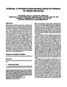
Experiments were designed to test both the effectiveness of the WID2 sensor node coupled with the proposed joint monitoring process. The sensor node was connected to three PZT enhanced washers that were mounted using 17 mm diameter steel bolts. A test setup of three instrumented washers and WID 2 is shown in Figure 16.
The tightness of the bolts was varied during the
experiment to test the sensor node’s ability to identify the state of each bolt. The WID2 was programmed to monitor the peak magnitude of the washer in the frequency range of 52-59 kHz and was configured to be triggered by the low frequency signal. For the host computer, which wirelessly receives the data from WID2, a MATLAB based graphical user interface was created to facilitate the data processing, as shown in Figure 17. The plot displays the inverse of magnitude. The threshold limit was set at 1000, which corresponds to 5 in-lb based on the calibration of WID2.
For the first test, all bolts were tightened to 240 in-lb of torque. As can be seen on the figure, all three bolts are well-below the threshold limit. For the second test, damage was introduced by loosing the middle bolt to hand-tightened. After triggering the sensor node, the damaged bolt 21
LA-UR-08-03404, Journal of Aerospace Engineering, Part G of the Proceedings of the Institution of Mechanical Engineers, accepted for publication
was clearly identified with the increase in the (inverse of) magnitude as shown in the plot. Finally, in the third test, the damaged bolt was retightened, and the values were returned to the undamaged condition, which is depicted in the figure. As can be seen, the proposed method shows the repeatability of measurement without the need of recalibration after retighten the bolt.
Figure 16: WID 2.0 with PZT enhanced washers.
First test Third test Second test
Figure 17: Experimental results with WID 2.0 for joint monitoring.
22
LA-UR-08-03404, Journal of Aerospace Engineering, Part G of the Proceedings of the Institution of Mechanical Engineers, accepted for publication
The measure and transmit operations take a combined time of 6 seconds to complete. By using the wireless data transmit and wireless triggering option, the joint preload assessment using the proposed concept and WID 2 can be made very quickly in an entirely wireless manner. With the wireless triggering option, the sensor node can be mounted on several locations in order to monitor bolted joints scattered throughout a structure. A mobile host is then search for the sensor nodes on the structure and gathers critical data needed to perform the joint health evaluation. This integrated technology can be adapted and applied to joint damage detection in a variety of engineering structures such as pipelines, naval vessels, hazardous waste disposal containers, and commercial aircraft. As with the success in the approach, future investigations should consider new configurations of material and geometry for future PZT enhanced washers. The strain characteristics of the washer/nut should be better understood/tailored so they can be matched to the desired threshold value of preload. This understanding will allow custom impedance signatures to be created that will better facilitate signal classification, and will permit the design of the proposed device that will enhanced performance at various preload levels. It is also possible to integrate traditional impedance methods with the proposed devices. The traditional impedance sensor can identify the damaged region, and then the proposed device can be used to precisely locate the damaged bolt. Finally, as with any other SHM systems, the long-term reliability and robustness of the proposed joint monitoring system should be verified for real-world field applications.
CONCLUSION In this paper, the concept of PZT enhanced washers was developed to continuously monitor the condition of a bolted joint in order to overcome limitations imposed by traditional monitoring
23
LA-UR-08-03404, Journal of Aerospace Engineering, Part G of the Proceedings of the Institution of Mechanical Engineers, accepted for publication
approaches. The mechanical impedance matching between the PZT enhanced devices and the joint connections was used as a key feature to monitor changes in preload. Our experimental results clearly indicate that the proposed devices can pinpoint the out-of-torque bolt with a minimum interaction with other structural and environmental variability.
This study also
propose the use of the wireless impedance devices with PZT enhanced washers, to replace traditional impedance analyzers, in order to make the proposed method a cost effective and portable for real-world structural health monitoring applications. The performance of this device has been verified with experimental tests.
ACKNOWLEDGMENTS This research was funded by part of the LANL/UCSD Education Collaboration Tasks. Thanks are extended to Mr. Eric Flynn for creating a graphical user interface for WID2.
REFERENCES
1. Nai N., Hess D., Experimental Study of Loosening of Threaded Fasteners due to Dynamic Shear Loads, Journal of Sound and Vibration, 2003a, 253(3), 585-602. 2. Nai N., Hess D., Influence of fastener placement on vibration-induced loosening, Journal of Sound and Vibration, 2003b, 268, 617-626. 3 . Junker G., New Criteria for Self-loosening of Fasteners Under Vibration,” S.A.E. Transactions, 1969, 78, 314-335 4. Nichols J., Nichols C., Todd M., Seaver M., Trickey S., Use of data driven phase space models in assessing the strength of a bolted connection in a composite beam, Smart Materials and Structures, 2004, 13, 241-250.
24
LA-UR-08-03404, Journal of Aerospace Engineering, Part G of the Proceedings of the Institution of Mechanical Engineers, accepted for publication
5. Nichols J., Todd M., Wait J., Using state space predictive modeling with chaotic interrogation in detecting joint preload loss in a frame structure, Smart Materials and Structures, 2003, 12, 580-601. 6. Ritdumrongkul S., Abe M., Fujino Y., Miyashita T., Quantitative health monitoring of bolted joints using a piezoceramic actuator-sensor, Smart Materials and Structures, 2004, 13, 20-29. 7. Park G., Sohn H., Farrar C., Inman D.J. Overview of Piezoelectric Impedance-Based Health Monitoring and Path Forward, Shock and Vibration Digest, 2003, 35, 451-463. 8. Park, G., Cudney, H., Inman, D.J., Feasibility of Using Impedance-based Damage Assessment for Pipeline Systems,” Earthquake Engineering & Structural Dynamics Journal, 2001, 30, 1463-1474. 9. Yang, J., Change, F.K., Derriso, M.M., Design of a Hierachical Health Monitoring System for Detection of Multilevel Damage in bolted Thermal Protection Panels: A preliminary Study, International Journal of Structural Health Monitoring, 2003, 2, 115-122. 10. Tanner, N.A., Wait, J.R., Farrar, C.R., Sohn, H., Structural Health Monitoring using Modular Wireless Sensors, Journal of Intelligent Material Systems and Structures, 2003, 14, 43-56. 11. http://www.xbow.com/ 12. Allen, D., Sohn, H., Worden, K., and Farrar, C., Utilizing the Sequential Probability Ratio Test for Building Joint Monitoring.” Proc of SPIE Smart Structures Conference, 2002, San Diego, March. 13. Todd, M. D., Nichols, J. M., Nichols, C. J., Virgin, L. N., An Assessment of Modal Property Effectiveness in Detecting Bolted Joint Degradation: Theory and Experiment, Journal of Sound and Vibration, 2004, 275(3-5), 1113-1126.
25
LA-UR-08-03404, Journal of Aerospace Engineering, Part G of the Proceedings of the Institution of Mechanical Engineers, accepted for publication
14. Gaul, L., Nitche, R., Friction Control for Vibration Suppression, Mechanical Systems and Signal Processing, 2000, 14(2),139-150 15. Park G., Muntges D., Inman D., Self-Repairing Joints Employing Shape-Memory Alloy Actuators, JOM-Journal of Minerals, Metals, and Materials Society, 2003, 55, 33-37. 16. Sun, F.P., Chaudhry, Z., Liang, C., Rogers, C.A., Truss structure integrity identification using pzt sensor-actuator, Journal of Intelligent Material Systems and Structures, 1995, 6, 134–139, 1995. 17. Giurgiutiu, V., Zagrai, A., Bao, J.J. Damage Identification in Aging Aircraft Structures with Piezoelectric Wafer Active Sensors, Journal of Intelligent Material Systems and Structures, 2004, 15, 673-688. 18. Bhalla, S., Soh. C.K., Structural impedance based damage diagnosis by piezo-transducers, Earthquake Engineering and Structural Dynamics, 2003, 32, 1897-1916. 19. Park, S., Lee, J.J., Yun, C.B., Inman, D.J., A built-in active sensing system-based structural health monitoring technique using statistical pattern recognition, Journal of Mechanical Science and Technology, 2007, 21, 896-902. 20. Peairs, D., Park, G., Inman, D.J., Improving Accessibility of the Impedance-based Structural Health Monitoring Method, Journal of Intelligent Material Systems and Structures, 2004, 15, 129-140. 21 . Grisso, B.L., Inman, D.J. Autonomous Hardware Development for Impedance-based Structural Health Monitoring, Journal of Smart Structures and Systems, 2008, 4, 305-318. 22. Mascarenas, D.L., Todd, M.D., Park, G., Farrar, C.R. Development of an Impedance-based Wireless Sensor Node for Structural Health Monitoring, Smart Materials and Structures, 2007, 16, 2137-2145.
26
LA-UR-08-03404, Journal of Aerospace Engineering, Part G of the Proceedings of the Institution of Mechanical Engineers, accepted for publication
23. Overly, T.G., Park, G., Farrar, C.R., Allemang, R.J. Compact Hardware Development for Structural Health Monitoring and Sensor Diagnostics using Admittance Measurements, Proceedings of IMAC-XXV, A Conference & Exposition on Structural Dynamics, 2007, Orlando, FL. 24. Overly, T.G., Park, G., Farinholt, K.M., Farrar, C.R. “Development of New Generation of Impedance-based Wireless Sensing Device,” Smart Materials and Structures, 2008, 17, 065011.
27