In this paper we consider ZigBee and, in particular, the lower layers of its ... edgements and retransmissions to higher levels of the communication stack. The.
A low power routing algorithm for localization in IEEE 802.15.4 networks Luca Bergesio, Paula Tarrío, Ana M. Bernardos, José R. Casar Data Processing and Simulation Group, ETSI. Telecomunicación Universidad Politécnica de Madrid, Madrid, Spain {luca.bergesio, paula, abernardos, jramon}@grpss.ssr.upm.es
Abstract. Many context-aware applications rely on the knowledge of the position of the user and the surrounding objects to provide advanced, personalized and real-time services. In wide-area deployments, a routing protocol is needed to collect the location information from distant nodes. In this paper, we propose a new source-initiated (on demand) routing protocol for location-aware applications in IEEE 802.15.4 wireless sensor networks. This protocol uses a low power MAC layer to maximize the lifetime of the network while maintaining the communication delay to a low value. Its performance is assessed through experimental tests that show a good trade-off between power consumption and time delay in the localization of a mobile device. Keywords: routing, wireless sensor networks, low power listening, localization.
1 Introduction User's location is a valuable source of information in many applications, including augmented reality, location-based services or interactive user experience [1-2]. A common approach to determine the position of a user in an outdoor environment is to use a GPS device. However, GPS is not so effective in indoor environments, and other technologies, such as Wi-Fi, Bluetooth or ZigBee can be used instead. In this paper we consider ZigBee and, in particular, the lower layers of its communication stack (IEEE 802.15.4 [3]). This technology was designed for Low-Rate Wireless Personal Area Networks (LR-WPANs) and has become very popular for wireless sensor networks (WSN). It is characterized by low data rate, low radiofrequency (RF) power, long battery life and low cost of the devices. A typical location-aware IEEE 802.15.4 network is composed of several static nodes with known positions and one or several mobile nodes whose positions need
2
to be calculated at different time instants. In order to estimate a mobile node’s position, the static nodes measure the RSS of the messages sent by the mobile node (or vice versa). From a set of RSS measurements the position of the mobile node can be calculated using a localization method based on fingerprinting [4] or channel modeling [5]. Due to the limited transmission range of IEEE 802.15.4 devices, covering a large deployment area requires the use of a multi-hop routing algorithm to collect the RSS data in a central server or to disseminate location information over the network. In this paper we consider the problem of providing a routing mechanism to perform centralized RSS-based localization in an IEEE 802.15.4 network covering a large deployment area. Since the nodes may be battery powered, our main objective is to minimize power consumption and maximize the lifetime of the network. We also consider the time delay in getting the location information as another important aspect. The structure of the rest of the paper is as follows. Section 2 provides some background on energy saving techniques for wireless networks. Section 3 describes a method to perform the RSS data collection using a low power multi-hop routing algorithm, which is evaluated in Section 4. Section 5 presents some conclusions and future research work.
2 Background One of the most common and effective techniques to reduce power consumption in wireless networks consists in switching off the radio transceiver as much as possible, because it is the most energy consuming hardware component of a node [6]. Since the RF transceiver is usually controlled by the MAC layer, numerous MAC protocols have been proposed in the literature to reduce energy consumption. Some MAC protocols use time slots to synchronize the communications between the nodes (e.g. S-MAC, T-MAC, etc.) [7]. These algorithms are quite complex and require precise timers, a resource that is not usually available in WSN devices. Another class of MAC protocols is based on CSMA-CA: they do not require synchronization, but they listen to the channel before transmitting, and only transmit if it is clear. Since this approach does not require synchronization, it is quite easy to implement on simple devices. TinyOS [8], an open source operating system developed by the University of California at Berkeley and widely used in WSN research, supports some notsynchronized protocols, namely, Berkeley MAC (BMAC) [9] and low power listening (LPL) [10]. BMAC is a beta version and will be probably replaced by XMAC [11] on the next version of TinyOS. LPL is stable and available on TinyOS 1.x and 2.x. In the contributing code to TinyOS 2.x repository [12], there are some examples of routing protocols based on low power listening MAC. One of those is the
3
Ad hoc On-Demand Distance Vector (AODV) routing protocol [13], one of the most popular algorithms for WSNs. This algorithm finds the shortest routes between the nodes and the base station, but leaves the management of acknowledgements and retransmissions to higher levels of the communication stack. The routing algorithm proposed in this paper is also based on a low-power MAC, but tries to find the quickest route from the base station to the other nodes, in order to introduce shorter delays in the communications. Furthermore, it handles acknowledgments and retransmissions in order to guarantee the reception of the RSS measurements collected by the nodes.
3 Proposed algorithm In this section we describe a routing mechanism specifically designed to collect RSS measurements in an IEEE 802.15.4 network covering a large deployment area. The proposed algorithm aims at collecting the measurements that are required to perform the localization of a node using multi-hop communications (to cover the whole deployment area) and low-power mechanisms (to extend the lifetime of the network as much as possible). Our routing algorithm is based on the LPL MAC layer of TinyOS and opportunistic routing [14]. The opportunistic routing is based on the availability of broadcast transmissions in wireless networks: a node can communicate simultaneously with all the nodes within its communication range. Using the idea of opportunistic routing and the LPL MAC protocol, our algorithm traces the paths between each node and the root on an on-demand basis. Then, the nodes use these paths to report the RSS measurements to the base station. We next describe the MAC and routing layers of the proposed algorithm. 3.1
MAC layer
Our routing algorithm works on top of the LPL MAC algorithm offered by TinyOS, which does not need synchronization and is quite easy to configure and control. The LPL algorithm uses a duty cycle mechanism to put the node into sleep mode periodically and save energy. The only parameter that needs to be set is the duration of a cycle, which determines the duty cycle (active listening time cannot be configured and it is set by default to the minimum value permitted by the RF transceiver). With LPL each device listens to the channel periodically and go back to sleep. If a node wants to transmit a message to another node, it must transmit during a full cycle to ensure that the receiver is listening to the channel while the packet is being sent.
4
In TinyOS this long transmission is made by sending many small packets covering the whole cycle. Each of these packets may contain either useful data or simply preamble information. In our implementation we have chosen to send these packets with useful information (data packets). 3.2
Routing protocol
The routing protocol consists of two phases. The first one is the discovery phase, in which the routing algorithm finds the routes between the nodes of the network (in particular, the routes to reach the base station from any other node). These routes are then used in the second phase, the reply phase, when a node needs to send data packets to another node (in particular, when a node sends the collected RSS information back to the base station). 3.2.1
Discovery phase
We assume that, at the beginning of the first phase, the nodes do not have any information about which are their neighbors or about the position of the mobile node. Under these circumstances, the easiest way to reach the mobile node is to broadcast a start transmission message from the base station. Then, each node retransmits the message once, generating a flooding. With this technique we ensure that each node receives the message, including the mobile node. This start transmission message carries six fields: source address, destination address, sequence number, intermediate source, hop count and action, as shown in Figure 1. The first is the address of the base station, typically zero. The second is the address of the mobile node we want to localize. It is possible to handle various mobile devices by changing this address. The sequence number is used to identify the packet, and thus, to avoid duplicate deliveries during the flooding mechanism. The intermediate source address is the most important field for the routing algorithm. It stores the address of the node that has most recently retransmitted the message. This address will represent the next hop towards the base station during the reply phase and it is saved in the node’s routing table. The hop count stores the number of hops; it is used only for debugging and statistic purposes. The last field is the command we want to send to the mobile node and can be set either to start or to stop (we will consider other possibilities in the future).
5
Figure 1: Structure of a start transmission message When the mobile node receives the start command it begins to transmit packets periodically (it stops transmitting when it receives the stop command). When this occurs, some of the static nodes (those that are close to the mobile node) receive these packets and measure their RSS. The next step consists in sending these RSS values to the base station. 3.2.2
Reply phase
At this point each static node knows the address of a neighbor towards the base station (the intermediate node memorized in the discovery phase). The static nodes that have measured the RSS from the packets sent by the mobile node will retransmit this information to their next-hop neighbors, and the procedure will be repeated until all the RSS measurements reach the base station. Clearly, if a link fails at a given moment, the packet will not be received by the base station, and this could affect the localization. To avoid this situation, a mechanism is needed to detect this kind of failures. In order to detect link failures we use the concept of opportunistic routing. When a node transmits a packet, it starts a timer and listens to the channel. If it detects a packet sent by its intermediate neighbor before the timer has expired, it considers that the transmission was successful. A data packet has the following fields: source address, destination address, next hop, intermediate source address, hop count, uniqueID and RSS data, as shown in Figure 2. The first is the address of the node which has measured the RSS. The destination address is the address of the base station (typically zero). The next hop is the address of the intermediate neighbor stored by each node during the discovery phase. The intermediate node is the address of the node which sent the packet in the previous hop. The uniqueID field is used to avoid possible collisions. It contains a random value generated by the node that begins the communication toward the base and it does not change during the trip. Finally, the last field of the data packet contains the original RSS measurements.
6
Figure 2: Structure of a data packet The algorithm works in this way. Let A, B, C and D be four static nodes (see Figure 3), with C being the base station. Node A measures the RSS of a packet sent by the mobile node, puts the data into a message, generates a random uniqueID, starts its timer and sends the packet to its intermediate neighbor, for example B. So the next hop address contained into the packet is B. This packet is received by both B and D. D checks the next hop field, and discards the packet, since it was directed to B. On the other hand, B checks the next hop field and accepts the message. Then it writes its address into the intermediate address field and the address of its next hop neighbor (C) into the next hop field, while the other fields are not changed. Then, it starts its timer and sends the packet to node C. C receives the packet, but due to the broadcast nature of the channel, A receives it too. If the timer of A has not yet expired, it checks if the intermediate address field is equal to its next hop neighbor (in this case B=B), in order to know whether the packet was generated by itself. Then it checks the uniqueID: if it is the one it generated before the transmission is considered successful. This uniqueID prevents possible collisions that could happen otherwise if two or more routes pass through the same node (imagine, for instance, a packet generated by a node E, following the route E-B-C, that is received by A).
Figure 3: Example of a small network With this technique we consider a data packet as an acknowledgement. If a packet is not received before the timer expiration, we consider that the link has
7
failed. Note that the base station has to send a packet too when it receives a message to avoid that the node sent the packet falling into the link failure case. 3.2.3
Link failure
If a timer expires before the node receives the acknowledgement, we consider that the transmission has failed and that the link is unavailable. The node passes then into a recovery mode. In this case the node re-sends the packet, but introducing the broadcast address into the next-hop field. In this manner each node that receives the message will try to forward it to the base station using its own next-hop neighbor. In this recovery mode the behavior can be configured to achieve a higher delivery rate. The node can restart its timer and repeat the retransmission several times. However one packet can be enough, especially if the network is dense and each node has several neighbors.
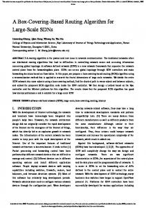
4 Experimental evaluation In this section we present the results of some experiments that were carried out to test the performance of the proposed algorithm in terms of energy consumption and communication delay. We implemented this algorithm in TinyOS 2.x for IRIS motes [15] and we deployed in our laboratory a small network, composed of ten static nodes, one mobile node and one base node connected to a computer. The first experiment was aimed at evaluating the power consumption of the proposed algorithm and, in particular, at evaluating the energy reduction due to the use of the low-power MAC layer. To this end, we used the BatteryC module of TinyOS to measure the voltage level of the batteries of the nodes. We carried out one test running the proposed algorithm (with the LPL MAC layer) and then repeated it without the LPL MAC layer. Figure 4 shows the evolution of the voltage level (average voltage of the ten static nodes) in the two cases. The red line is referred to the case with LPL, while the blue one is referred to the test without the LPL MAC layer. From these data, and taking into account that the nodes stop working when the voltage goes below 2.2 V, we can estimate a battery life of 3 days without using the low power listening and 53 days with the low power listening MAC (with a new discovery phase each 10 seconds).
8
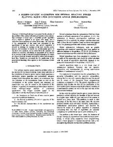
Figure 4: Battery life w/ LPL and w/o LPL The use of the LPL MAC layer reduces the energy consumption and increases the battery lifetime, but on the other hand, it introduces some delay in the multihop communications. According to the literature [11] the communication delay is equal to the product of the cycle duration and the length of the path. For example, as shown in Figure 5, the delay to complete the path A-C-D should be twice a full cycle: At instant 1, A wants to communicate with C, so it begins sending the preamble, followed b the data. C wakes up at instant 3, and receives a small part of preamble (represented in black in the figure) and then the data (shown in green). At this point C wants to send this packet to D, so it begins sending the preamble at instant 4. D wakes up at 5, receives part of the preamble and then the packet. At instant 6 the communication has terminated. The delay is 2 full cycles (a full cycle is the time between the beginning of a white small square and the beginning of the next one).
Figure 5: Classic LPL behavior In our implementation, this does not happen because the preambles in TinyOS are composed of many small messages. In this way, a mote can receive packets between a small message and the following. Since we use data packets in the preambles, the delivery is faster than in the classic case and delay is a random varia-
9
ble. In the worst case, the delay will be equal to the delay of the classic case, but in general, it will be lower and its value will depend on the load of the network. Moreover, the TinyOS scheme enables mixed or interleaved communications, which are not possible with the classical scheme. For example, imagine that in Figure 5, both A and B want to send a packet to D (through C): B wants to communicate with C at instant 2. Since the channel is busy it must wait until the channel is free, which happens only at instant 6. Then the communication B-C-D ends at the end of the green square of D. It does not matter which node (B or C) gets the channel at instant 4, the delay for the entire communication A-C-D and B-C-D is four full cycles. However, in our implementation the delays are much smaller (see Figure 6), because at instant 2 (the instant is the same in Figure 5 and Figure 6), B can start sending data to C. At instant 4, C has received both packets from A and B, and at 5 both communications end. In this example, both transmissions A-C-D and B-C-D take only one full cycle to complete, but they could take more if there were others nodes or if the packets were bigger than 29 bytes (the maximum payload for a TinyOS packet).
Figure 6: TinyOS LPL behavior Due to the behavior described above, the real delay in our implementation is smaller than in the classical case. We carried out a set of experiments to measure the delay in the discovery of a mobile node for different networks (2, 3 and 4-hop networks). A 2-hop network is composed by the base station, one static node and the mobile node; a 3-hop network has two static nodes and a 4-hop network has three static nodes. The delay was measured as the round trip time from the base station, to the mobile node and back to the base station. A total of 20 experiments were carried out for each type of network. Table 1 shows the average delay values obtained for the different types of networks. Table 1: Average delay in milliseconds for 2, 3 and 4-hop networks. 2-hop 1065 ms
3-hop 1797 ms
4-hop 2563 ms
10
We can observe that the round trip delay increases 700-750 ms for each new hop. Note that in this test we set a full cycle time of 1000 ms, so in the classical LPL behavior the delays would be 4000 ms, 6000 ms and 8000 ms for 2, 3 and 4hop network respectively.
5 Conclusions In this paper we have presented a low power routing algorithm for localizationaware applications. The algorithm is based on the LPL MAC layer provided by TinyOS and the concept of opportunistic routing, and was conceived to provide a low-power mechanism to find the routes towards the base station for the RSS measurements collected by the nodes of the network. We deployed a real network of ten nodes to test the performance of our algorithm. As shown in the experiments we obtained a battery life almost 20 times greater with the LPL MAC than without that MAC layer. Furthermore, the delay in the discovery of a node is lower than in classical duty cycle schemes due to the behavior of TinyOS LPL. Further research should be focused on improving the routing performance, especially during the discovery phase avoiding the flooding. This could be done using the coordinates of the static nodes, since these values can be established during the network deployment. Another aspect that can be further analyzed is the delay introduced by the duty cycling scheme. We are planning to evaluate the delay as a function of the path length, the hop count, the duty cycle and the network load in order to find the relations between these factors which could be useful when designing location-aware applications. Acknowledgements. This work has been supported by the Government of Madrid under grant S2009/TIC-1485 (CONTEXTS) and by the Spanish Ministry of Science and Innovation under grant TIN2008-06742-C02-01. References 1.
2. 3.
Liu, H., Darabi, H., Banerjee, P. and Liu, J., ―Survey of wireless indoor positioningtechniques and systems‖, IEEE Transactions on Systems, Man and Cybernetics, 2007. Part C: Applications and Reviews 37(6), 1067–1080. Gezici, S., ―A survey on wireless position estimation‖, Wireless Personal Communications 2008, 44(3): 263–282. IEEE 802.15.4 Standard, IEEE Standard for Information technology - Telecommunications and information exchange between systems - Local and metropolitan area networks - Specific requirements. Part 15.4: Wireless Medium Access Control (MAC) and Physical Layer (PHY) Specifications for Low-Rate Wireless Personal Area Networks (WPANs), 2006.
11
4. 5. 6. 7. 8. 9.
10.
11.
12. 13. 14.
15.
Lorincz, K. and Welsh, M., ―MoteTrack: a robust, decentralized approach to RF-based location tracking‖, Personal and Ubiquitous Computing, 2007, 11(6): 489–503. Li, X., ―RSS-based location estimation with unknown pathloss model‖, IEEE Transactions on Wireless Communications, 2006, 5(12): 3626–3633. Anastasi, G., Conti, M., Di Francesco, M. and Passarella, A., ―Energy conservation in wireless sensor networks: A survey‖, Ad Hoc Networks, 2009, 7(3), 537–568. Bachir, A., Dohler, M., Watteyne, T., Leung, K., ―MAC essentials for wireless sensor networks‖, IEEE Communications Surveys & Tutorials, 2010. TinyOS Community Forum: http://www.tinyos.net. Polastre, J., Hill, J., Culler, D., ―Versatile low power media access for wireless sensor networks‖, In SenSys 04: Proceedings of the 2nd international conference on Embedded networked sensor system: 95—107, New York, 2004. Jurdak, R., Baldi, P., Videira Lopes, C., ―Energy-aware adaptive low power listening for sensor networks‖, In proc. 2nd international workshop for networked sensing systems, San Diego, 2005. Buettner, M., Yee, G., Anderson, E., Han, R., ―X-MAC: A Short Preamble MAC Protocol For Duty-Cycled Wireless Networks‖, Technical Report CU-CS-1008-06, University of Colorado at Boulder, 2006. TinyOS 2.x Contributing Code: http://tinyos.cvs.sourceforge.net/viewvc/tinyos/tinyos2.x-contrib/ AODV Routing RFC: http://www.ietf.org/rfc/rfc3561.txt Liu, H., Zhang, B., Mouftah, H., Shen, X., Ma, J., ―Opportunistic routing for wireless ad hoc and sensor networks: Present and future directions‖, IEEE Communications Magazine, 2009, 47(12): 103—109. IRIS Datasheet: http://www.memsic.com/products/wireless-sensornetworks/wirelessmodules.html.