support multimedia applications over the wireless interface, and the implementation of this MAC on a Texas Instruments. (TI) Digital Signal Processor (DSP). 1.
A MAC Framework for Multimedia Application Support in WATM Dale How, Patrick Atkins, Neco Ventura Department of Electrical Engineering, University of Cape Town, Rondebosch, Capetown, South Africa {dale, patrick, neco}@crg.ee.uct.ac.za Keywords: MAC, Multimedia, QoS, WATM Abstract – Wireless ATM (WATM) is being researched as a way of providing wireless users with seamless access to a fixed ATM network. The Medium Access Control (MAC) layer within a WATM network is possibly the most critical layer within the system, as it is responsible for allocating the limited wireless bandwidth to users. Performing this allocation efficiently and minimising the amount of contention for resources as well as the number of collisions between transmitters is vital to a successful system. It is important that the scheduling is tailored to support multimedia applications with their stringent traffic requirements and is fair in allocation of channel bandwidth. In this paper a system is therefore proposed in which any MAC could be implemented and tested in a real world environment. This paper then discusses a MAC layer that will fully support multimedia applications over the wireless interface, and the implementation of this MAC on a Texas Instruments (TI) Digital Signal Processor (DSP).
1. INTRODUCTION Recent trends indicate that users value mobility. The universal use of cell phones in everyday life is testament to this fact. Another trend is that the prevalence of multimedia has become far more common than in the past, with people making use of video, data and voice to communicate, advertise or entertain. The goal of this project is to work towards combining the two, in order to make high bit-rate multimedia streams available to a wireless end-user. An architecture has been designed to allow mobile users to connect to a wired ATM network. ATM was chosen because of its inherent support for different classes of service and the guarantees that it offers once a connection has been established. These classes of service and their associated guarantees are essential, as multimedia has very specific requirements in terms of Quality of Service (QoS). The requirements include keeping delay and delay variation at a minimum and preventing excessive cell loss. Essential to the provision of a transparent, wireless access is a good MAC layer. This layer is responsible for the allocation of the limited wireless bandwidth to the mobile terminals for the transmission of their data. The MAC layer must minimise delay and variations in delay while scheduling traffic. There is no MAC that is perfect for all applications, and it is because of this that various classes of MAC protocols have been created to cater for different The authors would like to thank Telkom SA, Siemens, National Research Foundation (NRF) and The Department of Trade and Industry (DTI) for supporting this research project.
needs. There are four main groups (although there are hybrid schemes) of MAC layers, classified according to the mechanisms used to schedule traffic. These four types are listed below. Fixed Assignment – This method allocates a fixed amount of bandwidth to each mobile. This is rigid and wasteful, as it does not make use of statistical multiplexing. It can, however, be effective in systems where the traffic arrival rate is fairly constant. Random Access – With this method each mobile attempts to transmit at any random time. If a collision occurs with another transmission the mobile simply attempts to transmit again at a later time. This method can provide no form of guarantees and will never achieve a very high utilisation of the channel bandwidth. An example of this method would be the ALOHA MAC [1]. Polling – A base-station using this scheme polls each mobile for it’s bandwidth requirements and then allocates the available bandwidth based on the replies from the mobiles. This method can cause delays in transmission, as the mobile has to wait to be polled. Demand Assignment – A mobile using this method asks the base-station for permission to send data. The basestation allocates the uplink slots according to the mobile’s requests. This method is by far the most flexible and has a higher utilisation of the channel bandwidth when compared to fixed or random access schemes, especially when there are many users. It is for these reasons that this type of MAC is suited to scheduling multimedia traffic over the wireless medium. Most research into MAC layers is performed using simulation only; the MAC is seldom implemented in a physical system. Also, most proprietary wireless systems that have been researched (such as Intersil’s PRISM chipset for wireless LAN applications [2]) contain MAC layers that cannot be modified for experimental purposes due to high levels of integration onto single chip technology. It is for these reasons that a system that will allow the implementation and testing of any MAC layer in a working WATM environment is currently under investigation. The focus of this project is on implementing a MAC framework. Once a framework capable of implementing any MAC algorithm is in place the Wireless Dynamic Weighted Earliest Deadline First (WDWEDF) MAC will be implemented using the system. This MAC is of the demand assignment type, making it well suited to carry multimedia. It was also chosen because it has support for the ATM classes of service and has various mechanisms that allow it to minimise the amount of collisions between transmissions
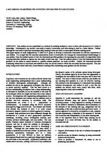
as well as the bandwidth wastage due to physical layer overhead. The rest of this paper is arranged as follows. The following section will deal with the design of the system. Further discussion of the MAC protocol and the mechanisms that it uses can be found in section 3. Section 4 will then deal with the choice of DSP, as well as the software that will be used to program and debug the DSP. Section 4 will also discuss the planned software architecture. Section 5 will outline the sections that have already been implemented, and provide some more details about them. 2. OVERALL SYSTEM DESIGN A centralised system where a base-station allocates bandwidth to mobile terminals that fall within its area of coverage is being considered. This will allow the system to be used as an extension to the existing ATM network. The hardware architecture of the system will be modelled on the work done by the Technical University of Berlin [3] and is shown in fig. 1. Unfortunately the system built by the Technical University of Berlin was not designed to support WATM or its requirements for high bit rates. Also, because they are only interested in investigating the qualities of the wireless medium, their MAC simply transmits packets one after the other, in a FIFO fashion. Furthermore, they have experienced problems with the speed of the microprocessor, as it is not capable of continuously streaming packets. A delay must be inserted between packets to allow time for the relevant interrupts to be processed. The Intersil 802.11b hardware that the Technical University of Berlin used in their design is also no longer manufactured. Subsequent versions of Intersil’s 802.11 PRISM chipsets [2] incorporate the MAC layer and the base band processor onto the same chip, making them impossible to separate. It is for this reason that the physical link will therefore have to be emulated in our system. For future projects, the physical layer could be implemented using Orthogonal Frequency Division Multiplexing (OFDM). OFDM counters common wireless medium issues, such as multi-path inter-symbol interference, by simultaneously transmitting multiple subcarriers at orthogonal frequencies. This method can handle many common channel impairments and multi-path effects and makes efficient use of the available bandwidth. Highspeed systems such as 802.11a [4] and HIPERLAN 2 [5] use OFDM instead of CDMA, as it provides better support for high bit rates. This makes OFDM an attractive option for the physical layer of our project [6]. Base station
Emulated Physical Medium
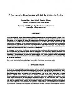
decided to implement the WDWEDF with two-phase scheduling MAC. This MAC layer is extensively discussed in [8] where the authors present it as an efficient way of supporting CBR, VBR, ABR or UBR ATM traffic. 3.1 The WDWEDF Algorithm The WDWEDF algorithm differentiates between the ways that it schedules traffic in the uplink and downlink streams. In the downlink stream, it uses Dynamic Weighted Earliest Deadline First (DWEDF) scheduling for the streams of traffic that it is broadcasting. It schedules this traffic using multiple stages. It first gives a priority to each link based on that link’s traffic class. Then, in the second stage, it prioritises each link within that traffic class according to the link state. DWEDF periodically calculates the link state of each of the links and makes scheduling decisions based on the state of the links. The link state is calculated based on the service class of the link, the required Mean Cell Rate (MCR) and Peak Cell Rate (PCR) values of each link and the current status of the MCR and PCR during the calculation period. In the uplink stream, the base-station does not have complete control over the links to make the necessary calculations for DWEDF scheduling. Therefore, the wireless terminal has to schedule its own connections and then provide information to the base-station about its requirements. The base-station then schedules uplink time to each mobile depending on the information sent by mobile terminals. This scheduling is referred to as “two-phase scheduling,” and it will be discussed further in the next section. 3.2 Frame Structure Fig. 2 below shows the frame structure of this MAC. The diagram has been adapted from a diagram in [8].
Wireless Terminal
Fig. 2. WDWEDF MAC Frame Structure MAC layer on a DSP
Fig. 1. System Architecture 3. THE MAC LAYER Many MAC layers have been studied and a great degree of similarity was found between MAC layers of a similar type (random, fixed and demand access) [1, 7]. It was
A packing algorithm is used to pack cells that have been scheduled for transmission into MAC Protocol Data Units (MPDU’s). Each MPDU is made up exclusively of cells from a single ATM Virtual Circuit (VC). In this way all cells going to the same destination are put into the same MPDU. This packing of cells minimises physical layer overhead by eliminating the need for physical layer overhead before the transmission of each cell. Minimising
physical layer overhead is crucial to wireless systems, where bandwidth is at a premium. Packing cells into MPDU’s also allows one to have a piggyback field per MPDU instead of per cell. The boundaries between transmission periods are moveable, allowing the MAC to adjust the time allocated to a certain type of traffic if needed. The frame header is responsible for carrying information regarding slot assignment and frame structure to the mobile terminals. The downlink period following the frame header is scheduled using the WDWEDF scheduling algorithm. Mobile terminals then transmit their CBR and VBR MPDU’s in the relevant uplink period, according to the slots assigned to them in the frame header. Supplemental scheduling is performed to allocate the remaining uplink slots. The control slot is a random access channel that is used for ABR, UBR or new connections to contend for bandwidth. Collisions occur in this channel, causing requests to be lost. Subsequent delays in cell transmission could violate the maximum cell delay of a VBR source if it were required to contend for bandwidth in the same way as the ABR, UBR or new sources. The two-phase scheduling algorithm effectively eliminates the need for VBR sources to contend for bandwidth in this way. It uses “piggybacking” to allow VBR sources to request additional bandwidth (VBR sources are only allocated their minimum number of slots in the first phase) from the base-station as it is required. The piggyback field of MPDU’s successfully received by the base station in the first phase specifies whether a certain VBR source requires additional cells to be transmitted. It is this “piggybacked” information that is used to make decisions in the supplemental scheduling period. This method also reduces the amount of traffic in the contention channel and therefore reduces the chance of a collision occurring, improving the throughput of requests in the contention channel.
will allow communication with the physical layer to take place at speeds of up to 100Mbps [9]. The DSP has 128Kb of internal memory along with 256kb of external SBSRAM and 8 Mb of external SDRAM. Additional SDRAM can be added, up to a total of 512 Mb [10]. This memory will be sufficient for buffering cells and for storing control variables. TI’s software, Code Composer Studio 2, will be used to program and communicate with the DSP. This software package includes its own real-time kernel, DSP/BIOS [11], as well as a number a graphical kernel configuration tools along with various methods of monitoring the processes running on the kernel. This real time kernel allows prioritisation of functions according to their importance in the system. It also provides various methods of inter-process communication, such as semaphores and mailboxes. The time taken for each process to complete execution can be monitored using the processor monitoring tools embedded in Code Composer. This in turn allows the time that a cell spends in the MAC layer to be monitored, which is vital when attempting to adhere to real-time deadlines and guarantees. Data regarding the performance of a process as well as any outputs from the process can be logged to a file on the host computer, using the host-DSP communications that Code Composer Studio provides. This information can then be viewed in either real-time (in the form of a windowed display within Code Composer Studio) or in the file on the host computer after the DSP has been stopped. Fig. 3 is an image showing the software architecture of the system and illustrating the interaction between the various modules. It shows more clearly the section that will be implemented (the MAC layer.)
4. IMPLEMENTATION ON A DSP In order to build a system capable of implementing any MAC layer there are a number of requirements that must be met. A high bandwidth connection between the upper layers and the MAC layer must be available for the rapid transmission of data to the MAC layer for scheduling. The MAC layer must be able to communicate at high speeds with the physical layer. The MAC layer must be able to process and schedule data at a very high rate. The MAC layer must have sufficient memory available to buffer cells and to store its control information. A simple method of programming and debugging the MAC layer must be present. Research into various available DSP’s has been conducted and their conformity to the above criteria evaluated. The Texas Instruments (TI) TMS320C6201 fixed point DSP was finally chosen as the processor most suited to the system’s needs. It runs at a 200MHz clock speed, (up to 1600 MIPS) allowing it to process data at high speed. The DSP slots into the PCI slot on a host PC, allowing high data rates between the host and the DSP. It also has extension ports (Multi-channel Buffered Serial Ports or McBSP’s) that
Fig. 3. Software Architecture Within this figure, thick arrows represent data paths while thin arrows represent control paths. The transmission module is responsible for the assembly of MAC frames from cells that are passed down from the Logical Link Control (LLC) layer and control messages from the controller module. The controller module makes the scheduling and frame structure decisions, based on information received
from the transmission and receiver modules, as well as from higher layers (such as requests for retransmission.) The receiver module is responsible for disassembly of the received MAC frames and transferring the data into the correct information streams. Data packets are sent to the LLC layer for error checking/correction while signalling packets are sent to the controller module to aid it in making scheduling decisions. A method using the Direct Memory Access (DMA) controller onboard the DSP to perform data transfers to and from the physical layer, as well as to and from the higher layers when they are added, is currently under investigation. The DMA can perform these transfers with no CPU involvement, freeing up the CPU for other tasks. The DMA controller can also be synchronised with other peripherals. In this way one can ensure that data is not sent or received before the peripherals that are involved in the transfer are ready for the data exchange. 5. IMPLEMENTATION PROGRESS At the time of writing various parts of the final system have already been implemented. By using the DSP simulator available with Code Composer Studio one can write and test code without a DSP being present. Different modules run as separate processes, using inter-process communication to prevent simultaneous access to shared or global variables. Software interrupts are used to call the various functions when they need to be run. Hardware interrupts are used to signal completion of a McBSP or DMA transfer.
5.3 PACKING ALGORITHM As specified in the WDWEDF MAC, an algorithm to pack cells into MPDU’s for transmission has been implemented. This algorithm also makes use of pointer copying instead of copying all of the memory holding a cell. Each connection has a fixed sized array to store complete MPDU’s. 5.4 TRANSMISSION OF MAC FRAMES A simple FIFO scheduler is currently being used to schedule transmission of MPDU’s. A scheduler based on WDWEDF is currently being built. When selected for transmission, MPDU’s are moved into a DMA transmission buffer by a process that first converts the data elements within the MPDU into an array of elements in a contiguous memory block. The DMA controller is then used to transmit an MPDU to the McBSP. At the moment the McBSP is being operated in Digital Loop Back (DLB). In DLB mode the transmit and receive pins are connected in software. This is necessary because there are not yet any DSP’s to transmit information between. The McBSP and the DMA controller are synchronised with each other through the use of hardware interrupts. When the McBSP is finished transmitting a block of information, it signals to the DMA controller that it is ready for the next block. The DMA controller will then transfer the next block of information. 6. CONCLUSIONS
5.1. TRAFFIC GENERATOR As the layers above the MAC layer are not yet present in our implementation, there needs to be a method of generating traffic to be scheduled. At the moment the simplest form of constant arrival rate traffic is being used. This will be expanded to model the arrival rates of the various traffic types (voice, data and video.) The kernel calls the traffic generator process periodically by using software interrupts. The traffic generator then generates cells for each connection based on the cell arrival parameters associated with that connection. These cells are buffered in the buffer allocated for incoming cells from the relevant ATM VC. As the higher layers are added in subsequent projects one could change this process into one that reads cells from an external source, possibly using a DMA transfer, and puts them on the relative queues instead of generating them locally. An external interrupt can be used to signal when cells are ready to be read from the external source.
Wireless ATM MAC layers must provide efficiency in bandwidth usage while still maintaining ATM guarantees set up by each connection. Unfortunately, because proprietary wireless systems do not allow for modifications to be made to their MAC protocols, most MAC research has been done in simulation only. A system that will allow developers to implement and test MAC layers in a flexible environment has therefore been proposed. WDWEDF was evaluated and chosen as a viable MAC to support multimedia over WATM. Implementation of WDWEDF mechanisms has been started. Due to the unavailability of a MAC-less physical layer the physical transmission layer will be emulated to some degree initially. Using the DMA controller and the McBSP’s in this emulation enables future communication with an actual physical layer. For future work, the physical layer may be implemented using OFDM as the modulation technique of choice, as it is capable of meeting the requirements for a WATM link.
5.2 BUFFERS In order to simplify the data types used in the system we have implemented a buffer type that can hold any type of element. Buffers using this type pre-allocate all memory that they will use and make use of holding elements for dequeue/enqueue functions. This is done in an attempt to implement zero copying. Zero copying involves copying pointers only, instead of the entire cell when a cell is moved. In this way the amount of CPU time used to move data is reduced.
7. REFERENCES [1] Ajay Chandra, V. Gummalla, John O. Limb, “Wireless Medium Access Control Protocols,” IEEE Communications Surveys, available: http://www.comsoc.org/pubs/surveys [2] Intersil, PRISM wireless LAN, available: http://www.intersil.com/design/prism/index.asp [3] Christian Hoene, “Prototyping Environment for Link/MAC Layer Protocols,” available: http://www-tkn.ee.tu-berlin.de/~hoene/ [4] IEEE working group for wireless LAN’s, 802.11a and 802.11b specifications, available: http://standards.ieee.org/catalog/olis/lanman.html [5] Broadband Radio Access Networks (BRAN), “HIPERLAN Type 2 Data Link Control (DLC) Layer - Part 1: Basic Data Transport Functions,” available: http://www.etsi.org [6] Vijaya Chandran Ramasami, “Orthogonal Frequency Division Multiplexing,” available: www.ittc.ukans.edu/~rvc/acads/ofdmreport.pdf
[7] Osama Kubbar and Hussein T. Mouftah, “Multiple Access Control Protocols for Wireless ATM: Problems Definition and Design Objectives,” IEEE Communications Magazine, November 1997 pg. 93-99. [8] Sungwon Lee, Young-Jae Song, Dong Ho Cho, Yong-Bae Dhong, Jung-Won Yang, “Wireless ATM MAC Layer Protocol using WDWEDF and Two-phase Scheduling Algorithm,” IEICE Transactions on Communications Vol. E81-B, No.12 December 1998 pg 2432 – 2443. [9] Texas Instruments, “The McBSP as a high speed communications port,” spra455a.pdf, available: http://www.ti.com [10] Texas Instruments, “TMS320C6000 Peripherals Reference Guide,” spru190D.pdf, available: http://www.ti.com [11] Texas Instruments, “TMS320 DSP/BIOS Users Guide,” spru423A.pdf, available: http://www.ti.com