A Mediation Layer for Connecting Data-Intensive Applications to Reconfigurable Data Nodes Mohamad Jomaa, Khaleel Mershad, Noor Abbani, Yaman Sharaf-Dabbagh, Bashar Romanous, Hassan Artail, Mazen A. R. Saghir*, Hazem Hajj, Haitham Akkary, Mariette Awad Department of Electrical and Computer Engineering, American University of Beirut, Beirut, Lebanon * Electrical and Computer Engineering Program, Texas A&M University at Qatar, Doha, Qatar E-mails: {mfj03, kwm03, nma51, yxs00, bfr03, ha27, hh63, ha95, ma162}@aub.edu.lb *
[email protected] Abstract—A novel and rapidly growing area of research concerns data-intensive applications and the technical challenges that accompany it. One of those challenges is developing approaches and mechanisms that render high performance in processing and storing data. We joined this research effort by proposing a reconfigurable active solid state drives (RASSD) system that deals with such applications, through employing basic hardware, namely FPGA’s connected to SSD’s, to service the above applications as processing nodes, and take advantage of the close proximity between storage and processing. In this paper, we propose an intelligent middleware system for interfacing workstation-based and mobile applications to the distributed RASSD system. In order to provide high performance in terms of time and functionality, the middleware manages the data processing on the RASSD nodes through special pieces of code that we call drivelets, along with FPGA configuration files (bitstreams). Another important responsibility of the proposed middleware architecture lies in the unguided management of applications’ flows, where it uses an intelligent script-parsing mechanism to turn one general request from the client into a sequence of operations needed to generate the required results. The middleware design allows for the integration of mobile applications into the overall architecture of the RASSD system, and allowing them to run data intensive applications that otherwise it is unfeasible for them to execute. We validate our design by comparing it to an existing middleware architecture, and present two use-cases with their results and discussion. Keywords—Middleware; mobile applications; FPGA, solid state drives; distributed computing; drivelet; bitstream.
I.
INTRODUCTION
Data generation is increasing at such an exponential rate that in the last two years, 90% of the data in the world have been generated, whether it be sensor data, text, images, videos, signals, etc. Such giant amounts pose challenges for both the storage and the processing of data. In [1], we proposed a distributed, high performance platform for dataintensive applications that relies on a combined active solid state drive (SSD) and reconfigurable FPGAs as its computing nodes which we have named RASSD nodes. The SSD storage component is directly connected to the computation hardware to avoid data transfer over a network connection. The FPGA, on the other hand, is the computing
component that can reconfigure hardware according to the requirements of data processing applications. In [1] however, we only presented the architecture, as several of the system’s components were not functional yet, including the reconfiguration capability and the dynamic loading of compiled code (kernels) that are supposed to run right on the FPGA node. More critically, the acceleration capability was not completed as well. In the design, it is assumed that data is generated and collected in dispersed locations through third party applications that are not part of the proposed system. However, these data are stored on RASSD nodes, which form an integrated platform that may contain hundreds or thousands of RASSD nodes physically located in distributed and far apart geographical sites. The RASSD system is therefore meant to support multiple data-intensive applications with distinct processing and storage needs. More specifically, the hardware serves API requests made by client applications (regular and mobile), through a middleware layer, in a dynamic environment where data and computational requirements change unpredictably. In this paper, we present the technical design and implementation of the middleware, which was missing in [1]. This middleware plays the role of a mediator between applications and processing nodes, and hence, it hides the complexities associated with data distribution and with configuring and accelerating the RASSD hardware to suit the needs of the applications. For this reason, both regular (workstation-based) and mobile applications can access the system identically through proxies that are installed on the client hardware, in a way similar to how Web Services are accessed. The middleware therefore has to interpret the application workflow and requests, map each operation to hardware configurations and process jobs on reconfigurable FPGA nodes. Dealing with application workflows rather than with simplistic uni-operational requests necessitates a level of middleware intelligence that manages the stream of tasks needed to complete a request and handles intermediate results, without direct guidance from the client. Therefore, the latter only needs to submit a high-level request without going through the hassle of initiating each operation separately. To the best of our knowledge, this is a unique capability that a middleware architecture which interacts with reconfigurable hardware supports.
978-1-4673-5775-3/13/$31.00 ©2013 IEEE
The rest of this paper is structured as follows: Section 2 presents a literature survey comparing our middleware to other proposed middleware systems. Section 3 provides some needed background information on the rest of the system that the middleware operates within, while Section 4 presents the proposed design, including a description of the typical sequence of events for servicing a request, and a qualitative validation of the design through a comparison with another middleware system. Sections 5 and 6 present two implemented applications and their performance results, respectively. Finally Section 7 concludes the paper. II.
LITERATURE REVIEW
Despite being a fairly well established research subject, the work on developing new middleware models and frameworks is still attracting attention. This should not come as a surprise since middleware systems cater to the needs and trends of emerging hardware and software technologies. The work in [2] outlines the features of next generation middleware, which aims at achieving high levels of flexibility by supporting runtime reconfiguration and adaptability. To attain this goal, [2] proposes to follow a component-based programming paradigm that includes reflection. This concept was extended in [3] to satisfy emerging trends in mobile devices and environments. In particular, there is a need to address the constraints imposed on computation and resource-limited mobile devices as well as unstable wireless connectivity. Other requirements relate to decoupling the sender and the receiver in space and time. In [4], a new middleware architecture was proposed for distributed real-time and embedded systems. The middleware attempts to provide fault tolerance through adaptive and resource-utilization-aware failover backup management. The architecture decentralizes failure detection by adding monitors that collect resource utilization readings and failure event notifications, and reports them to a replication manager to provide transparent failure recovery. On the other hand, the authors in [5] propose a middleware to support the communication between software and hardware at runtime. Their system depends on generated data profiles for each application. Those profiles include the application’s tasks and whether they run on software or they can be accelerated using a hardware co-processor. The middleware uses those profiles as guidelines to manage communication between different tasks whether running on software or hardware co-processors using FIFO interfaces. The main limitation of this middleware is that it does not account for the distribution of data. In contrast, and in this context, our proposed middleware provides the abstraction for tasks running on different nodes to communicate through generating and consuming intermediate results. In [6], the authors introduce the concept of combining reconfigurable FPGAs with wireless sensor network nodes. For the completeness of their framework, they propose a support middleware for the real-time configuration of the reconfigurable nodes. The middleware is basically a module that resides on the node to reconfigure it according to the application needs, and therefore it lacks the need of processing data in dispersed locations. This middleware is
not as capable as the one we propose, from the point of view that our distributed middleware is not application-specific, as it works with different kinds of applications. Context-awareness also caught the attention of middleware researchers. A new middleware described in [7] tries to provide support for heterogeneity, mobility, scalability, privacy, traceability and control, and ease of deployment and configuration. This particular architecture was built on top of a distributed framework that provides context management and preference management, a toolkit to facilitate integration of applications, and a tool that assists with generating components. However, the proposed system does not support tolerance for failures which are common in context-aware mobile environments. Finally, it is worth noting the work in [8], which develops queuing network models (QNMs) to model individual components in a middleware. The authors claim that such a scheme will help developers reach development decisions based on predicted performance of certain functionality provided by the middleware. Most of the above-described middleware systems represent frameworks and models that are yet to be implemented and tested, although they can be used to guide the development and meet the expectations of application developers. Our middleware architecture does in fact capture several of the discussed features. As will be demonstrated, it is highly modular and distributed to enable running support functions and services where they are most needed. It also provides an intelligent abstraction layer for applications, and most importantly, it is capable of dynamically reconfiguring and accelerating programmable logic devices to achieve high performance and application adaptability. III.
BACKGROUND
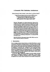
A. RASSD System Architecture The RASSD System, as detailed in [1], is composed of three layers: the application layer, the middleware layer, and the hardware layer. As its name indicates, the application layer represents the client applications that issue requests. The middleware layer abstracts the low-level details of the RASSD hardware and enables data-intensive applications to use these devices to achieve high levels of performance. The hardware layer consists of the geographically-distributed RASSD nodes that store and process data. Across the three layers, the overall system consists of the Application and Client Middleware (at the application layer), Middleware Servers (middleware layer) and the RASSD nodes (hardware layer). All components are connected together via WAN and LAN networks. By design, the Middleware Servers (MWS) are connected to the RASSD nodes via LAN network (i.e., geographically collocated). Each RASSD node comprises one FPGA board connected to one or more SSD devices over a PCIe interconnect. Applications running on PCs, laptop computers, and handheld devices (e.g., smartphones) can be clients that wish to run different data processing tasks and queries. Figure 1 provides an overall picture of the system.
Some parts of some drivelets represent very frequent and time-consuming functions, where the highest percentage of the drivelet time is spent. These functions can be turned into hardware accelerators that exploit the reconfigurable FPGA logic fabric to customize computations and achieve significant speedups over software implementations. D. Drivelet Integration into RASSD OS In our model, we develop drivelets using the C programming language, and use the Xilinx ML605 board as our RASSD node on which drivelets are installed. First, we make use of the Xilinx Software Development Kit (XSDK) to develop our RASSD OS platform. The interested reader can refer to [9] for details on the RASSD OS platform. For developing drivelets, we first write the drivelet code as a separate C program, and then import it into a new C project in our XSDK project explorer. A screenshot of the project explorer after adding the drivelet’s C code to it is shown in Figure 2 (included in a file named init.c). Figure 1. High Level Distributed RASSD System Architecture
B. RASSD Node OS A customized operating system (OS) is installed on each RASSD node for managing and monitoring its functionality. We proposed and implemented the RASSD OS in [9], with services such as initializing the RASSD node, configuring its various components, monitoring its activities, and processing middleware requests. The RASSD OS is implemented using the multithreading library of Xilkernel® to provide all OS services simultaneously. The main() thread permanently runs and controls all other threads, which include: • EMAC Handler: responsible for all the sending and receiving between the node and the MWS • Drivelet Loader: loads and launches the drivelets on the Microblaze processor • Dynamic Partial Reconfiguration Manager: configures the FPGA with the desired accelerator • Cache Controller: maintains storage of drivelets and accelerators bitstreams that have been loaded in the node • PCIe Controller: responsible for transferring data needed by the drivelet or the hardware accelerator from SSD’s to main memory • FTP Server: launched by main() to handle file transfers between the middleware and the RASSD node C. Drivelets and Bitstreams Data-intensive applications usually include several complex functionalities for pre-processing, classifying, processing, and/or post-processing the data. Each one can be mapped to a drivelet C code that implements the required operation. Drivelets are parameterized software modules designed to run on the RASSD MicroBlaze microprocessor to accomplish predefined data processing functions on identified data groups stored on the RASSDs themselves.
Figure 2. RASSD OS platform files in project explorer of XSDK
The next step is to modify the drivelet’s code so that it becomes compatible with RASSD OS. The main reason for which we need to modify the C code is that 1) the memory file system (LibXil FATFS) used by RASSD OS is designed to be a light weight MFS, 2) it does not support the FILE stream object in C, and 3) functions that take FILE stream objects as input or output parameter (fopen(), fgets(), etc.) cannot be used in RASSDOS. Instead, we declare buffers in memory that would hold the content of the file to be opened or stored, and then do the processing on these memory buffers. When saving data to file(s), we call specific functions from LibXil FATFS to take these buffers and save them into file(s) on the ACE compact flash on ML605. Finally, we transfer the data to the ML605 board and program it to run the RASSD OS Kernel and integrate the necessary drivelets. For this, we program the board with the RASSD hardware architecture, and then we use the GDB debugger to test the drivelet execution by the MicroBlaze soft-processor that is running on the ML605 board.
r ro e d
IV.
application), and sends the final results back to the client. We should note that this aggregation is a second level aggregation, as the MWSs themselves are responsible for aggregating the data from the various RASSD nodes they are connected to.
a o b ue Q l
ob Q a ue
E. Hardware Accelerator Integration The aforementioned prepared drivelets are sequential data-intensive code of assignments, computations, conditional statements, loops, functions, etc. Profiling the code generates the time for it to be executed as a whole in addition to a dissection of how much time is spent on each block. Application developers use profiling along with their expertise to choose parts of the code that consume most of the execution time which we call kernels. Now that we have the kernels that should be accelerated, they are written, offline, in a hardware descriptive language (HDL), VHDL, or Verilog, and hence transformed into hardware accelerators that make use of the hardware resources on the FPGA. Synthesizing this HDL code using the Xilinx Software Development Kit creates a bitstream file (an .elf file), which consists of a series of bits describing the FPGA logic resources’ connections and configurations (AND, OR, NAND gates, etc…), leading to the implementation of the specific kernel. Finally, this bitstream file is stored in the middleware’s kernel library for future use.
SD
MIDDLEWARE DESIGN
In order to account for the distributed aspect of the RASSD system and to manage the processing of jobs requested by different clients on the different nodes, we developed a distributed middleware system that plays the role of a mediator between the client application and the hardware nodes. The middleware’s responsibilities can be summed up through the following tasks: • Constantly wait for new requests from clients • Process the requests and prepare the jobs to be performed by the RASSD nodes • Delegate jobs to the appropriate processing nodes • Keep track of the different jobs being processed • Aggregate the results at the middleware level • Send the results back to the clients • Keep track of the different “alive” nodes in the system and the data residing on them. The middleware design we are proposing comprises three main entities: the Client Local Middleware (CLM), the Middleware Server (MWS), and the Data Site Schema (DSS). Figure 3 depicts the middleware architecture. A. Client Local Middleware (CLM) This is the middleware entity that is in direct contact with the application. As its name depicts, the CLM resides on the client side, i.e., one CLM is dedicated to every client host, constantly listening for new requests to service for this client. It is the CLM’s responsibility to contact the Data Site Schema to get the needed information regarding the distribution of the data on the processing nodes of the system, and contact the MWSs responsible for these nodes respectively. The CLM sends the necessary commands to the different MWSs, indicating the processing needed on the specified data, then waits for the results from these MWSs. Once the CLM receives all the results it is waiting for, it aggregates them (the aggregation function varies with the
Figure 3. General Architecture showing middleware components
B. Middleware Server (MWS) The core entity in our design is the Middleware Server (MWS). Unlike the CLM, the MWS is not dedicated to a certain client, but it is meant to serve several clients (through their CLMs) simultaneously. Typically, there are several MWSs strategically distributed on dedicated machines that are geographically close to their respective RASSD nodes. The MWS is the middleware entity that is in direct contact with the RASSD processing nodes. Each MWS is responsible for a group of hardware nodes, which is a highly geographically-dependent distribution. This responsibility includes assigning jobs to these processing nodes and monitoring the status of these jobs until they are completed and the results are sent back to the requesting CLMs. Hence, each MWS is constantly listening for commands originating from CLMs. Upon the receipt of a request, an MWS prepares the job to be sent and processed. For this, it contacts the DSS in order to get information about the RASSD nodes on which the concerned data resides. At this point, the MWS contacts these nodes and assigns the job to them while supplying them with the input data needed for the processing (received from the CLM, or from some or all of the nodes themselves (i.e., intermediate results). The results that are obtained by the MWS from the different nodes are aggregated at the MWS level and then sent to the requesting CLM. While this scenario depicts the general role of the Middleware Server, it remains a simplistic scenario. Section
V details the several possible more realistic scenarios, where more complex MWS operations are described. C. Data Site Schema This entity is considered part of the middleware and is composed of the databases that contain all the metadata and information needed to locate the data files needed. Also residing on one or more servers, the DSS contains the following information responsible for: • guiding the CLMs in locating the concerned MWSs • guiding the MWSs in locating the concerned RASSDs • tying the different processing functionalities to “drivelet” and “bitstream” files that can run on the RASSD nodes In sum, this entity of the middleware is involved in every preparatory step of the jobs to be sent to the RASSD nodes. However, it should be noted that caching at both the CLM and MWS levels can be employed to reduce the number of trips to the DSS sites. D. Interface As mentioned earlier, each node has an EMAC Handler that handles TCP/IP connections with the MWS. To standardize the communication between the MWSs and the RASSD nodes, we designed a communication protocol that defines the format of exchanged messages, including loading hardware accelerators, processing data, and returning results. There are other commands related to data manipulation to add, delete, or modify files on the node. Moreover, there is a set of reply messages from the node to the MWS to acknowledge the receipt of commands. E. Application Request Handling This section describes the sequence of events performed by the middleware when servicing a request. 1) Client-CLM Path Whenever the CLM receives a request from the client, its first task would be to check the command it received to detect the application it is servicing. This check helps the CLM in preparing the application virtual flowchart using its stored flow for the application. More specifically, every application type has a script stored on the middleware’s Data Site Schema, depicting the flow of operations that this application needs to perform in order to complete. This is a major functionality provided by our CLM to application developers. These do not need to trigger the operations they need to perform one at a time. Instead, all they need to do is provide the middleware with the flow of operations offline. The CLM reads the flow script after discerning the application that issued the request, and triggers all the operations and jobs needed from the concerned RASSD nodes (chosen based on the data distribution), then returns the end results aggregated to the client application. This flow detection mechanism and the exchanges and operations that take place for the processing of the request to be completed are transparent to the client. The manner with which our flow detection and management mechanisms works provides the application developers with flexibility, since the flow scripts can vary
from application to another. The first line in the script is read by the CLM in order to detect the type of information the script is providing, then the script is read and all the flow is prepared at the CLM level for processing. An example of the first three lines of a possible script is as follows: Operation_ID; Number_of_InputFiles; InputFile_1; ... ; Output_File Initialization; 1; state_simple.txt; Out_of_(1).txt Obtain_Visits; 2; Out_of_(1).txt; graph_simple.txt; Out_of_(2).txt
In the flow script example above, the first line indicates that the application developer is providing the input and output files’ names along with the operation to be performed, and the order of these pieces of information. The CLM fetches the following lines according to this order, and stores the information in the general flow of this request. The next step for the CLM is to contact the DSS again in order to decide on the MWSs to contact for each operation it fetched from the script. This choice is determined by the data distribution on the nodes, i.e., on which RASSD nodes the input files indicated in each operation reside. Using the “Operation” field, the CLM determines the drivelets and bitstreams that will be involved in performing this operation, with the guidance of the DSS as well. 2) CLM-MWS-RASSD Path Once the CLM is ready to contact the concerned MWSs, it sends them the commands for the requests they need to perform. After all the commands are sent, the CLM waits for the results from the different MWSs in order to send them back to the client. Once the MWS receives a command from a CLM, it proceeds with preparing the job that is to be executed on the RASSD nodes, which it locates with the help of the DSS. Each RASSD node is coupled with a queue at the MWS side, which stores all the jobs that this node has to execute. In case the node is idle, the job is directly passed to it. Otherwise, if it is executing an operation, a new job targeted at this node would be added to its queue then popped whenever it is ready for executing a different job. 3) RASSD-MWS-CLM Path One of the MWS’s responsibilities is keeping track of the nodes involved in the processing of a given job, and making sure it receives the results from all these nodes before it aggregates them. The aggregation is another functionality that depends on the type of application that is being handled. The DSS helps the MWS once again in determining the needed aggregation to be performed on the results for the specific application; this aggregation is executed at the MWS level once all the results are received, then its output is sent to the CLM that initially sent the command. Another possible scenario is keeping the results of a job saved on the RASSD nodes instead of shipping them to the MWS. This is needed when more than one processing operation should be performed on certain data consecutively, in which case the node is instructed to save the results until it is invoked by the MWS to perform a different operation on them. Eventually the results would be sent back to the MWS when the MWS-level aggregation takes place. 4) CLM-Client Path A second aggregation might be needed in case more than one MWS is involved in the processing of a job, in order to
assemble the results received by the CLM from these different MWSs. This aggregation is also dependent on the application, as in the case of the first one. The CLM is responsible of keeping track of the status of the operations in a certain flow, and triggering the several needed jobs that would complete the application’s request. Whenever the results of a job are ready, they are shipped back to the client. F. Design Validation The middleware design proposed in this paper is different than other existing middleware systems, as it presents several services and characteristics that are not provided by any of the middleware architectures we found in the literature. In this section, we look at MOCHA, the self-extensible middleware system for distributed data sources, proposed in [10], and how this already deployed middleware architecture compares to our proposed design. The major similarity between MOCHA and our RASSD middleware system is the idea of “shipping Java code containing new capabilities to the remote sites, where it can be used to manipulate the data of interest” [10]. This notion of self-extensibility around which the MOCHA system is built can be mapped to our notion of drivelet codes. As mentioned earlier, drivelets are pieces of code (C code as opposed to MOCHA’s Java codes), which can be executed on the RASSD node. They are application-specific, perform a certain operation on the data at the node, thus constituting a part of the entire flow of a given application. However, while MOCHA is using this capability of code shipping to remote sites as a way of rendering the middleware more tailored to servicing different applications, we are looking at it from a different perspective: in addition to this tailoring, the drivelets that are built and run on RASSD nodes are targeted to involve reconfigurable hardware through the use of hardware accelerators and, thus, achieve faster processing and more effective data storage. The incorporation of hardware configuration into the middleware design is one of the major contributions of this paper. The second major principle around which MOCHA is built, namely the choice of processing sites resulting in “minimum data movement” [10], is also accounted for in our design. Choosing the suitable processing nodes for a particular job is indeed one of the responsibilities of our middleware, and it is solely based on the data distribution on the RASSD nodes. However, one of the more important responsibilities of the middleware system proposed herein is the management and tracking of the whole application flow through an analysis process that saves the client from having to monitor and manage the separate requests for the application. This application flow management is lacking in MOCHA, and in other middleware systems. V.
USECASES
We present in the next two subsections two data intensive applications that would benefit from our proposed system: Epidemic monitoring and k-means clustering.
A. Epidemic Monitoring and Containment The processing in Epidemic Monitoring is indeed data intensive and could include the processing of terabytes of data, since it usually needs to monitor full populations and their movements and contacts. The main purpose of this application is to track the movement of infected individuals and predict who of the healthy individuals are possible to catch the virus and become infected. If this application is run on a single server that will read the whole population data and perform all computations, huge delays and power consumptions are expected regardless of the server capabilities. Hence, we describe in this section an approach to distribute the application on several RASSD nodes that will process parts of the data in parallel under the supervision of several Middleware servers. In this way the total processing delay and the consumed power will be greatly reduced. The significance of this application is that it runs on continuously changing data. Hence, new results will be reused for the next run of the application. We assume that several middleware servers are distributed across the field of the application (for example, a country), each middleware server is connected to a certain number of RASSD nodes, and each node is responsible for processing the data of a specific region (for example, a city). The initial inputs to the application are two text files. The first is called Individuals_States which includes data about the infection status of individuals and the second input file is called Individuals_Contacts which is a bipartite graph that connects between People (P) and Locations (L). Before describing our distributed virus monitoring and containment algorithm, we illustrate, with the aid of Figure 4, a general overview of this algorithm that was proposed in [11]. Figure 3-a shows a sample Individuals_States file that contains inputs of four individuals, while Figure 3-b shows the movements of these individuals to four different locations and the duration of each visit. In order to implement the Virus Spread algorithm, we separated the algorithm functionalities into four main parts, where each part was implemented as a separate drivelet. Considering a client that has generated the Individuals_States and Individuals_Contacts files based on a certain study. Here, we assume that the Individuals_States file contains the current status of each individual while the Individuals_Contacts file contains the expected contacts between individuals during a certain future time period (for example, a month). Suppose that the client wants to predict the status of the spreading virus and the percentage of infections at the end of the specified future period. The client sends the request, along with the input files, to his nearest MWS. This latter will distribute the data of the Individuals_States file among all MWSs, and each MWS will distribute its data among the nodes that are connected to it, according to the initial location of each individual.
(a) (b) Figure 4. Workflow of the Epidemic Monitoring Afterwards, each MWS will issue a command to each RASSD node that contains the flow of execution of the four drivelets. Each RASSD node will run the first drivelet on the part of the Individuals_States file that is assigned to it. Next, each RASSD node will use the output of running the first drivelet, in addition to the part of the Individuals_Contacts file that is assigned to it as inputs to the second drivelet. When running the third drivelet, each RASSD will order the visits according to locations. Since individuals might move from locations that are related to this RASSD to locations related to another RASSD, the nodes need to exchange visits such that each RASSD will have only visits that are related to its own location set. In order to avoid the process of RASSD nodes sending visits to each other, we make each RASSD node send the visits related to other RASSD nodes to its MWS. Each MWS will also send the visits that are related to RASSD nodes connected to another MWS to it. Then, each MWS will order the visits that it received according to their locations, and will send the visits of each location to its corresponding RASSD, which continues executing the code of the third drivelet and then the fourth and final drivelet. Each RASSD node will send its results to its MWS, and each MWS will aggregate the results it receives. After that, results from all MWSs will be sent to the client’s MWS. The latter will aggregate these results to produce the final complete result that will be sent to the client. The flow of operations described here is summarized in Figure 5. As we can deduce from the algorithm, the parallelism in running the drivelets and processing the data will reduce the delay of the application when compared to running the whole application in a sequential manner. B. k-means Clustering Another application that will experience high performance improvements when implemented in the RASSD platform is clustering of a number of input data points using k-means. Clustering has been widely used in various fields. Many applications require the clustering of millions of patterns that could be multidimensional, such as data mining, document searching, image segmentation, and object recognition. The k-means algorithm has been widely and successfully used to cluster large datasets [12].
Figure 5. Algorithm execution steps on the RASSD system Given a set of observations (x1, x2, …, xn), where each observation is a d-dimensional real vector, k-means clustering aims to partition the n observations into k sets or clusters (k ≤ n) S = {S1, S2, …, Sk}. The procedure follows a simple and easy way to classify the given dataset into k clusters, where k is fixed A-priori. The main idea is to define k centroids, one for each cluster. These centroids should be placed in a cunning way because of different location causes different results. So, the better choice is to place them as much as possible far away from each other. The next step is to take each point belonging to a given dataset and associate it to the nearest centroid. When no point is pending, the first iteration is completed and an initial grouping is done. In each new iteration, the algorithm re-calculates k new centroids as barycenters of the clusters resulting from the previous iteration. After calculating the new k centroids, a new binding has to be done between each point in the dataset and its nearest new centroid. Hence, each point will be reassociated to one of the k new centroids. As a result of new iterations, the k centroids change their location step by step until no more changes are done. In other words centroids do not move any more. Hence, the algorithm has converged and each centroid with its points form a single cluster. To study the efficiency and the increase in performance that could be gained when implementing k-means in the RASSD platform, we designed two different scenarios. In the first, the k-means algorithm is written as a single drivelet that will be placed in the DDR2 RAM of the RASSD node FPGA. The FPGA (ML605) is fabricated with a MicroBlaze processor that runs at 150 MHz. In the second scenario, we implemented the k-means drivelet as a hardware acceleration function on the FPGA running at 200 MHz. In the second scenario, the drivelet code is written as VHDL commands that will fabricate the FPGA with the necessary hardware structure and execute the k-means various functions in hardware. For example, we illustrate how to compare (via hardware code) the distance between a point and all existing centroids to calculate its new cluster. Figure 6 shows the hardware components used in this comparison, illustrated as green boxes. In the next section, we will discover the great gain achieved by replacing software implementation with a hardware accelerator.
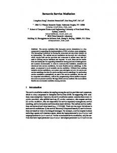
We show later the performance enhancement brought by our system in a different application where processing is exhaustive and memory reads and writes are not frequent. 450000 400000 350000 300000 250000 200000 150000 100000 50000 0
4500 4000 3500 3000 2500 2000 1500 1000 500 0
Figure 6. Hardware accelerator used in k-means PERFORMANCE EVALUATION
In order to obtain a view of the performance of the RASSD platform, we present in this section two testing scenarios, where each scenario is designed based on one of the two use-cases that we presented in the previous section. A. Virus Spread Testing We implemented the Virus Spread application consisting of executing four drivelets sequentially. The application was tested on a prototype RASSD platform that contains a Middleware Server connected to two ML605 boards acting as two RASSD nodes processing jobs in parallel. We measured 5 different delays in the total path from the client to the RASSD node and vice versa. These 5 delays can be described as follows: 1. Tapp-clm = time for request to be sent from the client to the Client Middleware Server (CLM) 2. TclmProc = time for the CLM to contact the database to decide which MWSs it needs to contact 3. TmwsProc = time for the MWS to prepare the command that will be sent to the RASSD, plus the time to contact the database to decide which RASSDs it needs to contact, plus aggregation time of intermediate results 4. Tmws-rassd = total communication time between the MWS and the RASSD node 5. TrassdProc = total processing time on the RASSD node. We performed three runs of the application on sample input files, varying in each run the population of individuals considered. The results in Figures 7-a (population of 10,000 individuals), 7-b (population of 1 million individuals) and 7c (population of 5 million individuals) show that the measured delays are all negligible, as compared to the processing delay on the RASSD nodes themselves, which comprise the processing delay of the four drivelets needed for the Virus Spread application. Through this test, we are modeling the worst case scenario, since this application does not incorporate exhaustive processing, and the time overhead in it results mostly from the memory reads and writes on the nodes. Figure 7-d shows how the processing time for this application increases linearly with increasing population, which proves that our system performs correctly and does not add any overhead to the applications even in the worst cases (applications that do not require a lot of processing).
(a)
(b)
2500000
2500
2000000
2000
1500000
1500
Time (s)
VI.
1000000 500000
1000 500
0 0 0
2000
4000
6000
Population (1000 records)
(c)
(d)
(e) Figure 7. Results of the Virus Spread application As mentioned earlier, the importance and prevalence of mobile applications nowadays encouraged us to account for them in our system, so we developed an interface that could allow a mobile application to communicate with our middleware and run over our system. To illustrate this mobile CLM, we tested the Virus Spreading application on an Android phone with Android 4.1.1 system and a 2 GB of RAM. While the results in Figure 7-e show an additional overhead with the mobile CLM, this overhead is still relatively small when the processing time on large data on the RASSD nodes is taken into consideration. B. k-means Testing To test the k-means application, we ran three different scenarios: The first scenario is running the algorithm on an Intel i7 processor with 8GB RAM running at 3.4 GHz. The second scenario runs the k-means drivelet on the ML605 board on which a MicroBlaze processor running at 150 MHz is installed. The third scenario runs the k-means as a hardware accelerator (as described earlier) that is running at 200 MHz. We tested three datasets of sizes: 10, 20, and 40 million points in a 2D space. The number of centroids (k)
was varied between 2 and 32. Figure 8-a shows the total delay of the third scenario for the 3 data sets. We notice that the delay increases as the size of the data set increases, which is logical. The significance of the results in Figure 7-a is demonstrated in Figure 8-b, which compares the third scenario with the 2 other scenarios. We notice that at k=32, hardware acceleration is 151 times faster than the Intel i7 processor and 350 × 103 times faster than the MicroBlaze (on FPGA) processor. Finally, Figure 8-c shows the energy saving that is gained by the hardware accelerator as compared to the software implementation (on MicroBlaze). The energy saving gain is defined as: Energy Saving =
(Total energy consumed by running k-means on the MicroBlaze) (Total energy consumed by running k-means as a hardware accelerator)
Figure 8-c shows that using a hardware accelerator reduces the energy consumed by the FPGA by a factor of 8376 when k=32, which is definitely a huge energy saving illustrating the efficiency of using hardware acceleration.
processing speed and storage of data. It also automates the management of operations needed to be executed by the processing nodes to attain the end goal of a data-intensive application. We presented two use-cases and tested their results using actual implemented prototypes. VIII.
This work has been supported by a generous grant from the Qatar National Research Fund (QNRF) under Grant Number NPRP 09-1050-2-405. REFERENCES [1]
[2]
[3]
[4]
[5]
[6]
(a)
(b) [7]
[8]
[9]
[10]
(c) Figure 8. Results for the k-means clustering application VII.
CONCLUSION
In this paper, we presented a design and architecture for the distributed middleware underlying the RASSD system we previously introduced. This middleware system allows for involving primitive hardware components, namely reconfigurable hardware, in a distributed environment, and using them to achieve better performance in terms of
ACKNOWLEDGMENT
[11]
[12]
N. Abbani, A. Ali, D. Al Otoom, M. Jomaa, M. Sharafeddine, H. Artail, H. Akkary, M. A. R. Saghir*, M. Awad, H. Hajj, “A Distributed Reconfigurable Active SSD Platform for Data Intensive Applications,” IEEE 13th International Conference on High Performance Computing and Communications (HPCC), Sept. 2011. F. Eliassen, A. Andersen, G. Blair, F. Costa, G. Coulson, V. Goebel, O. Hansen, T. Kristensen, T. Plagemann, H. Rafaelsen, K. Saikoski, and W. Yu, “Next Generation Middleware: Requirements, Architecture, and Prototypes”. K. Khedo, “Requirements for Next Generation Middleware Implementations”, In Proc. International Conf. on Computing in the Global Information Technology (ICCGI’06), 2006. J. Balasubramanian, A. Gokhale, D. Schmidt, and N. Wang, “Towards Middleware for Fault-Tolerance in Distributed Real-Time and Embedded Systems”, LNCS, v. 5053, pp. 72-85, 2008. S. Mahadevan, V.S. Gopinath, R. Lysecky, J. Sprinkle, J. Rozenblit, M.W. Marcellin, "Hardware/Software Communication Middleware for Data Adaptable Embedded Systems," Engineering of Computer Based Systems (ECBS), 2011 18th IEEE International Conference and Workshops on , vol., no., pp.34-43, 27-29 April 2011 Y. E. Krasteva, J. Portilla, E. de la Torre, T. Riesgo, "Embedded Runtime Reconfigurable Nodes for Wireless Sensor Networks Applications," Sensors Journal, IEEE , vol.11, no.9, pp.1800-1810, Sept. 2011. K. Henricksen, J. Indulska, T. McFadden, and S. Balasubramanian, “Middleware for Distributed Context-Aware Systems”, LNCS, v. 3760, pp. 846-863, 2005. S. Gorappa, “Performance Prediction of Component- and Patternbased Middleware for Distributed Systems”, In Proc. MDS’07, pp.16, 2007. A. Ali, M. Jomaa, B. Romanous, M. Sharafeddine, M. A. R. Saghir*, H. Akkary, H. Artail, M. Awad, H. Hajj, “An Operating System for a Reconfigurable Active SSD Processing Node,” 19th International Conference on Telecommunications (ICT), April 2012. M. Rodriguez-Martinez, N. Roussopoulos, “MOCHA: A SelfExtensible Database Middleware System for Distributed Data Sources,” Proceedings of the 2000 ACM SIGMOD international conference on Management of data SIGMOD ’00, Vol. 29, pp. 213224, June 2000. C. Barrett, K. Bisset, S. Eubank, X. Feng, and M. Marathe, “EpiSimdemics: an Efficient Algorithm for Simulating the Spread of Infectious Disease over Large Realistic Social Networks”, Proceedings of the ACM/IEEE Conference on High Performance Computing, Networking, Storage and Analysis (SC 2008), November 2008, Austin, Texas, USA. A. Jain, M. Murty, and P. Flynn, “Data Clustering: A Review”, ACM Computing Surveys, Vol. 31, No. 3, September 1999, pp. 264-323